Advertisement
- 1 Overview
- 2 Hardware and Installation
- 3 Reset
- 4 Levels and Metering
- 5 Mute Sync
- 6 Signal Flow and Connections
- 7 Summing
- 8 Parametric Equalizer
- 9 Software Installation, Management, and Security
- 10 Firmware Updates
- 11 Encryption
- 12 Using Command Strings
- 13 Networking and Dante
- 14 Specifications
- 15 Accessories
- 16 Documents / Resources
Overview
General Description
The Shure ANI4IN Audio Network Interface converts 4 analog audio channels into independent digital audio channels on a Dante™network. Microphone, auxiliary, and line-level devices are supported, with adjustable gain and +48V phantom power for each channel. In networked conferencing systems, the Audio Network Interface provides a simple way to connect analog equipment onto the audio network, such as wireless microphones. The web application controls signal routing and channel settings from any computer connected to the same network.
Model Variations
ANI4IN-XLR: Four XLR inputs (balanced audio only)
ANI4IN-BLOCK: Four 6-pin block connector inputs (balanced audio and logic connections)
Hardware and Installation
Hardware
Block Connector Model:

XLR Model:

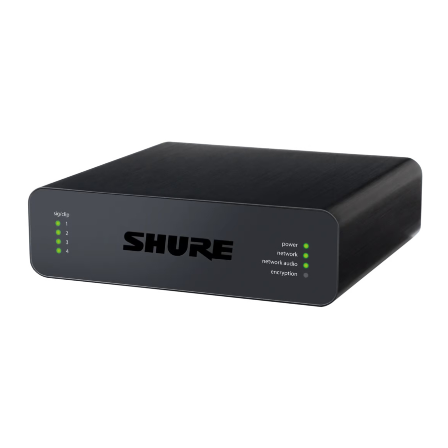
- Input Signal Clip Indicators
Each indicator corresponds to a single input channel. If the LED turns red, attenuate the level from the source device to prevent clipping at the input stage. Analog and digital gain adjustments are made through the web application.LED State Audio Signal Level Off less than -60 dBFS Green -59 dBFS to -24 dBFS Yellow -23 dBFS to -1 dBFS Red 0 dBFS or more - Audio and Logic Inputs
Note: Logic connections are only featured on the block connector version
Block Inputs: Each input receives balanced audio and logic signals. Pin assignments are as follows:+ Audio + - Audio - ![]()
Audio ground switch Logic Mute (sent from microphone) led Logic LED (received by microphone) gnd Logic ground XLR Inputs: Each input receives a balanced audio signal. Pin assignments are as follows:
1 Ground 2 Positive 3 Negative - Chassis Ground Screw
Provides an optional connection for microphone shield wire to chassis ground
Note: only applies to block connector version - LED Indicators
Power: Power over Ethernet (PoE) present
Note: Use a PoE injector if your network switch does not supply PoE.
Network: Network connection active
Network Audio: Dante audio present on the network
Note: Error details are available in the event log in the web application.
Encryption: Not currently supportedLED Status Activity Off No active signal Green Device is operating successfully Red Error has occurred. See event log for details. - Dante Network Port
Connects to a network switch to send Dante audio, while receiving Power over Ethernet (PoE) and data from the control software. See the Dante and networking section for additional information. - Reset Button
Resets the device settings back to the factory default.

Power Over Ethernet (PoE)
This device requires PoE to operate. It is compatible with both Class 0 and Class 3 PoE sources.
Power over Ethernet is delivered in one of the following ways:
- A network switch that provides PoE
- A PoE injector device
Installation and Rack Mounting
Two mounting solutions are available for installing the Audio Network Interface:
CRT1 19" Rack Tray (optional accessory): Supports up to 3 devices; mountable in a rack or under a table
Single-unit Mounting Tray (included accessory): Supports a single device for mounting under a table
Securing the Devices
Use the included screws from the mounting hardware kit to secure the Audio Network Interfaces. Audio Network Interfaces can be mounted to face either direction. Insert the screws from the bottom in the appropriate holes, according to the following diagrams:

Align the holes as shown for securing a single device in the single-unit mounting tray

Align the holes as shown for securing up to 3 devices in the 19" rack tray.
Rack Ear Configuration
A combination of up to 3 Audio Network Interfaces can be mounted in a single 19-inch rack space. The adjustable rack ears support mounting in a standard equipment rack or underneath a table.
Standard 19" Rack Mount

- Align the ears with the mounting holes pointed forward.
- Install the 3 screws that hold the ear to the tray as shown.
Under-Table Mounting

- Align the ears with the mounting holes pointed upward.
- Install the 3 screws that hold the ear to the tray as shown.
Installing Underneath a Table
- Hold the tray in the desired location under a table.
- Use a pencil to mark the location of the mounting holes on the table.
- Drill 4 holes for the screws. The diameter of the holes in the tray are 7.1 mm.
- Install the components into the tray.
- Install with 4 screws to secure the tray underneath the table.
Reset
The reset button is located inside a small hole in the rear panel. Use a paperclip or other small tool to press the button.
There are two hardware reset functions:
Network reset (press button for 4-8 seconds)
Resets all Shure control and audio network IP settings to factory defaults
Full factory reset (press button for longer than 8 seconds)
Restores all network and Designer settings to the factory defaults.
Software Reset Options
To simply revert settings without a complete hardware reset, use one of the following options:
Reboot Device: Power-cycles the device as if it were unplugged from the network. All settings are retained when the device is rebooted.
Default Settings: To revert audio settings back to the factory configuration (excluding Device Name, IP Settings, and Passwords), select Load Preset and choose the default settings preset.
Levels and Metering
Adjusting Input Levels
Before you begin, verify that levels from the analog devices with adjustable output levels are operating at nominal levels.
The analog gain adjusts the level of the audio signal before it is converted from analog to digital. It is adjustable in 3 dB increments, with up to 51 dB total gain.
- Set the Metering to Pre-fader in the toolbar at the top of the workspace to monitor analog signal levels
- Select the analog gain value to open the fader
- Match the analog gain setting to the incoming signal level. Use the gain range markers on the fader to apply the appropriate amount of gain:
Source Level Gain Range Line (+4 dBu) 0 to +9 dB Auxiliary (-10 dBV) +9 to +21 dB Microphone (varies) +21 to +51 dB - The meters should peak between -18 and -9 dB.
Note: Leaving some additional headroom is a recommended to prevent clipping if mobile devices will be plugged into particular channels.
Adjusting Output Levels
Output levels are controlled by the Digital Gain (dB) fader. Always adjust the input gain (analog) before the output gain (digital). In most cases, setting the analog gain correctly results in an appropriate output level. Sources that have a quiet signal, such as a microphone with low sensitivity, may need someDigital Gain (dB) applied. If adjustments to the Digital Gain (dB) fader are required, follow these steps:
- Set the Metering to Post-fader in the toolbar at the top of the workspace.
- Adjust theDigital Gain (dB) fader as needed.
- If using summing, use the Digital Gain (dB) faders to mix the channel levels.
Metering Options (Pre-fader and Post-fader)
There are two modes for monitoring, for input and output signals to be monitored separately.
")
Pre-Fader (Analog Input Level)
Pre-fader metering displays the signal level before it reaches the digital gain fader, so that input signal levels can be optimized for each channel. Analog gain adjustments affect the meter when set to pre-fader, but the digital gain adjustments do not.

If the incoming signal is adjustable (wireless microphone systems, for example), make sure it is at the nominal level before adjusting the analog gain on the Audio Network Interface.
Post-Fader (Digital Output Level)
Post-fader metering displays the signal level at the very end of the signal chain, which includes both the analog and digital gain. Use this setting to meter the levels that are being sent over the Dante network.
Mute Sync
Mute sync ensures that all connected devices in a conferencing system mute or unmute at the same time and at the correct point in the signal path. Mute status is synchronized in the devices using logic signals or USB connections.
To use mute sync, make sure logic is enabled on all devices.
Designer's Optimize workflow configures all necessary mute sync settings for you.
Compatible Shure logic devices:
- P300 (Also mutes supported soft codecs connected by USB)
- ANIUSB-MATRIX (Also mutes supported soft codecs connected by USB)
- IntelliMix® Room software (Also mutes supported soft codecs connected by USB)
- MXA910
- MXA710
- MXA310
- Network Mute Button
- ANI22-BLOCK
- ANI4IN-BLOCK
- Logic-enabled MX microphones connected to ANI22-BLOCK or ANI4IN-BLOCK
- MX392
- MX395-LED
- MX396
- MX405/410/415
To use mute sync, connect a logic-enabled MX series microphone to an ANI4IN-BLOCK or ANI22-BLOCK.
Note: See microphone guides to learn how to turn on logic on mics.
For help with specific mute sync implementations, see our FAQs.
Signal Flow and Connections
Setting up the Audio Network
Shure networked conferencing systems are comprised of Microflex Advance microphones and network interfaces, which operate entirely on a Dante network. Additional hardware, including network switches, computers, loudspeakers, and audio processors are described in the hardware component index.
Shure components shown in this diagram:
Microflex Advance Microphones
The MXA910 and MXA310 are equipped with Dante outputs, and connect directly to a network switch.
Audio Network Interfaces
The interfaces are used to connect analog devices such as loudspeakers and analog microphones to the network.

ANI4IN: Converts 4 analog signals (separate XLR and block connector models available) into Dante digital audio signals.
ANI4OUT: Converts 4 channels of Dante audio from the network into analog signals.
This diagram shows the entire signal path through a networked conference system. Signals from the near end and far end are exchanged through an audio processor connected to a phone system, or through a computer connected to the internet. Analog microphones connect to the network through the Shure ANI4IN, while loudspeakers connect through the Shure ANI4OUT.

This diagram shows Microflex Advance components in context, with two rooms communicating through video codecs.
Controlling Hardware and Audio Over the Network
Audio and hardware settings are managed through a computer connected to the same network.
Shure Hardware and Audio
Each Microflex Advance component has a web application which provides mixing and configuration tools to optimize sound quality.
Expanded Control for Analog Devices
Analog devices that are connected to the network through a Shure network interface (ANI4IN/ANI4OUT) benefit from additional remote control: Volume levels, equalization, and signal routing are managed through the web application. For example, adjusting loudspeaker volume or muting a wired microphone, which would normally be done from the hardware, can now be controlled remotely over the network.
Dante Signal Routing
You can manage signal routing with Dante Controller or Shure Designer software.
Connections and Signal Flow

- MX396 (Dual-element)
In addition to running the audio signals, this boundary microphone features three additional wire leads for logic connections. This allows the switch on the microphone to send a logic mute signal to other equipment on the network, and to receive a logic LED control signal. - MX392
In addition to running the audio signal, this boundary microphone features three additional wire leads for logic connections. This allows the switch on the microphone to send a logic mute signal to other equipment on the network, and to receive a logic LED control signal. - ULX-D Receiver
Wireless microphones connect to the network interface through the balanced analog outputs on the receiver. - Network Switch
Provides connectivity between the Dante audio network and the computer that controls signal processing and routing. - Computer
A computer or tablet running the web application provides independent gain control for each connected device.
Input: Analog (4 XLR or Block Connectors)
Each Audio Network Interface has 4 analog inputs with variable analog gain for line, auxiliary, and microphone-level signals. Examples of devices to connect to the network with the Audio Network Interface:
- Wireless microphone systems
- Wired installed microphones (logic functions supported by block connector model)
- Computers or mobile devices used for presentations
- Other playback devices
Output: Dante Digital Audio
Connect the Dante output to a network switch with a network cable. A single network cable delivers all 4 channels of audio onto the network, and carries Power over Ethernet (PoE) to power the device. Use Dante Controller to route audio channels from the Audio Network Interface to the appropriate network destination. Any of the signals may be routed to multiple destinations, to provide local reinforcement while simultaneously delivering audio to the far end.
Summing
The Audio Network Interface provides channel summing to combine input signals and send them over a single Dante channel. This makes it possible to send all channels to a device with a limited amount of Dante receiver channels. Mixer functionality does not change; audio channels are simply sent as one combined signal.
Note: When summing is enabled, a limiter is activated to prevent signal overloading. The limiter never applies to the direct outputs, and only affects the summed signal.
To enable, select one of the summing options in the toolbar at the top of the mixer in the channels tab.

Example Scenario
A common application that requires summing is a video conference where there are multiple microphones. When a device (a computer running conferencing software and Dante Virtual Soundcard, for example) only supports 1 or 2 Dante receiver channels, the Audio Network Interface combines the input signals to transmit as a single Dante channel.

- Summed analog audio channels
When the 4 analog audio channels are summed, each of the Dante transmit channels includes all of the input signals. - Single Dante audio channel
One Dante signal is sent over the network, which contains all 4 summed channels. - Connection to computer
A computer that is running limited number of Dante channels with Dante Virtual Soundcard, receives all audio on a single channel. This audio is sent to the far end.
Parametric Equalizer
Maximize audio quality by adjusting the frequency response with the parametric equalizer.
Common equalizer applications:
- Improve speech clarity
- Reduce noise from HVAC systems or video projectors
- Reduce room irregularities
- Adjust frequency response for reinforcement systems
Setting Filter Parameters
Adjust filter settings by manipulating the icons in the frequency response graph, or by entering numeric values. Disable a filter using the check-box next to the filter.
| Filter Type | Only the first and last band have selectable filter types. Parametric: Attenuates or boosts the signal within a customizable frequency range Low Cut: Rolls off the audio signal below the selected frequency Low Shelf: Attenuates or boosts the audio signal below the selected frequency High Cut: Rolls off the audio signal above the selected frequency High Shelf: Attenuates or boosts the audio signal above the selected frequency |
| Frequency | Select the center frequency of the filter to cut/boost |
| Gain | Adjusts the level for a specific filter (+/- 30 dB) |
| Q Width | Adjusts the range of frequencies affected by the filter. As this value increases, the bandwidth becomes thinner. |

Equalizer Applications
Conferencing room acoustics vary based on room size, shape, and construction materials. Use the guidelines in following table.
| EQ Application | Suggested Settings |
| Treble boost for improved speech intelligibility | Add a high shelf filter to boost frequencies greater than 1 kHz by 3-6 dB |
| HVAC noise reduction | Add a low cut filter to attenuate frequencies below 200 Hz |
| Reduce flutter echoes and sibilance | Identify the specific frequency range that "excites" the room:
|
| Reduce hollow, resonant room sound | Identify the specific frequency range that "excites" the room:
|
Software Installation, Management, and Security
Software Installation and Device Discovery
The Shure Web Device Discovery application is used to access the web application for a Shure device. The web application opens in a web browser to provide comprehensive device management. Any computer networked to the device can access the GUI with this application.
Compatible Browsers:
- Chrome
- Safari
- Firefox
- Internet Explorer
- Install the Shure device discovery application, available at www.shure.com
- Double-click the component to open the interface.
Accessing the Web Application
The Shure Web Server Discovery application finds all Shure devices on the network that feature a web-based GUI. Follow these steps to install the software and access the web application:
- Install the Shure Discovery application
Download and install the Shure Discovery application from www.shure.com. This automatically installs the required Bonjour device discovery tool on the computer. - Connect the network
Ensure the computer and the hardware are on the same network. - Launch the Discovery application
The app displays all Shure devices that feature a GUI. - Identify the hardware
Double-click on a device to open its GUI in a web browser. - Bookmark the device's web application (recommended)
Bookmark the device's DNS name to access the GUI without the Shure Discovery app.
Accessing the Web Application without the Discovery App
If the Discovery application is not installed, the web application can be accessed by typing the DNS name into an internet browser. The DNS name is derived from model of the unit, in combination with the last three bytes (six digits) of the MAC address, and ending in.local.
Format Example: If the MAC address of a unit is 00:0E:DD:AA:BB:CC, then the link is written as follows:
ANI4IN: http://ANI4IN-aabbcc.local
ANI4OUT: http://ANI4OUT-aabbcc.local
Channel Utilities
+48V (Phantom Power)
Delivers + 48V phantom power to the selected channel
Polarity Reverse
Each channel has a checkbox to reverse the polarity of the input signal.
Analog Gain
Adjusts the gain to optimize input signal level before the analog audio is converted to a digital audio.
Digital Gain
Adjusts the digital signal level to optimize the signal strength over the network.
Mute Groups
Check the Mute group box to add the channel to a group. Muting any channel within the Mute group mutes all channels in the group.
Fader Groups
Check the Fader group box to add the channel to a group. All faders within the group are linked, and move together when a single fader is adjusted.
Logic Switch Indicator
Illuminates when a switch logic signal is received by the Audio Network Interface from a microphone.
Note: only applies to block connector model.
Logic LED Indicator
Illuminates when an LED logic signal is received by the Audio Network Interface through the network from a control system.
Note: only applies to block connector model.
Custom Presets
Use presets to quickly save and recall settings. Up to 10 presets can be stored on each device to match various seating arrangements. A preset saves all device settings except for the Device Name, IP Settings, and Passwords. Importing and exporting presets into new installations saves time and improves workflow. When a preset is selected, the name displays above the preset menu. If changes are made, an asterisk appears next to the name.
Note: Use the default settings preset to revert to the factory configuration (excludes Device Name, IP Settings, and Passwords).
| save as preset: | Saves settings to the device |
| load preset: | Opens a configuration from the device |
| import from file: | Downloads a preset file from a computer onto the device. Files may be selected through the browser or dragged into the import window. |
| export to file: | Saves a preset file from the device onto a computer |
Event Log
The event log provides a detailed account of activity from the moment the device is powered on. The log collects up to 1,000 activity entries and time-stamps them relative to the last power cycle. The entries are stored in the internal memory, and are not cleared when the device is power-cycled. The Export feature creates a CSV (comma separated values) document to save and sort the log data.
Refer to the log file for details when troubleshooting or consulting with Shure Systems Support.
To view the event log:
- Open the Help menu
- Select View Event Log
Severity Level
Information
An action or event has been successfully completed

An action cannot be complete, but overall functionality is stable
Error
A problem has occurred that could inhibit functionality.
Log Details
Description
Provides details on events and errors, including IP address and subnet mask.
Time Stamp
Power cycles: days: hours: minutes: seconds since most recent boot-up.
Event ID
Indicates event type for internal reference.
Tip: Use the filter to narrow down results. Select a category heading to sort the log.
Firmware Updates
Firmware is embedded software in each component that controls functionality. Periodically, new versions of firmware are developed to incorporate additional features and enhancements. To take advantage of design improvements, new versions of the firmware can be uploaded and installed using the Shure Update Utility. Software is available for download from http:// www.shure.com.
When components are connected through the Shure MXW Audio Network Interface, their firmware must be updated on one device at a time prior to updating the MXW Audio Network Interface firmware. Attempting to update all devices at once will cause the interface to reboot after its firmware is updated, and the connection to other networked components will be lost.
Perform the following steps to update the firmware:

Ensure the device has a stable network connection during the update. Do not turn off the device until the update is complete.
- Connect the device and computer to the same network (set to the same subnet).
- Download Shure Update Utility app and install it.
- Open the application.
- Click Check For Updates... button to view new firmware versions available for download.
- Select the desired firmware and press Downloadto download it to the Firmware Library.
- From the Update Devices tab, select the new firmware and press Send Updates... to begin the firmware update, which overwrites the existing firmware on the device.
Note: After updating, you may need to clear your browser's cache to display updates to the device's web application.
Firmware Release Requirements
All devices comprise a network with multiple communications protocols that work together to ensure proper operation. The recommended best practice is that all devices are on an identical release. To view the firmware version of each device on the network, open the component user interface, and look under Settings > About.
The format for Shure device's firmware is MAJOR.MINOR.PATCH. (Ex. 1.6.2 where 1 is the Major firmware level, 6 is the Minor firmware level, and 2 is the Patch firmware level.) At minimum, devices that operate on the same subnet should have identical MAJOR and MINOR release numbers.
- Devices of different MAJOR releases are not compatible.
- Differences in the PATCH firmware release level may introduce undesired inconsistencies.
Encryption
Audio is encrypted with the Advanced Encryption Standard (AES-256), as specified by the US Government National Institute of Standards and Technology (NIST) publication FIPS-197. Shure devices that support encryption require a passphrase to make a connection. Encryption is not supported with third-party devices.
To activate encryption:
- Open the Settings menu and select the General tab.
- Select Enable Encryption.
- Enter a passphrase. All devices must use the same passphrase to establish an encrypted connection.
For encryption to work, all Shure devices on your network must use encryption.
![]() If you're using Shure Designer software to configure your system, please check the Designer help section for more about this topic.
If you're using Shure Designer software to configure your system, please check the Designer help section for more about this topic.
Using Command Strings
This device receives logic commands over the network. Many parameters controlled through Designer can be controlled using a third-party control system, using the appropriate command string.
Common applications:
- Mute
- LED color and behavior
- Loading presets
- Adjusting levels
A complete list of command strings is available at: pubs.shure.com/command-strings/ANI4IN.
Logic Applications
The block connecter model variation (ANI4IN-BLOCK) features three logic signal connections. Logic signals are converted into Ethernet command strings and sent and received by any device (such as an echo canceller or control system) that supports Ethernet command strings.
In this diagram, Shure MX392 and MX396 Microflex® microphones are connected the audio network interface. The mute button on each microphone sends a logic signal (switch) to mute other audio equipment. The microphones receive logic signals (LED) so that the microphone LED behavior reflects the state of the entire audio system.

Networking and Dante
Digital Audio Networking
Dante digital audio is carried over standard Ethernet and operates using standard internet protocols. Dante provides low latency, tight clock synchronization, and high Quality of Service (QoS) to provide reliable audio transport to a variety of Dante devices. Dante audio can coexist safely on the same network as IT and control data, or can be configured to use a dedicated network.
Switch and Cable Recommendations for Dante Networking
Switches and cables determine how well your audio network performs. Use high quality switches and cables to make your audio network more reliable.
Network switches should have:
- Gigabit ports. 10/100 switches may work on small networks, but gigabit switches perform better.
- Power over Ethernet (PoE) or PoE+ ports for any devices that require power
- Management features to provide information about port speed, error counters, and bandwidth used
- Ability to switch off Energy Efficient Ethernet (EEE). EEE (also known as "Green Ethernet") may cause audio dropouts and problems with clock synchronization.
- Diffserv (DSCP) Quality of Service (QoS) with strict priority and 4 queues
Ethernet cables should be:
- Cat5e or better
- Shielded
Dante Transmit Flows
This device supports up to two transmit flows and two receive flows. A single flow consists of up to four channels, through either a unicast or multicast transmission.
- A unicast flow is a point-to-point connection between two devices, supporting up to four channels per flow.
- A multicast flow is a one-to-many transmission, which supports sending up to four channels to multiple receiving devices across the network.
Shure Device Applications
This device can connect with up to two Dante devices.
The Shure MXA310, ANI22, ANIUSB-MATRIX and ANI4IN support multicast transmission. This means that flows can transmit to multiple devices -- as many as the network can support. If using unicast flows, each of these devices can connect with up to two Dante receiver devices.
The Shure ANI4OUT connects with up to two Dante transmitter devices.
Compatibility with Dante Domain Manager
This device is compatible with Dante Domain Manager software (DDM). DDM is network management software with user authentication, role-based security, and auditing features for Dante networks and Dante-enabled products.
Considerations for Shure devices controlled by DDM:
- When you add Shure devices to a Dante domain, set the local controller access to Read Write. Otherwise, you won't be able to access to Dante settings, perform a factory reset, or update device firmware.
- If the device and DDM can't communicate over the network for any reason, you won't be able to control Dante settings, perform a factory reset, or update device firmware. When the connection is reestablished, the device follows the policy set for it in the Dante domain.
- If Dante device lock is on, DDM is offline, or the configuration of the device is set to Prevent, some device settings are disabled. These include: Dante encryption, MXW association, AD4 Dante browse and Dante cue, and SCM820 linking.
See Dante Domain Manager's documentation for more information.
QoS (Quality of Service) Settings
QoS settings assign priorities to specific data packets on the network, ensuring reliable audio delivery on larger networks with heavy traffic. This feature is available on most managed network switches. Although not required, assigning QoS settings is recommended.
Note: Coordinate changes with the network administrator to avoid disrupting service.
To assign QoS values, open the switch interface and use the following table to assign Dante®-associated queue values.
- Assign the highest possible value (shown as 4 in this example) for time-critical PTP events
- Use descending priority values for each remaining packet.
Dante QoS Priority Values
| Priority | Usage Time-critical PTP | DSCP Label | Hex | Decimal | Binary |
| High (4) | Time-critical PTP events | CS7 | 0x38 | 56 | 111000 |
| Medium (3) | Audio, PTP | EF | 0x2E | 46 | 101110 |
| Low (2) | (reserved) | CS1 | 0x08 | 8 | 001000 |
| None (1) | Other traffic | BestEffort | 0x00 | 0 | 000000 |
Note: Switch management may vary by manufacturer and switch type. Consult the manufacturer's product guide for specific configuration details.
For more information on Dante requirements and networking, visit www.audinate.com.
Networking Terminology
PTP (Precision Time Protocol): Used to synchronize clocks on the network
DSCP (Differentiated Services Code Point): Standardized identification method for data used in layer 3 QoS prioritization
Packet Bridge
Packet bridge enables an external controller to obtain IP information from the control interface of a Shure device. To access the packet bridge, an external controller must send a query packet over unicast UDP* to port 2203 on the Dante interface of the Shure device.
- Send a UDP packet with a minimum 1-byte payload. Note: The maximum accepted payload 140 bytes. Any content is allowed.
- The Shure device will send a response packet over unicast UDP to the controller, using a destination UDP port identical to the source port of the query packet. The payload of the response packet follows this format:
Note: The Shure device should respond in less than one second on a typical network. If there is no response, try sending the query again after verifying the destination IP address and port number.Bytes Content 0-3 IP address, as 32-bit unsigned integer in network order 4-7 Subnet mask, as 32 bit unsigned integer in network or der 8-13 MAC address, as array of 6 bytes
*UDP: User Datagram Protocol
Specifications
Inputs
| ANI4IN-XLR | (4) XLR connector |
| ANI4IN-BLOCK | (4) 6-pin block connector |
Phantom Power
selectable per channel
+48 V
Logic Connections (Block connectors only)
Sent as Ethernet command strings
LED(+5 V), Switch
Polarity
Non-inverting, any input to any output
Output
(1) RJ45
Power Requirements
Power over Ethernet (PoE), Class 0
Power Consumption
10W, maximum
Weight
672 g (1.5 lbs)
Dimensions
H x W x D
4 x 14 x 12.8 cm ( 1.6 x 5.5 x 5.0 in.)
control application
HTML5 Browser-based
Operating Temperature Range
−6.7°C (20°F) to 40°C (104°F)
Storage Temperature Range
−29°C ( 20°F) to 74°C (165°F)
Audio
Frequency Response
20 to 20,000 Hz
Dante Digital Output
| Channel Count | 4 |
| Sampling Rate | 48 kHz |
| Bit Depth | 24 |
Latency
Does not include Dante latency
0.35 ms
analog gain range
Adjustable in 3 dB steps
51 dB
Dynamic Range (Analog-to-Dante)
20 Hz to 20 kHz, A-weighted, typical
113 dB
Equivalent Input Noise
20 Hz to 20 kHz, A weighted, input terminated with 150Ω
| Analog Gain Setting= +0 dB | 93 dBV |
| Analog Gain Setting= +27 dB | 119 dBV |
| Analog Gain Setting= +51 dB | 130 dBV |
Total Harmonic Distortion
@ 1 kHz, 0 dBV Input, 0 dB analog gain
<0.05%
Common Mode Rejection Ratio
150Ω balanced source @ 1 kHz
>70 dB
Impedance
5 kΩ
Input Configuration
Active Balanced
Input Clipping Level
| Analog Gain Setting= +0 dB | +20 dBV |
| Analog Gain Setting= +27 dB | 7 dBV |
| Analog Gain Setting= +51 dB | 31 dBV |
Built-in Digital Signal Processing
Per Channel Equalizer (4 band Parametric), Mute, , Gain ( 140 dB range)
System Audio Summing
Networking
Cable Requirements
Cat 5e or higher (shielded cable recommended)
IP Ports and Protocols
Shure Control
| Port | TCP/UDP | Protocol | Description | Factory De fault |
| 21 | TCP | FTP | Required for firmware updates (otherwise closed) | Closed |
| 22 | TCP | SSH | Secure Shell Interface | Closed |
| 23 | TCP | Telnet | Not supported | Closed |
| 53 | UDP | DNS | Domain Name System | Closed |
| 67 | UDP | DHCP | Dynamic Host Configuration Protocol | Open |
| 68 | UDP | DHCP | Dynamic Host Configuration Protocol | Open |
| 80* | TCP | HTTP | Required to launch embedded web server | Open |
| 443 | TCP | HTTPS | Not supported | Closed |
| 2202 | TCP | ASCII | Required for 3rd party control strings | Open |
| 5353 | UDP | mDNS † | Required for device discovery | Open |
| 5568 | UDP | SDT (multicast) † | Required for inter-device communication | Open |
| 57383 | UDP | SDT (unicast) | Required for inter-device communication | Open |
| 8023 | TCP | Telnet | Debug console interface | Closed |
| 8180 | TCP | HTML | Required for web application (legacy firmware only) | Open |
| 8427 | UDP | SLP (multicast)† | Required for inter-device communication | Open |
| 64000 | TCP | Telnet | Required for Shure firmware update | Open |
*These ports must be open on the PC or control system to access the device through a firewall.
†These protocols require multicast. Ensure multicast has been correctly configured for your network.
See Audinate's website for information about ports and protocols used by Dante audio.
Accessories
Furnished Accessories
| Hardware kit (XLR model) | 90A29254 |
| Hardware kit (block connector model) | 90B29252 |
| Mounting Bracket (1/3 rack unit) | 53A27742 |
Optional Accessories and Replacement Parts
19" rack tray CRT1

Documents / Resources
References
![www.shure.com]() IntelliMix P300 - Audio Conferencing Processor - Shure USA
IntelliMix P300 - Audio Conferencing Processor - Shure USA![www.shure.com]() ANIUSB-MATRIX - ANIUSB-MATRIX USB Audio Network Interface with Matrix Mixing - Shure USA
ANIUSB-MATRIX - ANIUSB-MATRIX USB Audio Network Interface with Matrix Mixing - Shure USA![www.shure.com]() IntelliMix® Room - Audio Processing Software - Shure USA
IntelliMix® Room - Audio Processing Software - Shure USAService
Shure: Microphones, Wireless microphones, in-ear monitoring, earphones, headphones
ANI4IN Command Strings
![audinate.com]() Audinate - Maker of Dante, Pro AV's Leading Networking Technology
Audinate - Maker of Dante, Pro AV's Leading Networking Technology![www.audinate.com]() Audinate - Maker of Dante, Pro AV's Leading Networking Technology
Audinate - Maker of Dante, Pro AV's Leading Networking Technology![www.audinate.com]() Which network ports does Dante use? | Audinate | FAQs
Which network ports does Dante use? | Audinate | FAQs
Download manual
Here you can download full pdf version of manual, it may contain additional safety instructions, warranty information, FCC rules, etc.
Advertisement
Thank you! Your question has been received!


Need Assistance?
Do you have a question about the ANI4IN that isn't answered in the manual? Leave your question here.