
Related Manuals for Sinclair SDV 6 SWC-61


Summary of Contents for Sinclair SDV 6 SWC-61
- Page 1 USER & INSTALLATION MANUAL SWC-61 C O M M E R C I A L A I R C O N D I T I O N E R S S D V 6...
-
Page 2: Table Of Contents
This manual gives detailed description of the precautions that should be brought to your attention during operation. In order to ensure correct service of the wired controller please read this manual carefully before using the unit. For convenience of future reference, keep this manual after reading it. - Page 3 5 OPERATION INSTRUCTIONS Control Panel Explanation Display Explanation Operation Instructions Mode Conflict Prompt Project Commissioning...
-
Page 4: General Safety Precautions
1 GENERAL SAFETY PRECAUTIONS 1.1 About the documentation The original documentation is written in English. All other languages are translations. The precautions described in this document cover very important topics, follow them carefully. All activities described in the installation manual must be performed by an authorized installer. -
Page 5: For The User
WARNING Indicates a situation that could result in death or serious injury. CAUTION Indicates a situation that could result in minor or moderate injury. NOTE Indicates a situation that could result in equipment or property damage. INFORMATION Indicates useful tips or additional information. 1.2 For the user If you are not sure how to operate the unit, contact your installer. - Page 6 The appliance is not intended for use by persons, including children, with reduced physical, sensory or mental capabilities, or lack of experience and knowledge, unless they have been given supervision or instruction concerning use of the appliance by a person responsible for their safety. Children must be supervised to ensure that they do not play with the product.
- Page 7 Units are marked with the following symbol: This means that electrical and electronic products may not be mixed with unsorted household waste. Do not try to dismantle the system yourself: the dismantling of the system, treatment of the refrigerant, of oil and of other parts must be done by an authorized installer and must comply with applicable legislation.
-
Page 8: Basic Parameters
2 BASIC PARAMETERS Items Description Rated voltage DC18V Wiring size RVVP-0.75mm ×2 Operating environment -5°C ~ 43°C Humidity ≤ RH90% 3 ACCESSORIES LIST Name Quantity Wired controller Philips head screw, M4×25 Installation and Operation Manual Plastic support bar Bottom cap of the wired controller Round head screw ST4X20 Plastic expansion pipe... -
Page 9: Installation
4 INSTALLATION 4.1 Installation Precautions ● To ensure correct installation, read the "Installation" section of this manual. ● The content provided here covers warnings, which contain important information about safety that must be followed. CAUTION Entrust a local distributor or local service agent to appoint a qualified technician to perform the installation. - Page 10 ine or be laid in the same wiring tube together with the high voltage line. The minimum spacing of wiring tubes is 300 to 500 mm. Do not install the wired controller in corrosive, flammable and explosive environments or places with oil mist (such as a kitchen).
-
Page 11: Installation Method
4.2 Installation Method 4.2.1 Wiring requirements One-to-more and two-to-more IDU 2# IDU 16# IDU 1# D1 D2 D1 D2 D1 D2 X1 X2 ··· IDU 3-15# Please use the shielded wire, and the shield layer must be grounded. Please use shielded wires, and the shield layer cannot be grounded. - Page 12 One-to-one ● Applicable to bi-directional communication between wired controller and IDU. ● One-to-one: One wired controller controls one IDU. The parameters displayed on the wired controller are updated in real time according to changes in the parameters of the IDU. ●...
- Page 13 Two-to-one Applicable to bi-directional communication between wired controller and IDU. Two-to-one: Two wired controller controls one IDU. The parameters displayed on the wired controller are updated in real time according to changes in the parameters of the IDU. Two-to-one:wired controller must be set as main or secondary.
- Page 14 4.2.2 Installlation of bottom cap of the wired controller Screw hole installed on Screw hole the wall Use installed on 86 three round Electrician box, head screw use two Philips ST4X20 and head screw, plastic M4×25 expansion pipe When installed on 86 Electrician box: Adjust the lengths of the two plastic support bars in the accessory package.
- Page 15 When installed on the wall: The wire can be placed outlet or inside. Wire outlet have four side to select. Cutting place of up,down,left and right side wire outlet Up ,down,left and right side wire outlet 4.2.3 Lead the 2-core shielded cable through the wiring hole in the bottom cap of the wired controller, and use screws to reliably fasten the shielded cable onto terminals X1 and X2.
- Page 16 NOTE Do not perform wiring operations on energized parts. Make sure that you remove the wired controller before proceeding. Otherwise, the wired controller may be damaged. Do not overtighten the pan head screws; otherwise, the bottom cap of the wired controller may deform and cannot be levelled on the wall surface, which makes it difficult to install or not securely installed.
- Page 17 Avoid the water enter into the wired remote controller, use trap and putty to seal the connectors of wires during wiring installation. 86Electrician box wire inside wire outlet 4.2.4 Buckle the wired controller and the rear cover as shown in the following figure.
- Page 18 When they are correctly buckled NOTE Make sure that no cables are clamped when buckling the wired controller and bottom cap. The wired controller and bottom cap should be installed correctly. Otherwise, they may get loose and fall apart.
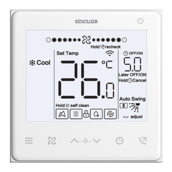
- Page 19 5 OPERATION INSTRUCTIONS 5.1 Control Panel Explanation Fan speed/sleep On/Off Operating indicator Auto No permission Hold recheck AU-heat Auto Set Temp Humidity OFF/ON Cool Timer Later OFF/ON Operating Hold Cancel mode Sterilize Heat Comfor air Self Auto Swing Clean Hold self clean SYS.
- Page 20 5.2 Display Explanation NO. Icon Name Description It will be flashed when IDU energy efficiency attenuated.When "Parameter settings C17" is seted "yes",the screen displays IDU Energy Energy Efficiency Attenuation Attenuation percentage and filter blockage percentage will be displayed alternately in off mode when "Parameter settings C17 and C18"...
- Page 21 5.3 Operation Instructions On/Off Press " " to turn on or off the IDU. INFORMATION The screen and operating indicator get dimmed when the unit is powered off. The icon is displayed when the IDU is off. Each time " "...
- Page 22 5.3.1 Self clean function self clean Press and hold " " for 2s to start self clean function. function. The self-cleaning process takes approximately 50 minutes and falls into four steps: Melting and Preprocessing Freezing Drying cleaning Auto No permission Hold recheck AU-heat...
- Page 23 INFORMATION To exit self clean function during operation, press " ". Some models do not have self clean function. For details, please refer to the manual of IDU. When self clean function is enabled, all indoor units (sharing the same outdoor unit) start the process of self clean function.
- Page 24 INFORMATION After sleep mode has been running for 8 hours, the " " icon is dimmed and the unit will exit the mode automatically. Press the fan speed button to exit sleep mode. In Auto mode and Dry mode, fan speed is automatic by default, and the fan speed is unadjustable.
- Page 25 Auto Swing Comfor air Position 2 Position 3 Position 4 Position 5 Position 1 INFORMATION It applies to IDUs containing electric air outlet panels. When the unit is closed, the wired controller automatically shuts louvers of the air outlet panels. For units that feature up/down and left/right swing, follow the steps below to change swing angle.
- Page 26 left/right swing: Position 3 Position 4 Position 1 Position 2 Position 5 5.3.3 Timer setting Timer On setting: By pressing " " Timer On Timer On or if no operation is performed for 5s, the timer is hours later On hours later On confirmed.
- Page 27 INFORMATION Timer Off can be set when the IDU is on and Timer On can be set when the IDU is off. 5.3.4 Auxiliary heater on/off This function works in heating mode. Auto auxiliary heater on: In heating mode, the auxiliary heater will be enabled automatically depending on the ambient temperature and at this time the IDU operates in Auto Auxiliary Heater On mode.
- Page 28 INFORMATION The auxiliary heater is an additional heating component to the IDU unit, but it increases power consumption after it starts working. 5.3.5 Key lock setting Enable key lock: The wired controller doesn't respond when buttons are pressed Enable key Holding both and "...
- Page 29 5.3.7 Clean Filer Reminder When the operating time reaches the preset time, the Filter icon “ ” flash to remind users to clean the filter. ● Press and hold “ ”button for 3 seconds to remove the Filter icon “ ”...
- Page 30 5.3.8 Sterilize mode It only works with an IDU containing a sterilization module. Enabling sterilization mode: Sterilize Holding both for 3 seconds Disabling sterilization mode: Sterilize Holding both for 3 seconds INFORMATION On the engineering setting page, you can enable or disable sterilization feature.
- Page 31 5.3.9 Humidity setting Auto No permission Hold recheck AU-heat Auto Set Temp Humidity OFF/ON Cool Later OFF/ON Hold Cancel Sterilize Heat Comfor air Self Auto Swing Clean Hold self clean SYS. Diag adjust In dry mode, press " " and " "...
- Page 32 5.3.10 Indoor temperature display Auto No permission Hold recheck AU-heat Auto Temp Humidity OFF/ON Cool Later OFF/ON Hold Cancel Sterilize Heat Comfor air Self Auto Swing Clean Hold self clean SYS. Diag adjust ● This function can be set via the wired controller by setting the parameter C05 "whether indoor ambient temperature is displayed".
- Page 33 5.4 Mode Conflict Prompt Auto No permission Hold recheck AU-heat Auto Temp Humidity OFF/ON Cool Later OFF/ON Hold Cancel Sterilize Heat Comfor air Self Auto Swing Clean Hold self clean SYS. Diag adjust When the indoor unit detects a mode conflict, the icon "...
- Page 34 5.5.2 Automatically identifying models ● The wired controller can automatically identify the model of the IDU, based on which, the wired controller automatically updates the information, such as the spot check condition and error code of the IDU. 5.5.3 IDU address query ●...
- Page 35 INFORMATION In the address query and setting state, the wired controller does not respond to or forward any remote control signal. 5.5.4 Parameter settings of the wired controller ● Parameters can be set in the power-on or power-off state. ● Hold " "...
- Page 36 ● When it is in the parameter settings page, the mode, fan speed, and switch buttons are invalid. ● Parameter C14 allows you to return to the home screen after pressing " ".
- Page 37 Parameter Parameter Parameter Name Default Value Remarks Code Range Main and 0 indicates the main If two wired controllers control one IDU, secondary wired wired controller and addresses for two wired controllers must be controller setting 1 indicates a different. You are not allowed to set IDU secondary wired parameters via the secondary wired controller controller...
- Page 38 Parameter Parameter Parameter Name Default Value Remarks Range Code Lower limit of 17°C to 30°C heating temperature SDV6 IDU: 17°C FAPU: 13°C AHUKit: 10°C Upper limit of 16°C to 30°C 30°C heating temperature Set to display 00/01 00: No 0.5°C 01: Yes Wired controller 00/01...
- Page 39 5.5.5 IDU parameter setting (2nd generation IDU) Parameter Parameter Name Parameter Range Default Remarks Code Value Static pressure IDU static pressure The IDU sets the selected corresponding static setting of IDU level: pressure (VRF unit: main board DIP of IDU; other 00/01/02/03/04/05/06/0 models: reserved) 7/08/09/~/19/FF...
- Page 40 Parameter Default Parameter Range Remarks Parameter Name Code Value Auxiliary heater 00/01/02 00: Auto on/off 01: Forced on 02: Forced off IDU cold draft 00/01/02/03/FF Common IDU: 00: 15°C, 01: 20°C, 02: 24°C, 03: prevention 26°C, FF: main board DIP of IDU temperature settings FAPU: 00: 14°C, 01: 12°C, 02: 16°C, 03: 18°C, FF: reserved...
- Page 41 Parameter Default Parameter Range Remarks Parameter Name Code Value IDU heating 00/01/02/03/04 VRF unit: 00: 6°C, 01: 2°C, 02: 4°C, 03: temperature 6°C, 04: 0°C, FF: main board DIP of compensation Split unit: 00: 6°C, 01: 2°C, 02: 4°C, 03: 8°C, 04: 0°C, FF: reserved Mini VRF unit: 00: 6°C, 01: 2°C, 02: 4°C, 03: 8°C, 04: 0°C, FF: reserved...
- Page 42 Parameter Default Parameter Range Remarks Parameter Name Code Value Silent mode setting 00/01 00: Off 01: On 00/01 00: Off 01: On Drying time at 0/1/2/3 0: 10 min self-cleaning 1: 20 min 2: 30 min 3: 40 min On-site fanspeed 00/01 00: 1 adjustment factor...
- Page 43 Parameter Default Parameter Range Remarks Parameter Name Code Value IDU up/down swing 00/01/02/03/04 00: None setting 01: Available 02/03: Reserved 04: Q4/Qmin four air vents Note: The IDU can automatically identify up/down swing, so this function is invalid IDU left/right swing 00/01 00: None setting...
- Page 44 Parameter Default Parameter Range Remarks Parameter Name Code Value T1 temperature 0-7 indicates 0 - 7°C difference when (Accuracy is 1°C) auxiliary heater is on T1 temperature 0-10 0-10 indicates -4 - 6°C difference when (Accuracy is 1°C) auxiliary heater is off Auxiliary heater used 00/01 00: No...
- Page 45 Parameter Default Parameter Name Parameter Range Remarks Code Value 0: Termal Fan speed setting in 0/1/14 1: Speed 1 heating standby 14: Speed 1,The fan speed display by controller is mode based on before going to standby mode. Time to stop the fan 01/02/03/04 01: 4min of IDU (Termal)
- Page 46 Parameter Default Parameter Name Parameter Range Remarks Code Value IDU cooling 00/01/02/03/04 00: 0°C temperature 01: 1°C compensation 02: 2°C 03: 3°C 04: -1°C Maximum indoor 00/01/02/03/04 00: 03 temperature drop D3 01: 04 in dry mode 02: 05 03: 06 04: 07 Upper limit of 4/5/6/7...
- Page 47 Parameter Parameter Range Default Parameter Name Remarks Code Value Q4/Q4min air outlet 00/01 00 - Free control 4 setting 01 - Off Cooling only for IDU 00/01 00: Cooling and heating 01: Cooling only One-to-more of wired 00/01 00: No controller enabled 01: Yes Long-distance on/off...
- Page 48 Parameter Parameter Range Default Parameter Name Remarks Code Value Drying time at 0/1/2/3 0: 10 min self-cleaning 1: 20 min 2: 30 min 3: 40 min Mildew-proof fan 00/01/02/03 00 - Invalid (default) operation duration 01 - 60s (power off in 02 - 90s cooling/dry mode, 03 - 120s...
- Page 49 Parameter Default Parameter Range Remarks Parameter Name Code Value Stop delay when 00/01/02/03/04/05 00: 15 min unattended 01: 30 min 02: 45 min 03: 60 min 04: 90 min 05: 120 min ETA function 00/01 00: Off setting 01: On Energy rating of 00/01/02 00: Level 1...
- Page 50 Parameter Parameter Name Parameter Range Default Remarks Code Value Fresh air dry contact 2 Function of 2nd generation IDU Fresh air dry contact 3 Function of 2nd generation IDU Valve enabled/ 00/01 00: Valve enabled at the time of heating disabled at the time 01: Valve disabled at the time of heating of heating Selection...
- Page 51 5.5.7 Parameter Settings for ODU Parameter Default Parameter Range Remarks Parameter Name Code Value Energy rating of ODU 40-100%, every 1% 100% Silence level of ODU 00/01/…/14 Level 0-14 VIP indoor unit address 0~63 0xFF Heating and air supply 00/01 00: Off enabled at the same time 01: On...
- Page 52 ● On the home screen, press and hold " " and " " at the same time for two seconds to enter the query interface, and u00-u03 indicates ODUs, n00-n63 indicates IDUs, and CC indicates the wired controller. Press " "...
- Page 53 Check list content: 1. Query of wired controller address Parameter Code Parameter Name Remarks Query of active IDU addresses for wired Each address is displayed for 1.5s. Addresses are controller (one-to-more) alternatively displayed. To clear historical addresses, Historical record query of IDU addresses for restore the wired controller to factory settings.
- Page 54 3. SDV6 IDU check list Displayed Content Displayed Content IDU address Actual RH indoor humidity Capacity HP of IDU Actual fresh air processing unit TA air supply temperature Actual set temperature Ts Air-blow pipe temperature Current running set temperature Ts Compressor discharge temperature Actual T1 indoor temperature Target superheat...
- Page 55 SDV5 unit SDV5 mini unit Inverter split SDV6 VRF Description Display unit 0: Off 2: Cool Operating mode Operating mode Operating mode Operating 3: Heat mode 5: Hybrid cooling 6: Hybrid heating Mode priority Priority mode Speed of DC fan A/A1 Operating fan speed Operating speed of DC Fan speed 1...
- Page 56 Display SDV5 unit SDV5 mini unit Inverter split SDV6 unit Description Actual temperature Tf1 inverter module A Tf module Actual temperature temperature temperature Tf2 inverter module B temperature (reserved) Actual temperature TL refrigerant cooling Actual temperature pipe temperature Discharge superheat Actual temperature System discharge superheat degree degree...
- Page 57 Inverter split Display SDV5 unit SDV5 mini unit SDV6 unit Description Actual Qty Number of indoor units running Running IDU Qty Running IDU Running IDU (in the case of virtual addresses, this is the number of units with the virtual addresses included) VIP indoor unit address VIP indoor unit address Standby 0: Heat exchanger off...
- Page 58 Display SDV5 unit SDV5 mini unit Inverter split SDV6 unit Description AC voltage Actual voltage = Displayed value × 2 ODU blockage 0 to 10 Program version No. Program version No. -- Software version Last error or Last malfunction Last malfunction protection code...
- Page 59 5.5.9 Error display Auto No permission Hold recheck AU-heat Auto Set Temp Humidity OFF/ON Cool IDU and ODU Error code Later OFF/ON address Hold Cancel Sterilize Heat Comfor air Self Auto Swing Clean Hold self clean SYS. Diag adjust ● When the indoor or outdoor unit fails, the LCD of the wired controller displays the address of the faulty unit(s) in the Timer display area, and the error code in the Temperature Setting display area.
- Page 60 Please ask your local council where your nearest disposal station is located. P R O D U C E R R E P R E S E N T A T I V E SINCLAIR CORPORATION Ltd. SINCLAIR Global Group s.r.o. 16 Great Queen Street Purkynova 45 WC2B 5AH London...