Table of Contents
Advertisement
Quick Links
Advertisement
Table of Contents

Related Manuals for Sinclair SCC-16


Summary of Contents for Sinclair SCC-16
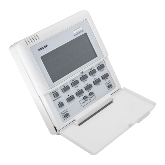
- Page 1 I NSTALLATION AND OPERATION MANUAL SMART CENTRALIZED CONTROLLER SCC-16...
- Page 2 “Original instructions” ...
- Page 3 User Notice • All indoor units must be powered uniformly. • Never place the wired control under direct sunlight or damp circumstances (like a laundry) and the wired controller shall be in accordance with national wiring regulations. • Provided that the air conditioner is installed where it would be affected by electromagnetic interference, the signal line and communication line must be shielded twist pairs.
-
Page 4: Table Of Contents
Content 1.General Introduction ..................1 1.1 Function Introduction ....................1 1.2 Communication Network ..................1 1.2.1 Units Connection ........................ 1 2. LCD.........................2 2.1 Outline of the LCD ....................2 2.2 Introduction to Symbols on the LCD ..............3 3. Buttons ......................4 3.1 Outline of Buttons ....................4 4.Control Flow Chart ..................5 5. - Page 5 5.3.6 Time ........................... 16 5.3.7 Shield ..........................18 5.3.8 Child Lock ......................... 25 5.3.9 Switchover between Celsius and Fahrenheit ..............26 6. Error Display ....................26 7. Installation and Debugging ................29 7.1 Installation ......................29 7.1.1 Installation Dimension Diagram ..................29 7.1.2 Interfaces ........................... 29 7.1.3 Preparation and Connection of the Communication Line ..........
-
Page 6: General Introduction
1.General Introduction 1.1 Function Introduction This smart centralized controller is intended for New UNI DC Inverter Series, capable of controlling up to 16 sets of units with maximum of 16 indoor units. Through this smart centralized controller, it is available to view and control those running parameters of the indoor unit, including on/off, running mode, fan speed etc, and also perform the single control and centralized control, further, it also can set the weekly timer and long-distance shielding to realize convenient control to the air conditioning system. -
Page 7: Lcd
2. LCD 2.1 Outline of the LCD Fig.2.1 Outline of the LCD 2.2 Introduction to Symbols on the LCD Fig.2.2 Introduction to Symbols on the LCD... - Page 8 Table 2.1 Introduction to the Symbols on the LCD Name Description It displays the fan speed of the indoor unit, high, medium, low and Fan speed auto. It displays the running mode of the indoor unit, auto, cool, dry, fan Running mode and heat.
-
Page 9: Buttons
3. Buttons 3.1 Outline of Buttons All on/All off All on/All off AUTO TUE WED THU FRI SAT ROOM SET INNER UNIT TEMP CHLD LOCK SHIELD MODE ERROR ON/OFF SUNM ON TUEW ED THUF RI SAT 1 2 34 CENTER 10 12 14 16 18 20 22 24 9 10 11 12 13 14 15 16 Mode... -
Page 10: Control Flow Chart
It is used to deactivate some or all functions of a single or a group the indoor Shield unit(s). All on/All off It is used to start/stop all indoor units. 4.Control Flow Chart See the following figure for the control flow chart of the smart centralized controller. Fig. -
Page 11: Viewing Of The Running Status Of The Indoor Unit And Control Mode
5. Viewing of the Running Status of the Indoor Unit and Control Mode 5.1 Viewing of the Running Status of the Indoor Unit It can be seen generally on the LCD that the minimum code of the online indoor unit flashes, with its running status, set temperature, and shield status etc. -
Page 12: Centralized Control
Thirty seconds later after the control command is sent out, the set parameters of the indoor unit will be displayed. See Fig. 5.2 for the temperature control under the single control: All on/ All off All on/ All off All on/ All off All on/ All off AUTO AUTO... -
Page 13: All On/All Off
See Fig. 5.4 for the centralized control to the temperature: Fig.5.4 Centralized Temperature Control For other settings, please refer to the following sections. 5.2.3 All on/All off In any case, the current indoor unit which is on/off will be turned off/on by pressing “All on/All off” with “CENTER”... -
Page 14: Mode
5.3.2 Mode Under the on state of the unit, whenever it is in single or centralized control, the running mode will change circularly as the following sequence by pressing “Mode”. Cool Heat See Fig.5.5 for how to set the running mode: Al l on /Al l off Al l on /Al l off AUTO... -
Page 15: Fan
5.3.4 Fan Under the on state of the unit, whenever it is in single or centralized control, the fan speed will change circularly as the following sequence by pressing “Fan”. See Fig.5.7 for how to set the fan speed: Auto M edium High All on/All off... - Page 16 5.3.5.1 How to Set the Weekly Timer under the Single Control It is available to go to the weekly timer setting page by pressing “Timer/Time” under the single control mode, with “*” flashing (“*” indicates MON, TUE, WED, THU, FRI, SAT, or SUN), and then press the week day button to set the week day.
- Page 17 (continued) Fig.5.8 How to Set the Weekly Timer under the Single Control 5.3.5.2 How to Cancel the Weekly Timer under the Single Control It is available to go to the weekly timing setting page by pressing “Timer/Time” under the single control mode, with “*”flashing (“*”...
-
Page 18: Time
(continued) Fig.5.9 How to Cancel the Weekly Timer under the Single Control 5.3.5.3 How to Set the Weekly Timer under the Centralized Control It is available to go to the weekly timing setting page by pressing “Timer/Time” under the single control mode , with “*”... - Page 20 (continued) Al l on / Al l off Al l on / Al l off AUTO TUE WED THU FRIS AT ROOM ROOM S SET INNER UNIT TEMP CH LD LOCK SHIELD MODE ERROR ON/OFF 1 2 34 SUNM ON TUEW ED THUF RI SAT CENTER 10 12 14 16 18 20 22 24 10 12 14 16 18 20 22 24...
- Page 21 (continued) All on/All off All on/All off All on/All off All on/All off AUTO AUTO TUE WED THU FRI SAT TUE WED THU FRI SAT ROOM ROOM SET INNER UNIT TEMP CH LD LOCK ROOM ROOM SET INNER UNIT SHIELD TEMP MODE ERROR...
- Page 22 All on/ All off All on/ All off All on/ All off All on/ All off AUTO AUTO TUE WED THU FRI SAT TUE WED THU FRI SAT ROOM ROOM SET INNER UNIT TEMP ROOM ROOM SET INNER UNIT TEMP CH LD LOCK CH LD LOCK SHIELD...
-
Page 23: Shield
5.3.7 Shield The shield function can be set under either single control or the centralized control, and the control command (including: On/Off, Mode, Fan, ▲/ ▼, and Shield etc.) based on the settings of the current indoor unit will be sent out to all online indoor units 2.5 seconds later. 5.3.7.1 “TEMP”... - Page 24 5.3.7.2 “MODE” Shield under the Single Control It is available to activate or deactivate the mode shield: first press “Shield” with “SHIELD” displayed on the LCD, next press it to switch to “MODE”, and then press “Confirm/Cancel”, after that, “MODE” will go on or go out but with “ON/OFF”...
- Page 25 Fig.5.15 “ON/OFF” Shield under the Singe Control 5.3.7.4 “ALL” Shield under the Single Control It is available to activate or deactivate the all shield: first press “Shield” with “SHIELD” displayed on the LCD, next press it to switch to “ALL”, and then press “Confirm/Cancel”, after that, “ON/OFF” will go on or go out and meanwhile quit this setting status.
- Page 26 All on/All off All on/All off All on/All off All on/All off AUTO AUTO TUE WED THU FRI SAT TUE WED THU FRI SAT ROOM ROOM SET INNER UNIT TEMP ROOM ROOM SET INNER UNIT TEMP CH LD LOCK CH LD LOCK SHIELD SHIELD MODE...
- Page 27 (continued) All on/All off All on/All off All on/All off All on/All off AUTO AUTO TUE WED THU FRI SAT TUE WED THU FRI SAT ROOM ROOM SET INNER UNIT TEMP TEMP ROOM ROOM SET INNER UNIT CH LD LOCK TEMP TEMP CH LD LOCK...
- Page 28 (continued) All on/All off All on/All off All on/All off All on/All off AUTO AUTO TUE WED THU FRI SAT TUE WED THU FRI SAT ROOM ROOM SET INNER UNIT TEMP SET INNER UNIT ROOM ROOM CH LD LOCK TEMP CH LD LOCK SHIELD SHIELD...
- Page 29 (continued) All on/All off All on/A l off All on/ All off All on/ A l off Quit this setting status automatically 30 Press “Confirm/Cancel” to seconds later or by pressing “Shield” activate / deactivate the shielding once. function. Fig.5.19 “ON/OFF” Shield under the Centralized Control 5.3.7.8 “ALL”...
-
Page 30: Child Lock
(continued) Press “Confirm/Cancel” to activate / deactivate the shielding function and meanwhile quit this setting status. Fig.5.20 “ALL” Shield under the Centralized Control Note: if the shield setting is not confirmed by pressing “Confirm/Cancel”, the system will quit this setting status 30 seconds later. -
Page 31: Switchover Between Celsius And Fahrenheit
5.3.9 Switchover between Celsius and Fahrenheit Under the off status of the current indoor unit, symbols of Celsius and Fahrenheit can be switched over by pressing “Mode” and “▼” simultaneously for five seconds. See Fig.5.22 for the switchover between Celsius and Fahrenheit: Fig.5.22 the Switchover between Celsius and Fahrenheit 6. - Page 32 Table 6.1 Errors for the New UNI DC Inverter Series Code Description Water pump error High pressure protection of the compressor Anti-freezing protection of the indoor unit Low pressure protection of the compressor High discharge temperature protection of the compressor Overload protection of the compressor Communication error Indoor unit fan protection...
-
Page 33: Installation And Debugging
7. Installation and Debugging 7.1 Installation 7.1.1 Installation Dimension Diagram Fig.7.1 Installation Dimensions Diagram 7.1.2 Interfaces See Fig.7.2 for the interfaces of the display board and see Fig.7.3 for the interfaces of the power supply module. +9.8V COM1 COM2 COM3 COM4 Fig.7.2 Interfaces of the Display Board Fig.7.3 Interfaces of the Power Supply Module Board... -
Page 34: Preparation And Connection Of The Communication Line
a. Interface of the Power Supply T he interface CN1 of the power supply module board is for the connection board of the external ① . power cord, the terminal AC-N for the neutral line, the terminal AC-L for the live line and the middle terminal keeps open. - Page 35 Fig.7.4 Concealed Cable Installation 1 (right-left wiring) Fig.7.5 Concealed Cable Installation 2 (up-down wiring) Fig. 7.6 Installation Diagram Serial No. Description Wall Power Supply Box (86) Bottom Base(including power supply module board) Screw Top Cover(including the display board ) After the installation, it is necessary to make the debugging to guarantee the normal communication.
-
Page 36: Unit Matching
7.2 Unit Matching Provided New UNI DC Inverter Series unit (one outdoor unit is matched with one indoor unit) is needed for some project, one smart zone control can control up to 16 indoor units. Example: Suppose that there are five outdoor units and five indoor units for some project, only one Smart centralized controller is needed. -
Page 37: Labeling
The press on “Confirm/Cancel” can confirm this debugging setting and go to the viewing state of the current indoor unit; otherwise this setting will not be saved. See Fig.7.7 for the debugging operation. Fig.7 shows the indoor unit 1 and indoor unit 2, both of which are connected with the port COM2. - Page 38 Room Name Child Room Bedroom Living Room Indoor Unit Address Port 1,Indoor Unit 04 Port 1, Indoor Unit 05 Port 1,Indoor Unit 06 Indoor Unit No. After get clear about the relationship of the indoor unit no. and the room, the user can write “Child Room”, “Bedroom”, “Living Room”...
- Page 40 SINCLAIR CORPORATION Ltd. 1-4 Argyll St. London W1F 7LD Great Britain www.sinclair-world.com This product was manufactured in China (Made in China). REPRESENTATIVE SINCLAIR EUROPE spol. s r.o. Purkynova 45 612 00 Brno Czech Republic TECHNICAL SUPPORT NEPA spol. s r.o. Purkynova 45...