Table of Contents
Advertisement
Operator's Manual
7-1/4 in. SLIDING COMPOUND
MITER SAW WITH LASER TRAC
Model No. 137.211940
CAUTION:
Before using this Miter Saw,
read this manual and follow
all its Safety Rules and
Operating Instructions
Customer Help Line
For Technical Support
1-800-843-1682
Sears, Roebuck and Co., Hoffman Estates, lL 60179 USA
Visit our Craftsman website: www.sears.com/craftsman
Part No. 137211940001
®
●
●
●
●
●
Sears Parts &
Repair Center
1-800-488-1222
1
Safety Instructions
Installation
Operation
Maintenance
Parts List
Printed in China
Advertisement
Table of Contents

Related Manuals for Craftsman 137.21194


Summary of Contents for Craftsman 137.21194
- Page 1 Safety Rules and Operating Instructions Customer Help Line For Technical Support 1-800-843-1682 Sears, Roebuck and Co., Hoffman Estates, lL 60179 USA Visit our Craftsman website: www.sears.com/craftsman Part No. 137211940001 ® Safety Instructions ● Installation ●...
-
Page 2: Table Of Contents
Troubleshooting Guide ... Parts List ... CRAFTSMAN ONE YEAR FULL WARRANTY If this Craftsman tool fails due to a defect in material or workmanship within one year from the date of purchase, call 1-800-4-MY-HOME free repair (or replacement if repair proves impossible). -
Page 3: Product Specifications
PRODUCT SPECIFICATIONS MOTOR Power Source ... 9Amp, 120V AC, 60Hz Speed ... 5000 RPM (No load) Brake ... Electric Double Insulated ... Yes BLADE SIZE Diameter... 7-1/4 in. Arbor size... 5/8 in. ROTATING TABLE: Diameter... 9-1/32 in. Miter Detent Stops ... 0, 15, 22.5, 31.6, 45º R & L Bevel Positive Stops ... -
Page 4: Symbols
WARNING ICONS Your power tool and its Operator’s Manual may contain “WARNING ICONS” (a picture symbol intended to alert you to, and/or instruct you how to avoid, a potentially hazardous condition). Understanding and heeding these symbols will help you operate your tool better and safer. Shown below are some of the symbols you may see. -
Page 5: Power Tool Safety
POWER TOOL SAFETY GENERAL SAFETY INSTRUCTIONS BEFORE USING THIS POWER TOOL Safety is a combination of common sense, staying alert and knowing how to use your power tool. CAUTION To avoid mistakes that could cause serious injury, do not plug the tool in until you have read and understood the following. - Page 6 Follow instructions for lubricating and changing accessories. 23. WARNING: Dust generated from certain materials can be hazardous to your health. Always operate saw in well-ventilated area and provide for proper dust removal. DANGER electronic devices, such as...
-
Page 7: Compound Miter Saw Safety
COMPOUND MITER SAW SAFETY SPECIFIC SAFETY INSTRUCTIONS FOR THIS COMPOUND MITER SAW 1. DO NOT operate the miter saw until it is completely assembled and installed according to these instructions. 2. IF YOU ARE NOT thoroughly familiar with the operation of miter... - Page 8 fingers to be within 6-3/4 in. of the saw blade the workpiece is too small. 22. PROVIDE adequate support to the sides of the saw table for long work pieces. 23. NEVER use the miter saw in an area with flammable liquids or gases.
-
Page 9: Electrical Requirements And Safety
1. Connect this saw to a 120 V circuit. This circuit must not be less than a #18 wire with a 9 A time lag fuse. - Page 10 For heavy loads, the voltage at motor terminals must equal the voltage specified on the nameplate. c. IMPROPER or dull saw blades are used. 5. Most motor troubles may be traced to loose or incorrect connections, overload, low voltage or inadequate power supply wiring.
-
Page 11: Accessories And Attachments
Use of improper accessories may cause hazards. ● The use of any cutting tool except 7-1/4 in. saw blades which meet the requirements under recommended accessories is prohibited. Do not use accessories such as shaper cutters or dado sets. Ferrous metal cutting and the use of abrasive wheels is prohibited. -
Page 12: Tools Needed For Assembly
TOOLS NEEDED FOR ASSEMBLY Supplied Blade Wrench COMBINATION SQUARE MUST BE TRUE Should not gap or overlap when square is flipped over (see dotted figure). Draw light line on board along this edge. Should not gap or overlap when square flipped over (see dotted figure). -
Page 13: Carton Contents
This cord must remain unplugged whenever you are working on the saw. 1. Remove the miter saw from the carton. IMPORTANT: Do not lift miter saw by the trigger switch handle. It may cause misalignment. Only lift machine by the base hand holds. -
Page 14: Know Your Sliding Compound Miter Saw
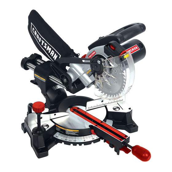
KNOW YOUR SLIDING COMPOUND MITER SAW Upper blade guard Bevel lock handle Hold-down clamp Mounting hole Lower blade guard Saw blade Positive stop locking lever Turntable Laser ON/OFF switch Positive miter detent Switch handle ON/OFF trigger switch Motor Laser guide... -
Page 15: Glossary Of Terms
MITER HANDLE – Used to rotate the table, and to rotate the saw to a right or left cutting position. MITER SCALE – Measures the miter angle 0° to 45° left and right. - Page 16 POSITIVE STOP LOCKING LEVER – Locks the miter saw at a preset positive stop for the desired miter angle. SWITCH HANDLE – The switch handle contains the trigger switch and the laser on/off switch. The blade is lowered into the workpiece by pushing down on the handle.
-
Page 17: Assembly And Adjustments
ASSEMBLY AND ADJUSTMENTS WARNING To avoid injury, do not connect this miter saw to the power source until it is completely assembled and adjusted, and you have read and understood this Operator’s Manual. INSTALLING THE SUPPORT BRACKET (FIG. A) 1. Place the support bracket (1) in front of the miter saw as shown. - Page 18 (3) when not in use. Fig. E UNLOCKING THE SLIDE CARRIAGE (FIG. F) After removing the saw from the carton, loosen the slide carriage lock knob (1). When transporting or storing the miter saw, the slide carriage should always be locked in position.
- Page 19 ● Lock the slide carriage in place by tightening the slide carriage lock knob. ● To avoid back injury, lift the saw by using the designated carrying handles located on the top of the machine. When lifting, bend at your knees, not from your back.
-
Page 20: Mounting Instructions
The base of the saw has four mounting holes. Bolt the base of the miter saw (1) to the work surface (5), using the fastening method as shown in Fig I. Fig. I 1. - Page 21 Fig. M INSTALLING BLADE (FIG. K, L, M) WARNING Un-plug the miter saw before changing/installing the blade. 1. Install a 7-1/4 in. blade with a 5/8 in. arbor making sure the rotation arrow on the blade matches the...
- Page 22 Class II laser ® beam. The laser beam will enable you to preview the saw blade path on the stock to be cut before starting the miter saw. This laser guide is powered by the transformed alternating current supply directly through the power lead.
- Page 23 2. Place a combination square (2) on the miter table with the ruler against the table and the heel of the square against the saw blade. 3. If the blade is not 90 with the miter table (5), loosen the...
- Page 24 The sliding compound miter saw scale can be easily read, showing miter angles from 0° to 45° to the left, and 0° to 45° to the right. The miter saw table has nine of the most common angle setttings with positive stops at 0°, 15°, 22.5°, 31.6°, and 45°.
- Page 25 (1) with a 6mm hex wrench. 4. Adjust the fence 90° to the blade and tighten the four fence locking bolts. CAUTION: If the saw has not been used recently, recheck blade squareness to the fence and readjust if needed.
-
Page 26: Operation
● Keep all guards in place, in working order and proper adjustment. If any part of this miter saw is missing, bent, damaged or broken in any way, or any electrical parts do not work, turn the saw off and unplug it. - Page 27 flammable liquids, vapors, or gases. ● Plan ahead to protect your eyes, hands, face and ears. ● Know your miter saw. Read and understand the Operator’s Manual and labels affixed to the tool. Learn its application and limitations as well as the specific potential hazards...
- Page 28 ● Do not use this saw to cut small pieces. If the workpiece being cut would cause your hand or fingers to be within 6-3/4 inches of the saw blade the workpiece is too small.
- Page 29 Make sure bystanders are clear of the saw and workpiece. Do not force the saw. It will do the job better and safer at its designed rate. Starting a cut: ●...
- Page 30 Disconnect master switches. Store tool away from children and other unqualified users. WARNING To avoid injury from materials being thrown, always unplug the saw to avoid accidental starting, and remove small pieces of material from the table cavity. MITER CUT (FIG. X) 1.
- Page 31 BEVEL CUT (FIG. Y) 1. When a bevel cut is required, loosen the bevel lock handle (1) by turning it clockwise. 2. Tilt the cutting head to the desired angle, as shown on the bevel scale (2). 3. The blade can be positioned at any angle, from a 90°...
- Page 32 4. Grasp and pull forward the switch handle (2) until the center of the saw blade is over the front of the workpiece (3). 5. Engage the trigger to turn the saw 6. When the saw reaches full speed,...
- Page 33 When making multiple or repetitive cuts that result in cut-off pieces of one inch or less, it is possible for the saw blade to catch the cut-off piece and throw it out of the saw or into the blade guard and housing, possibly causing damage or injury.
- Page 34 CUTTING BASE MOLDING (FIG. FF) Base moldings and many other moldings can be cut on a compound miter saw. The setup of the saw depends on molding characteristics and application, as shown. Perform practice cuts on scrap material to achieve best results: 1.
- Page 35 Bevel/Miter Settings BEVEL MITER SETTING SETTING 33.9° 31.6° Right 1. Position top of molding against fence. 33.9° 31.6° Left 33.9° 31.6° Left 33.9° 31.6° Right 1. Position top of molding against fence. TYPE OF CUT 2. Miter table set at RIGHT 31.6°. 3.
-
Page 36: Crown Molding Chart
CROWN MOLDING CHART Compound Miter saw Miter and bevel Angle settings Wall to Crown Molding Angle 52/38° Crown Molding Angle Miter Bevel Between Setting Setting Walls 42.93 41.08 42.39 40.79 41.85 40.50 41.32 40.20 40.79 39.90 40.28 39.61 39.76 39.30 39.25... -
Page 37: Maintenance
Fig. II LOWER BLADE GUARD Do not use the saw without the lower blade guard. The lower blade guard is attached to the saw for your protection. Should the lower guard become damaged, do not use the saw until the damaged guard has been replaced. - Page 38 SAWDUST Periodically, sawdust will accumulate under the work table and base. This could cause difficulty in the movement of the worktable when setting up a miter cut. Frequently blow out or vacuum up the sawdust. WARNING Wear proper eye protection to keep debris from entering eyes when removing sawdust from unit.
-
Page 39: Troubleshooting Guide
TROUBLESHOOTING GUIDE WARNING To avoid injury from accidental starting, always turn switch OFF and unplug the tool before moving, replacing the blade or making adjustments. TROUBLESHOOTING GUIDE - MOTOR PROBLEM PROBLEM CAUSE Brake does 1. Motor brushes not sealed not stop blade or lightly sticking. - Page 40 2. Dull or warped blade. wood. 3. Improper blade size. 4 Wood is moving during cut. Saw vibrates or 1. Saw blade not round / shakes. damaged / loose. 2. Arbor bolt loose. SUGGESTED CORRECTIVE ACTION 1. See ADJUSTMENT -Setting Cutting Depth section.
-
Page 41: Parts List
7-1/4 in. COMPOUND MITER SAW WARNING When servicing use only CRAFTSMAN replacement parts. Use of any other parts many create a HAZARD or cause product damage. Any attempt to repair or replace electrical parts on this Miter Saw may create a HAZARD unless repair is done by a qualified service technician. - Page 42 7-1/4 in. COMPOUND MITER SAW SCHEMATIC MODEL NO. 137.211940...
- Page 43 7-1/4 in. COMPOUND MITER SAW PARTS LIST FOR MOTOR I.D. Description 0HX7 NEEDLE ROLLER BEARING 0JX2 HEX. SOC. SET SCREW 0KCP CR. RE. PAN HEAD TAPPING & WASHER SCREW 0KNE HEX. NUT 0QBE BRUSH HOLDER ASS’Y 0QBG CARBON BRUSH ASS’Y...
- Page 44 Get it fixed, at your home or ours! For expert troubleshooting and home solutions advice: For repair – in your home – of all major brand appliances, lawn and garden equipment, or heating and cooling systems, no matter who made it, no matter who sold it! For the replacement parts, accessories and owner’s manuals that you need to do-it-yourself.