
Related Manuals for Nokia RM-364


Summary of Contents for Nokia RM-364
- Page 1 Nokia Customer Care Service Manual RM-364 (Nokia 3120 classic; L3&4) Mobile Terminal Part No: (Issue 1) COMPANY CONFIDENTIAL Copyright © 2008 Nokia. All rights reserved.
- Page 2 RM-364 Amendment Record Sheet Amendment Record Sheet Amendment No Date Inserted By Comments Issue 1 04/2008 Page ii COMPANY CONFIDENTIAL Issue 1 Copyright © 2008 Nokia. All rights reserved.
- Page 3 Nokia operates a policy of continuous development. Nokia reserves the right to make changes and improvements to any of the products described in this document without prior notice. Under no circumstances shall Nokia be responsible for any loss of data or income or any special, incidental, consequential or indirect damages howsoever caused.
- Page 4 WCDMA networks and cause problems to 3G cellular phone communication in a wide area. • During testing never activate the GSM or WCDMA transmitter without a proper antenna load, otherwise GSM or WCDMA PA may be damaged. Page iv COMPANY CONFIDENTIAL Issue 1 Copyright © 2008 Nokia. All rights reserved.
- Page 5 Use only approved accessories and batteries. Do not connect incompatible products. CONNECTING TO OTHER DEVICES When connecting to any other device, read its user’s guide for detailed safety instructions. Do not connect incompatible products. Issue 1 COMPANY CONFIDENTIAL Page v Copyright © 2008 Nokia. All rights reserved.
- Page 6 All of the above suggestions apply equally to the product, battery, charger or any accessory. Page vi COMPANY CONFIDENTIAL Issue 1 Copyright © 2008 Nokia. All rights reserved.
- Page 7 RM-364 ESD protection ESD protection Nokia requires that service points have sufficient ESD protection (against static electricity) when servicing the phone. Any product of which the covers are removed must be handled with ESD protection. The SIM card can be replaced without ESD protection if the product is otherwise ready for use.
- Page 8 Batteries' performance is particularly limited in temperatures well below freezing. Do not dispose of batteries in a fire! Dispose of batteries according to local regulations (e.g. recycling). Do not dispose as household waste. Page viii COMPANY CONFIDENTIAL Issue 1 Copyright © 2008 Nokia. All rights reserved.
- Page 9 Our policy is of continuous development; details of all technical modifications will be included with service bulletins. While every endeavour has been made to ensure the accuracy of this document, some errors may exist. If any errors are found by the reader, NOKIA MOBILE PHONES Business Group should be notified in writing/e- mail. Please state: •...
- Page 10 RM-364 Company Policy (This page left intentionally blank.) Page x COMPANY CONFIDENTIAL Issue 1 Copyright © 2008 Nokia. All rights reserved.
- Page 11 RM-364 Nokia 3120 classic; L3&4 Service Manual Structure Nokia 3120 classic; L3&4 Service Manual Structure 1 General information 2 Service Devices and Service Concepts 3 BB Troubleshooting and Manual Tuning Guide 4 RF troubleshooting 5 System Module Description Glossary Issue 1...
- Page 12 RM-364 Nokia 3120 classic; L3&4 Service Manual Structure (This page left intentionally blank.) Page xii COMPANY CONFIDENTIAL Issue 1 Copyright © 2008 Nokia. All rights reserved.
- Page 13 Nokia Customer Care 1 — General information Issue 1 COMPANY CONFIDENTIAL Page 1 –1 Copyright © 2008 Nokia. All rights reserved.
- Page 14 RM-364 General information (This page left intentionally blank.) Page 1 –2 COMPANY CONFIDENTIAL Issue 1 Copyright © 2008 Nokia. All rights reserved.
-
Page 15: Table Of Contents
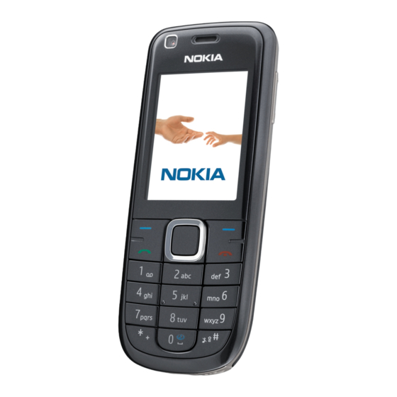
Table 3 Headsets ..............................1–7 Table 4 Data cables ..............................1–7 Table 5 Memory cards ............................1–7 List of Figures Figure 1 RM-364 (Nokia 3120 classic) product picture ..................1–5 Issue 1 COMPANY CONFIDENTIAL Page 1 –3 Copyright © 2008 Nokia. All rights reserved. - Page 16 RM-364 General information (This page left intentionally blank.) Page 1 –4 COMPANY CONFIDENTIAL Issue 1 Copyright © 2008 Nokia. All rights reserved.
-
Page 17: Product Selection
RM-364 General information Product selection RM-364 (Nokia 3120 classic) is a GSM/WCDMA dual mode phone, supporting EGSM850/900/1800/1900 and WCDMA850/2100. Figure 1 RM-364 (Nokia 3120 classic) product picture Phone features Display and keypad features • 2.0” 240x320 pixel, 16M true colour display •... -
Page 18: User Interface And Software Features
• Nokia PC Suite Accessories Sales package contents • Nokia 3120 classic phone • Nokia Battery BL-4U • Nokia Charger AC-3 • Nokia Wired headset HS-40 • User Guide Page 1 –6 COMPANY CONFIDENTIAL Issue 1 Copyright © 2008 Nokia. All rights reserved. -
Page 19: Table 1 Battery And Chargers
Table 1 Battery and chargers Type Name Note: This phone is charged through the smaller charger Nokia standard interface (2.0 mm plug). The 3.5 mm standard charger can be used together with the CA-44 charger adapter. BL-4U Battery 1000 mAh Li-Ion... -
Page 20: Technical Specifications
WCDMA I (2100): -50 ... +24 dBm/0.01μW ... 251.2mW Number of RF channels GSM850: 124 GSM900: 174 GSM1800: 374 GSM1900: 299 WCDMA V (850): 108 WCDMA I (2100): 277 Channel spacing 200 kHz Page 1 –8 COMPANY CONFIDENTIAL Issue 1 Copyright © 2008 Nokia. All rights reserved. -
Page 21: General Specifications
No storage. An attempt to operate <-40 C and >+85 storage may cause permanent damage Charging allowed C ... +55 Long term storage C ... +85 conditions Issue 1 COMPANY CONFIDENTIAL Page 1 –9 Copyright © 2008 Nokia. All rights reserved. - Page 22 Condensed or dripping water may cause intermittent malfunctions. Protection against dripping water has to be implemented in (enclosure) mechanics. Continuous dampness will cause permanent damage to the module. Page 1 –10 COMPANY CONFIDENTIAL Issue 1 Copyright © 2008 Nokia. All rights reserved.
- Page 23 Nokia Customer Care 2 — Service Devices and Service Concepts Issue 1 COMPANY CONFIDENTIAL Page 2 –1 Copyright © 2008 Nokia. All rights reserved.
- Page 24 RM-364 Service Devices and Service Concepts (This page left intentionally blank.) Page 2 –2 COMPANY CONFIDENTIAL Issue 1 Copyright © 2008 Nokia. All rights reserved.
-
Page 25: Table Of Contents
Figure 5 Module jig service concept ........................2–17 Figure 6 RF testing concept with RF coupler ....................2–18 Figure 7 Service concept for RF testing and RF/BB tuning ................2–19 Issue 1 COMPANY CONFIDENTIAL Page 2 –3 Copyright © 2008 Nokia. All rights reserved. - Page 26 RM-364 Service Devices and Service Concepts (This page left intentionally blank.) Page 2 –4 COMPANY CONFIDENTIAL Issue 1 Copyright © 2008 Nokia. All rights reserved.
-
Page 27: Service Devices
The table below gives a short overview of service devices that can be used for testing, error analysis, and repair of product RM-364. For the correct use of the service devices, and the best effort of workbench setup, please refer to various concepts. -
Page 28: General Devices
The table below gives a short overview of service devices that can be used for testing, error analysis, and repair of product RM-364. For the correct use of the service devices, and the best effort of workbench setup, please refer to various concepts. - Page 29 4 Connect an FBUS cable (if necessary). 5 Start Phoenix service software. Note: Phoenix enables CU-4 regulators via USB when it is started. Reconnecting the power supply requires a Phoenix restart. Issue 1 COMPANY CONFIDENTIAL Page 2 –7 Copyright © 2008 Nokia. All rights reserved.
- Page 30 PK-1 is meant for use with a PC that does not have a series interface. To use this USB dongle for security service functions please register the dongle in the same way as the PKD-1 series dongle. Page 2 –8 COMPANY CONFIDENTIAL Issue 1 Copyright © 2008 Nokia. All rights reserved.
- Page 31 The SB-6 test box is a generic device to perform Bluetooth bit error rate testing and doing cordless FBUS connection via Bluetooth. SPS-2 Soldering paste spreader Issue 1 COMPANY CONFIDENTIAL Page 2 –9 Copyright © 2008 Nokia. All rights reserved.
- Page 32 The camera removal tool SS-88 is used to remove/attach the front camera module from/to the socket. SS-93 Blue stick tool SS-93 is used for general disassembly and assembly tasks. Page 2 –10 COMPANY CONFIDENTIAL Issue 1 Copyright © 2008 Nokia. All rights reserved.
-
Page 33: Cables
The table below gives a short overview of service devices that can be used for testing, error analysis, and repair of product RM-364. For the correct use of the service devices, and the best effort of workbench setup, please refer to various concepts. -
Page 34: Ca-35S
XCS-4 Modular cable XCS-4 is a shielded (one specially shielded conductor) modular cable for flashing and service purposes. Page 2 –12 COMPANY CONFIDENTIAL Issue 1 Copyright © 2008 Nokia. All rights reserved. - Page 35 The RF cable is used to connect, for example, a module repair jig to the RF measurement equipment. SMA to N-Connector ca. 610mm. Attenuation for: • GSM850/900: 0.3+-0.1 dB • GSM1800/1900: 0.5+-0.1 dB • WLAN: 0.6+-0.1dB Issue 1 COMPANY CONFIDENTIAL Page 2 –13 Copyright © 2008 Nokia. All rights reserved.
-
Page 36: Service Concepts
Figure 2 POS flash concept Type Description Product specific tools BL-4U Battery Other tools FLS-5 POS flash dongle PC with Phoenix service software Cables DKE-2 USB connectivity cable Page 2 –14 COMPANY CONFIDENTIAL Issue 1 Copyright © 2008 Nokia. All rights reserved. -
Page 37: Flash Concept With Fps-10
Other devices FPS-10 Flash prommer box PKD-1/PK-1 SW security device SS-46 Interface adapter PC with Phoenix service software Cables XCS-4 Modular cable CA-35S Power cable USB cable Issue 1 COMPANY CONFIDENTIAL Page 2 –15 Copyright © 2008 Nokia. All rights reserved. -
Page 38: Flash Concept With Fps-10
SW security device SS-62 Flash adapter base SX-4 Smart card PC with Phoenix service software Cables PCS-1 Power cable XCS-4 Modular cable Standard USB cable USB cable Page 2 –16 COMPANY CONFIDENTIAL Issue 1 Copyright © 2008 Nokia. All rights reserved. -
Page 39: Module Jig Service Concept
SW security device SX-4 Smart card PC with VPOS and Phoenix service software Measurement equipment Cables PCS-1 DC power cable XCS-4 Modular cable XRF-1 RF cable USB cable Issue 1 COMPANY CONFIDENTIAL Page 2 –17 Copyright © 2008 Nokia. All rights reserved. -
Page 40: Rf Testing Concept With Rf Coupler
SX-4 Smart card FPS-10 Flash prommer box PKD-1/PK-1 SW security device SS-62 Flash adapter base Measurement equipment PC with Phoenix service software Cables PCS-1 Power cable Page 2 –18 COMPANY CONFIDENTIAL Issue 1 Copyright © 2008 Nokia. All rights reserved. -
Page 41: Service Concept For Rf Testing And Rf/Bb Tuning
Product specific devices MJ-164 Module jig Other devices CU-4 Control unit PK-1 SW security device SX-4 Smart card Measurement equipment Smart card reader PC with Phoenix service software Issue 1 COMPANY CONFIDENTIAL Page 2 –19 Copyright © 2008 Nokia. All rights reserved. - Page 42 RM-364 Service Devices and Service Concepts Type Description Cables DAU-9S MBUS cable PCS-1 DC power cable XRS-6 RF cable GPIB control cable USB cable Page 2 –20 COMPANY CONFIDENTIAL Issue 1 Copyright © 2008 Nokia. All rights reserved.
- Page 43 Nokia Customer Care 3 — BB Troubleshooting and Manual Tuning Guide Issue 1 COMPANY CONFIDENTIAL Page 3 –1 Copyright © 2008 Nokia. All rights reserved.
- Page 44 RM-364 BB Troubleshooting and Manual Tuning Guide (This page left intentionally blank.) Page 3 –2 COMPANY CONFIDENTIAL Issue 1 Copyright © 2008 Nokia. All rights reserved.
- Page 45 Earpiece troubleshooting ......................... 3–46 IHF troubleshooting ..........................3–47 Microphone troubleshooting ........................3–48 Vibra troubleshooting............................ 3–49 Baseband manual tuning guide......................... 3–49 Certificate restoring for BB5 products......................3–49 Issue 1 COMPANY CONFIDENTIAL Page 3 –3 Copyright © 2008 Nokia. All rights reserved.
- Page 46 Figure 11 Differential output waveform of the Ext_in_IHF_out out loop measurement when speaker is connected..............................3–39 Figure 12 Single-ended output waveform of the HP_in_Ext_out loop when microphone is connected. 3–40 Page 3 –4 COMPANY CONFIDENTIAL Issue 1 Copyright © 2008 Nokia. All rights reserved.
-
Page 47: Baseband Self Tests In Phoenix
Always start the troubleshooting procedure by running the Phoenix self tests. If a test fails, please follow the diagram below. Dead or jammed device troubleshooting. If the phone is dead and you cannot perform the self tests, go to Issue 1 COMPANY CONFIDENTIAL Page 3 –5 Copyright © 2008 Nokia. All rights reserved. - Page 48 RM-364 BB Troubleshooting and Manual Tuning Guide Troubleshooting flow Page 3 –6 COMPANY CONFIDENTIAL Issue 1 Copyright © 2008 Nokia. All rights reserved.
-
Page 49: Power And Charging Troubleshooting
RM-364 BB Troubleshooting and Manual Tuning Guide Power and charging troubleshooting Dead or jammed device troubleshooting Troubleshooting flow Issue 1 COMPANY CONFIDENTIAL Page 3 –7 Copyright © 2008 Nokia. All rights reserved. - Page 50 RM-364 BB Troubleshooting and Manual Tuning Guide Troubleshooting flow Page 3 –8 COMPANY CONFIDENTIAL Issue 1 Copyright © 2008 Nokia. All rights reserved.
-
Page 51: General Power Checking
Accessory connected VCAM_2V8 LP3987ITLX-2. 2.850 Camera Disabled in 85/N3351 sleep VCAM_1V8 LM3677TLX-1. 1.800 Camera Disabled in 82/L1000 sleep VSIM2_MMC KMBGN000A/ Internal Disabled in L1001 memory sleep Issue 1 COMPANY CONFIDENTIAL Page 3 –9 Copyright © 2008 Nokia. All rights reserved. -
Page 52: Charging Troubleshooting
RM-364 BB Troubleshooting and Manual Tuning Guide Charging troubleshooting Troubleshooting flow Page 3 –10 COMPANY CONFIDENTIAL Issue 1 Copyright © 2008 Nokia. All rights reserved. -
Page 53: Interface Troubleshooting
RM-364 BB Troubleshooting and Manual Tuning Guide Interface troubleshooting Flash programming fault troubleshooting Part 1 Issue 1 COMPANY CONFIDENTIAL Page 3 –11 Copyright © 2008 Nokia. All rights reserved. - Page 54 RM-364 BB Troubleshooting and Manual Tuning Guide Part 2 Figure 8 Flashing pic 1. Take single trig measurement for the rise of the BSI signal. Page 3 –12 COMPANY CONFIDENTIAL Issue 1 Copyright © 2008 Nokia. All rights reserved.
- Page 55 RM-364 BB Troubleshooting and Manual Tuning Guide Figure 9 Flashing pic 2. Take single trig measurement for the rise of the BSI signal. Issue 1 COMPANY CONFIDENTIAL Page 3 –13 Copyright © 2008 Nokia. All rights reserved.
-
Page 56: Combo Memory Troubleshooting
RM-364 BB Troubleshooting and Manual Tuning Guide Combo memory troubleshooting Troubleshooting flow Page 3 –14 COMPANY CONFIDENTIAL Issue 1 Copyright © 2008 Nokia. All rights reserved. -
Page 57: Sd Card Troubleshooting
RM-364 BB Troubleshooting and Manual Tuning Guide SD card troubleshooting Troubleshooting flow Issue 1 COMPANY CONFIDENTIAL Page 3 –15 Copyright © 2008 Nokia. All rights reserved. -
Page 58: Usb Interface Troubleshooting
RM-364 BB Troubleshooting and Manual Tuning Guide USB interface troubleshooting Troubleshooting flow Page 3 –16 COMPANY CONFIDENTIAL Issue 1 Copyright © 2008 Nokia. All rights reserved. -
Page 59: Sim Card Troubleshooting
RM-364 BB Troubleshooting and Manual Tuning Guide SIM card troubleshooting Troubleshooting flow Issue 1 COMPANY CONFIDENTIAL Page 3 –17 Copyright © 2008 Nokia. All rights reserved. -
Page 60: User Interface Troubleshooting
• Malfunction of several keys at the same time; this happens when one or more rows or columns in the key matrix are failing (shortcut or open connection). If the failure mode is not clear, start with the Keyboard test in Phoenix. Troubleshooting flow Page 3 –18 COMPANY CONFIDENTIAL Issue 1 Copyright © 2008 Nokia. All rights reserved. -
Page 61: Power Key Troubleshooting
• The display is in a normal mode when the phone is in active use. • Display is in a partial idle mode when the phone is in the screen saver mode. Issue 1 COMPANY CONFIDENTIAL Page 3 –19 Copyright © 2008 Nokia. All rights reserved. - Page 62 APE ID). 3. Proceed to the display troubleshooting flowcharts. Phoenix to find the detailed fault mode. Use the Display Test tool in Page 3 –20 COMPANY CONFIDENTIAL Issue 1 Copyright © 2008 Nokia. All rights reserved.
-
Page 63: Blank Display Troubleshooting
Context The phone is in normal mode and there is no image on the display. Display back light could be on in some cases. Troubleshooting flow Issue 1 COMPANY CONFIDENTIAL Page 3 –21 Copyright © 2008 Nokia. All rights reserved. -
Page 64: Faulty Image Troubleshooting
The image on the display is corrupted or part of the image is missing. If a part of the image is missing, change the display module. Otherwise, follow the flowchart below. Page 3 –22 COMPANY CONFIDENTIAL Issue 1 Copyright © 2008 Nokia. All rights reserved. - Page 65 RM-364 BB Troubleshooting and Manual Tuning Guide Troubleshooting flow Issue 1 COMPANY CONFIDENTIAL Page 3 –23 Copyright © 2008 Nokia. All rights reserved.
-
Page 66: Display On But No Image Troubleshooting
BB Troubleshooting and Manual Tuning Guide Display on but no image troubleshooting Context The phone is on, display active and blank, but no image. Troubleshooting flow Page 3 –24 COMPANY CONFIDENTIAL Issue 1 Copyright © 2008 Nokia. All rights reserved. -
Page 67: Keyboard Backlight Troubleshooting
Bad conditions often cause bad pictures. Therefore, the camera operation has to be checked in constant conditions or by using a second, known-to-be-good Nokia device as reference. Image quality is hard to measure quantitatively, and the difference between a good and a bad picture can be small. Some training or experience may be needed to detect what is actually wrong. - Page 68 • Analyse the picture from your PC monitor, full colour setting is recommended • If possible, compare with a picture of the same motive taken with a similar Nokia device • If camera has auto focus: Remember that the white focussing frame which appears when the camera button is pressed halfway down, must turn green for auto focus lock.
-
Page 69: Main Camera Troubleshooting
RM-364 BB Troubleshooting and Manual Tuning Guide Main camera troubleshooting Troubleshooting flow Issue 1 COMPANY CONFIDENTIAL Page 3 –27 Copyright © 2008 Nokia. All rights reserved. -
Page 70: Main Camera Bad Image Quality Troubleshooting
RM-364 BB Troubleshooting and Manual Tuning Guide Main camera bad image quality troubleshooting Troubleshooting flow Page 3 –28 COMPANY CONFIDENTIAL Issue 1 Copyright © 2008 Nokia. All rights reserved. -
Page 71: Main Camera Viewfinder Troubleshooting
RM-364 BB Troubleshooting and Manual Tuning Guide Main camera viewfinder troubleshooting Troubleshooting flow Issue 1 COMPANY CONFIDENTIAL Page 3 –29 Copyright © 2008 Nokia. All rights reserved. -
Page 72: Main Camera Hardware Failure Message Troubleshooting
RM-364 BB Troubleshooting and Manual Tuning Guide Main camera hardware failure message troubleshooting Troubleshooting flow Page 3 –30 COMPANY CONFIDENTIAL Issue 1 Copyright © 2008 Nokia. All rights reserved. -
Page 73: Main Camera Hardware Troubleshooting
RM-364 BB Troubleshooting and Manual Tuning Guide Main camera hardware troubleshooting Troubleshooting flow Camera LED flash troubleshooting Context Note: There are three different flash modes. Issue 1 COMPANY CONFIDENTIAL Page 3 –31 Copyright © 2008 Nokia. All rights reserved. -
Page 74: Secondary (Front) Camera Troubleshooting
BB Troubleshooting and Manual Tuning Guide Troubleshooting flow Secondary (front) camera troubleshooting Evaluating videocall picture quality from secondary camera When testing the picture quality of a videocall, remember the following: Page 3 –32 COMPANY CONFIDENTIAL Issue 1 Copyright © 2008 Nokia. All rights reserved. - Page 75 • The center of the picture is sharper than the edges • If possible, compare with the picture on another Nokia device in a videocall, and of the same motive. Issue 1 COMPANY CONFIDENTIAL Page 3 –33...
-
Page 76: Secondary Camera Bad Image Quality Troubleshooting
RM-364 BB Troubleshooting and Manual Tuning Guide Secondary camera bad image quality troubleshooting Troubleshooting flow Page 3 –34 COMPANY CONFIDENTIAL Issue 1 Copyright © 2008 Nokia. All rights reserved. -
Page 77: Secondary Camera Troubleshooting
RM-364 BB Troubleshooting and Manual Tuning Guide Secondary camera troubleshooting Troubleshooting flow Issue 1 COMPANY CONFIDENTIAL Page 3 –35 Copyright © 2008 Nokia. All rights reserved. -
Page 78: Secondary Camera Hardware Troubleshooting
RM-364 BB Troubleshooting and Manual Tuning Guide Secondary camera hardware troubleshooting Troubleshooting flow Page 3 –36 COMPANY CONFIDENTIAL Issue 1 Copyright © 2008 Nokia. All rights reserved. -
Page 79: Audio Troubleshooting
Earpiece, internal microphone and speaker are in place during measurement. Applying a headset accessory during measurement causes a significant drop in measured quantities. The gain values presented in the table apply for a differential output vs. single-ended/differential input. Issue 1 COMPANY CONFIDENTIAL Page 3 –37 Copyright © 2008 Nokia. All rights reserved. - Page 80 (OUT/GND) HSEAR R N and GND HSEAR P, HSEAR N and GND HSEAR R P, HSEAR R N and GND HSEAR P, HSEAR N and GND Page 3 –38 COMPANY CONFIDENTIAL Issue 1 Copyright © 2008 Nokia. All rights reserved.
- Page 81 If a special low-pass filter designed for measuring digital amplifiers is unavailable, the measurement must be performed with a current probe and the input signal frequency must be 2kHz. Figure 11 Differential output waveform of the Ext_in_IHF_out out loop measurement when speaker is connected. Issue 1 COMPANY CONFIDENTIAL Page 3 –39 Copyright © 2008 Nokia. All rights reserved.
- Page 82 RM-364 BB Troubleshooting and Manual Tuning Guide Figure 12 Single-ended output waveform of the HP_in_Ext_out loop when microphone is connected. Page 3 –40 COMPANY CONFIDENTIAL Issue 1 Copyright © 2008 Nokia. All rights reserved.
-
Page 83: Internal Earpiece Troubleshooting
RM-364 BB Troubleshooting and Manual Tuning Guide Internal earpiece troubleshooting Troubleshooting flow Issue 1 COMPANY CONFIDENTIAL Page 3 –41 Copyright © 2008 Nokia. All rights reserved. -
Page 84: Internal Microphone Troubleshooting
RM-364 BB Troubleshooting and Manual Tuning Guide Internal microphone troubleshooting Troubleshooting flow Page 3 –42 COMPANY CONFIDENTIAL Issue 1 Copyright © 2008 Nokia. All rights reserved. -
Page 85: Internal Handsfree (Ihf) Troubleshooting
RM-364 BB Troubleshooting and Manual Tuning Guide Internal handsfree (IHF) troubleshooting Troubleshooting flow Issue 1 COMPANY CONFIDENTIAL Page 3 –43 Copyright © 2008 Nokia. All rights reserved. -
Page 86: External Microphone Troubleshooting
RM-364 BB Troubleshooting and Manual Tuning Guide External microphone troubleshooting Troubleshooting flow Page 3 –44 COMPANY CONFIDENTIAL Issue 1 Copyright © 2008 Nokia. All rights reserved. -
Page 87: External Earpiece Troubleshooting
The phone should be dry and clean, and no objects must be located in such a way that they close any of the holes. Issue 1 COMPANY CONFIDENTIAL Page 3 –45 Copyright © 2008 Nokia. All rights reserved. -
Page 88: Earpiece Troubleshooting
RM-364 BB Troubleshooting and Manual Tuning Guide Earpiece troubleshooting Troubleshooting flow Page 3 –46 COMPANY CONFIDENTIAL Issue 1 Copyright © 2008 Nokia. All rights reserved. -
Page 89: Ihf Troubleshooting
RM-364 BB Troubleshooting and Manual Tuning Guide IHF troubleshooting Troubleshooting flow Issue 1 COMPANY CONFIDENTIAL Page 3 –47 Copyright © 2008 Nokia. All rights reserved. -
Page 90: Microphone Troubleshooting
RM-364 BB Troubleshooting and Manual Tuning Guide Microphone troubleshooting Troubleshooting flow Page 3 –48 COMPANY CONFIDENTIAL Issue 1 Copyright © 2008 Nokia. All rights reserved. -
Page 91: Vibra Troubleshooting
Note: USB flashing does not work for a dead BB5 phone. • Create a request file. • Send the file to Nokia by e-mail. Use the following addresses depending on your location: • APAC: sydney.service@nokia.com • CHINA: repair.ams@nokia.com • E&A: salo.repair@nokia.com •... - Page 92 Wait for the phone type designator (e.g. “RM-1” ) to be displayed in the status bar. Phoenix reads the product data as shown in the following iv Go to Flashing→SW Update and wait until picture. Page 3 –50 COMPANY CONFIDENTIAL Issue 1 Copyright © 2008 Nokia. All rights reserved.
- Page 93 For this procedure, you must supply +12 V to CU-4 from an external power supply. Phoenix , choose File→Scan Product . To connect the phone with ii Choose Tools→Certificate Restore . Issue 1 COMPANY CONFIDENTIAL Page 3 –51 Copyright © 2008 Nokia. All rights reserved.
- Page 94 Request file, click Start. To create the vi When the file for certificate restore has been created, send it to Nokia as an e-mail attachment. 3. Restore certificate. For this procedure, you must supply +12 V to CU-4 from an external power supply.
- Page 95 To write the file to phone, click Start. Next actions Phoenix tuning functions. After a successful rewrite, you must retune the phone completely by using Important: Perform all tunings: RF, BB, and UI. Issue 1 COMPANY CONFIDENTIAL Page 3 –53 Copyright © 2008 Nokia. All rights reserved.
- Page 96 Write and/or repeat the procedure again. Energy Management Calibration window. 10. To end the procedure, close the Page 3 –54 COMPANY CONFIDENTIAL Issue 1 Copyright © 2008 Nokia. All rights reserved.
- Page 97 Nokia Customer Care 4 — RF troubleshooting Issue 1 COMPANY CONFIDENTIAL Page 4 –1 Copyright © 2008 Nokia. All rights reserved.
- Page 98 RM-364 RF troubleshooting (This page left intentionally blank.) Page 4 –2 COMPANY CONFIDENTIAL Issue 1 Copyright © 2008 Nokia. All rights reserved.
- Page 99 Figure 17 RX Control window with example settings ..................4–13 Figure 18 Typical readings ..........................4–16 Figure 19 Troubleshooting diagram: Bluetooth ....................4–18 Figure 20 Troubleshooting diagram: FM radio ....................4–19 Issue 1 COMPANY CONFIDENTIAL Page 4 –3 Copyright © 2008 Nokia. All rights reserved.
- Page 100 RM-364 RF troubleshooting (This page left intentionally blank.) Page 4 –4 COMPANY CONFIDENTIAL Issue 1 Copyright © 2008 Nokia. All rights reserved.
-
Page 101: Rf Self Tests In Phoenix
RF self tests in Phoenix Context Always start the troubleshooting procedure by running the Phoenix self tests. If a test fails, please follow the diagram below. Troubleshooting flow Issue 1 COMPANY CONFIDENTIAL Page 4 –5 Copyright © 2008 Nokia. All rights reserved. -
Page 102: General Rf Troubleshooting
Please refer to the list of Note: If the RF shieldning can is removed (for measurement or repair), it must always be replaced with a new one. Page 4 –6 COMPANY CONFIDENTIAL Issue 1 Copyright © 2008 Nokia. All rights reserved. -
Page 103: Rf Key Components
Figure 13 RF key components Non-replaceable RF components Because of their location on the PWB, the following RF components cannot be replaced without replacing the whole shield frame: Issue 1 COMPANY CONFIDENTIAL Page 4 –7 Copyright © 2008 Nokia. All rights reserved. -
Page 104: Auto Tuning For Bb5.0
• Product specific module jig • Cables: XRF-1 (RF cable), USB cable, GPIB cable and DAU-9S or one device including all. • Signal analyser (TX), signal generator (RX) and RF-splitter Page 4 –8 COMPANY CONFIDENTIAL Issue 1 Copyright © 2008 Nokia. All rights reserved. -
Page 105: General Voltage Checking
Vbat at WCDMA PA C7547 3.9 V Supply input to DC/DC conv L7591 3.9 V * With these settings, the result should be 1.3 V. Issue 1 COMPANY CONFIDENTIAL Page 4 –9 Copyright © 2008 Nokia. All rights reserved. - Page 106 RM-364 RF troubleshooting Page 4 –10 COMPANY CONFIDENTIAL Issue 1 Copyright © 2008 Nokia. All rights reserved.
-
Page 107: Receiver Troubleshooting
Setting GSM900 GSM1800 GSM1900 Phoenix Channel Signal generator to 942.46771MHz 1842.86771MHz 1960.046771MHz antenna connector (67.71kHz offset) at (67.71kHz offset) at (67.71kHz offset) at -60dBm -60dBm -60dBm Issue 1 COMPANY CONFIDENTIAL Page 4 –11 Copyright © 2008 Nokia. All rights reserved. -
Page 108: Wcdma Rx Chain Activation For Manual Measurement/Wcdma Rssi Measurement
Signal generator to antenna connector 2141.0 MHz Steps 1. Via Phoenix Testing menu, choose WCDMA/RX Control. 2. In the RX control window, make the following settings: Page 4 –12 COMPANY CONFIDENTIAL Issue 1 Copyright © 2008 Nokia. All rights reserved. - Page 109 4. From the Phoenix testing menu, select WCDMA→RX Power measurement 5. In the RX Power measurement window, select: • Mode: RSSI • Continuous mode 6. Click Start to perform the measurement. Issue 1 COMPANY CONFIDENTIAL Page 4 –13 Copyright © 2008 Nokia. All rights reserved.
-
Page 110: Transmitter Troubleshooting
GSM transmitter troubleshooting Steps 1. Set the phone to local mode. 2. Activate RF controls in Phoenix (Testing→GSM→Rf Controls ). Make settings as shown in the picture: Page 4 –14 COMPANY CONFIDENTIAL Issue 1 Copyright © 2008 Nokia. All rights reserved. - Page 111 RM-364 RF troubleshooting 3. Check the basic TX parameters (i.e. power, phase error, modulation and switching spectrum), using a communication analyser (for example CMU200). Issue 1 COMPANY CONFIDENTIAL Page 4 –15 Copyright © 2008 Nokia. All rights reserved.
- Page 112 RM-364 RF troubleshooting Figure 18 Typical readings 4. Change power level (RF controls) and make sure the power reading follows accordingly. Page 4 –16 COMPANY CONFIDENTIAL Issue 1 Copyright © 2008 Nokia. All rights reserved.
-
Page 113: Wcdma Transmitter Troubleshooting
4. Click Send to enable the settings and activate TX. If settings are changed (eg. new channel), you have to click RF Stop and Send again. Issue 1 COMPANY CONFIDENTIAL Page 4 –17 Copyright © 2008 Nokia. All rights reserved. -
Page 114: Bluetooth And Fm Radio Troubleshooting
RM-364 RF troubleshooting Bluetooth and FM radio troubleshooting Bluetooth troubleshooting Troubleshooting flow Figure 19 Troubleshooting diagram: Bluetooth Page 4 –18 COMPANY CONFIDENTIAL Issue 1 Copyright © 2008 Nokia. All rights reserved. -
Page 115: Fm Radio Troubleshooting
RM-364 RF troubleshooting FM radio troubleshooting Troubleshooting flow Figure 20 Troubleshooting diagram: FM radio Issue 1 COMPANY CONFIDENTIAL Page 4 –19 Copyright © 2008 Nokia. All rights reserved. - Page 116 RM-364 RF troubleshooting (This page left intentionally blank.) Page 4 –20 COMPANY CONFIDENTIAL Issue 1 Copyright © 2008 Nokia. All rights reserved.
- Page 117 Nokia Customer Care 5 — System Module Description Issue 1 COMPANY CONFIDENTIAL Page 5 –1 Copyright © 2008 Nokia. All rights reserved.
- Page 118 RM-364 System Module Description (This page left intentionally blank.) Page 5 –2 COMPANY CONFIDENTIAL Issue 1 Copyright © 2008 Nokia. All rights reserved.
- Page 119 5–11 Figure 26 µSD card interface ..........................5–12 Figure 27 Audio block diagram.......................... 5–13 Figure 28 Bluetooth interface ..........................5–15 Figure 29 FM interface ............................5–16 Issue 1 COMPANY CONFIDENTIAL Page 5 –3 Copyright © 2008 Nokia. All rights reserved.
- Page 120 RM-364 System Module Description (This page left intentionally blank.) Page 5 –4 COMPANY CONFIDENTIAL Issue 1 Copyright © 2008 Nokia. All rights reserved.
-
Page 121: Introduction
BL-4U 1000 mAh Battery connector Tabby blade interface X3400 µSD connector For µSD card X3200 µUSB connector For data X2002 LED driver N2301 Key component placement Issue 1 COMPANY CONFIDENTIAL Page 5 –5 Copyright © 2008 Nokia. All rights reserved. - Page 122 RM-364 System Module Description Figure 21 Main board Page 5 –6 COMPANY CONFIDENTIAL Issue 1 Copyright © 2008 Nokia. All rights reserved.
- Page 123 RM-364 System Module Description System module block diagram Issue 1 COMPANY CONFIDENTIAL Page 5 –7 Copyright © 2008 Nokia. All rights reserved.
-
Page 124: Energy Management
The phone is powered by a 3-pole BL-4U 1000 mAh battery. The three poles are named VBAT, BSI and GND where the BSI line is used to recognize the battery capacity. This is done by means of an internal battery pull down resistor. Page 5 –8 COMPANY CONFIDENTIAL Issue 1 Copyright © 2008 Nokia. All rights reserved. - Page 125 Charging a dead battery Charging of a dead battery has to be carried out via one of the two approved NOKIA chargers (AC-6 and DC-6). Charging via a PC is not allowed since this procedure is not including a current regulator (the battery can be charged with a too high current level).
-
Page 126: Normal And Extreme Voltages
RTC and the oscillator are off. RESET RESET mode is a synonym for start-up sequence. RESET mode uses 32 kHz clock to count the REST mode delay (typically 16ms). Page 5 –10 COMPANY CONFIDENTIAL Issue 1 Copyright © 2008 Nokia. All rights reserved. -
Page 127: Usb, Sim, Μsd
The SIM interface supports both 1.8 V and 3.0 V SIM cards. The SIM interface voltage is first 1.8 V when the SIM card is inserted, and if the card does not response to the ATR, a 3 V interface voltage is used. Issue 1 COMPANY CONFIDENTIAL Page 5 –11 Copyright © 2008 Nokia. All rights reserved. -
Page 128: Μsd Card Interface
The display has no separate backlight, it is included in the display module. The keypad, placed on the main board, is top lit by 7 LEDs. Page 5 –12 COMPANY CONFIDENTIAL Issue 1 Copyright © 2008 Nokia. All rights reserved. -
Page 129: Audio Concept
• 1 IHF (internal handsfree) speaker N2200 also provides an output for the vibra motor. Figure 27 Audio block diagram Internal audio The internal audio components are used in these modes: Issue 1 COMPANY CONFIDENTIAL Page 5 –13 Copyright © 2008 Nokia. All rights reserved. -
Page 130: Rf Description
The transmitter functions are implemented in the RF ASIC. Even though the GSM and WCDMA signals are sent via different components, the principles of the transmission is the same. Page 5 –14 COMPANY CONFIDENTIAL Issue 1 Copyright © 2008 Nokia. All rights reserved. -
Page 131: Bluetooth
FM radio The FM radio is physically integrated with the Bluetooth into one single module. From a functional point of view they, however, have nothing in common. Issue 1 COMPANY CONFIDENTIAL Page 5 –15 Copyright © 2008 Nokia. All rights reserved. - Page 132 When this is found, data is transmitted to the radio. When the signal strength is low, the EM ASIC N2200 (AVILMA) can read data, which is available until the signal is strong again. Page 5 –16 COMPANY CONFIDENTIAL Issue 1 Copyright © 2008 Nokia. All rights reserved.
- Page 133 Nokia Customer Care Glossary Issue 1 COMPANY CONFIDENTIAL Page Glossary–1 Copyright © 2008 Nokia. All rights reserved.
- Page 134 RM-364 Glossary (This page left intentionally blank.) Page Glossary–2 COMPANY CONFIDENTIAL Issue 1 Copyright © 2008 Nokia. All rights reserved.
- Page 135 Clock Timing Sleep and interrupt block of Tiku Continuous wave D/A-converter Digital-to-analogue converter Digital-to-analogue converter Digital Battery Interface DBus DSP controlled serial bus connected between UPP_WD2 and Helgo DCT-4 Digital Core Technology Issue 1 COMPANY CONFIDENTIAL Page Glossary–3 Copyright © 2008 Nokia. All rights reserved.
- Page 136 High speed circuit switched data (data transmission connection faster than GSM) Hardware Input/Output IBAT Battery current Integrated circuit ICHAR Charger current Interface Integrated hands free IMEI International Mobile Equipment Identity Infrared IrDA Infrared Data Association Page Glossary–4 COMPANY CONFIDENTIAL Issue 1 Copyright © 2008 Nokia. All rights reserved.
- Page 137 General Purpose IO (PIO), USARTS and Pulse Width Modulators PURX Power-up reset Printed Wiring Board Pulse width modulation RC-filter Resistance-Capacitance filter Radio Frequency RF PopPort™ Reduced function PopPort™ interface Issue 1 COMPANY CONFIDENTIAL Page Glossary–5 Copyright © 2008 Nokia. All rights reserved.
- Page 138 Universal Phone Processor UPP_WD2 Communicator version of DCT4 system ASIC Universal Serial Bus VBAT Battery voltage VCHAR Charger voltage Voltage controlled oscillator VCTCXO Voltage Controlled Temperature Compensated Crystal Oscillator Page Glossary–6 COMPANY CONFIDENTIAL Issue 1 Copyright © 2008 Nokia. All rights reserved.
- Page 139 Wideband code division multiple access Watchdog WLAN Wireless local area network XHTML Extensible hypertext markup language Zocus Current sensor (used to monitor the current flow to and from the battery) Issue 1 COMPANY CONFIDENTIAL Page Glossary–7 Copyright © 2008 Nokia. All rights reserved.
- Page 140 RM-364 Glossary (This page left intentionally blank.) Page Glossary–8 COMPANY CONFIDENTIAL Issue 1 Copyright © 2008 Nokia. All rights reserved.