Advertisement
Quick Links
Product P/N: 1442548F1
Documentation for ADTRAN products is available for viewing and
download directly from the ADTRAN Support Community website.
Go to:
https://supportforums.adtran.com/welcome
Registration is required.
ADTRAN offers training courses on our products, including customized
training and courses taught at our facilities or at customer sites.
For inquiries, go to:
http://adtran.com/training
D
ESCRIPTION
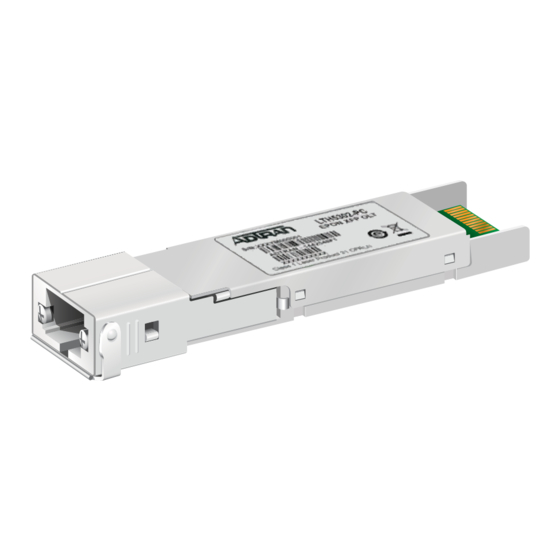
The PR30 Small Form-factor Pluggable (XFP) is a single-
mode fiber XFP that plugs into an ADTRAN optical interface
designed to accept XFPs. The XFP provides a single optical
interface to a physical interface, and is intended for use
with a 10 Gbps Passive Optical Network (PON) Optical Line
Termination (OLT) module. Installed into an appropriate
module, the XFP provides a 10G PON interface to the
supporting system
The XFP OLT Transceiver uses standard 1270 nm/1577
nm optics. The 1270 nm optical burst mode receiver incor-
porates APD/TIA optics for maximum sensitivity. The 10
Gigabit transmitter incorporates a 1577 nm EML DFB laser
assembly.
The following features are supported on this XFP:
■
Data rate: 10 Gbps symmetrical (PR30 denotes
symmetrical high-power budget)
■
Transmit Wavelength: 1577 nm
■
Receive Wavelength: 1270 nm
Optical distance: 20 km maximum
■
■
Hot Pluggable
!
CAUTION
Due to compliance certification requirements, use only XFPs
supplied by ADTRAN. ADTRAN cannot certify system integrity
with other XFPs.
Small Form-factor Pluggable
PR30 10G PON
OLT Transceiver
The following related online documents and resources provide additional information for this
product:
SFP/XFP/SFP+ Compatibility Matrix (online tool, go to: http://www.adtran.com/sfp)
I
NSTALLATION
Before installing the equipment, inspect the XFP. If damage has
occurred during shipping, file a claim with the carrier, and then
contact ADTRAN Customer Support. For more information, refer
to the warranty.
Installation Steps
To install the XFP into an appropriate module, complete the
following steps:
NOTE
Do not remove the protective end cap from the XFP until the fiber
optic cable is ready to be connected.
1. Insert the XFP into the XFP cage on the module. Ensuring
NOTE
The latch on the XFP is for removal only. When removing the
XFP, rotate the latch away from the XFP. It should easily slide out
of the cage.
2. Do not remove the protective end cap until the optical fiber
NOTICE
We recommend that the protective end cap remain on whenever
the transceiver optical fiber connector is not inserted.
3. Continue the installation and turn-up of the host module
S
PECIFICATIONS
Specifications for this XFP are as follows:
■
Optical
♦
♦
♦
♦
that the latch on the XFP is facing upward, slide the XFP all
the way into the XFP cage until there is an audible "click".
connection is made.
using the instructions in the Job Aid provided with the
module or other system-level documentation available
online at www.adtran.com.
Optical transmit level: +2.0 dBm to +5.0 dBm
Optical receive level: –28 dBm to –8 dBm
Optical Connectors: SC/UPC
Compatible with XFP MSA
jobAid
Issue Date: July 2016
Document P/N: 61442548F1-22A
1
Advertisement

Related Manuals for ADTRAN jobAid+ PR30 10G PON


Summary of Contents for ADTRAN jobAid+ PR30 10G PON
- Page 1 The PR30 Small Form-factor Pluggable (XFP) is a single- Do not remove the protective end cap from the XFP until the fiber mode fiber XFP that plugs into an ADTRAN optical interface optic cable is ready to be connected. designed to accept XFPs. The XFP provides a single optical interface to a physical interface, and is intended for use 1.
- Page 2 2. This device must accept any interference received, including interference that may cause undesired operation. WARNING ■ Changes or modifications not expressly approved by ADTRAN could void the user's authority to operate this Read all warnings and cautions before installing or servicing this equipment. equipment. ■...
- Page 3 ADTRAN approuvés dans les produits d'ADTRAN. Pour une Produkte. Eine Liste der ADTRAN zugelassene SFPs und XFPs l i s t e d e s S F P e t X F P A D T R A N a p p r o u v é s , v o i r h t t p : / finden Sie unter http:/www.adtran.com/SFP.
- Page 4 ADTRAN CUSTOMER CARE: Warranty: ADTRAN will replace or repair this product within the warranty period if it does not meet its published specifications or fails while in service. Warranty information can be From within the U.S. 1.888.423.8726 found online at www.adtran.com/warranty.