
Related Manuals for Telex KP-812


Summary of Contents for Telex KP-812
-
Page 1: User Manual
KP-812 Keypanel Desktop with Handset, Desktop, Rack Mount and Lever Key User Manual 9350-7761-000 REV M 6/2005... - Page 2 PROPRIETARY NOTICE The product information and design disclosed herein were originated by and are the property of Telex Communications, Inc. Telex reserves all patent, proprietary design, manufacturing, reproduction, use and sales rights thereto, and to any article disclosed therein, except to the extent rights are expressly granted to others.
-
Page 3: Table Of Contents
GPIO Relay 1 & 2 (A&B) ... 22 Coaxial Connection (CS-200 Coaxial System Interface) ... 22 Replace the Flash Cards to Upgrade the Firmware Version to 2.0 or later ... 23 Cable the CSI-200, KP-812 and Frame ... 23 Chapter 3 ... Basic Operation ... 25 Selecting Headset or Speaker ... - Page 4 Chapter 4 ... Telephone Operation ... 33 Receiving a Phone Call ... 33 Dialing and Hanging Up Using the KP-812 Keypanel Dialing Menu ... 33 Manual Dialing ... 33 Redial ... 34 Autodial ... 34 Chapter 5 ... KP-812 Keypanel Menu System ... 37 Menu System, Menu Access ...
- Page 5 Special Functions ... 56 Chapter 6 ... KP-812 Keypanel Firmware Download ... 57 Download Keypanel Firmware through AZedit ... 57 Chapter 7 ... KP-812 Keypanel Menu System Quick Reference ... 61 Menu Access ... 61 Menu List ... 61 Glossary ... Addendum ...
- Page 6 KP-812 Keypanels User Manual...
-
Page 7: Chapter 1
General Description The RTS ™ KP-812 keypanel fits in a standard 19” rack and is one rack space high. It has 12 keys (one listen button and one talk button make up a key): 10 keys are for intercom talk and listen, two keys are for call waiting response. -
Page 8: Features
• Remote Applications : The KP-812 keypanel can be used in remote applications. The front panel can be mounted separately and connected to the keypanel using up to a maximum of 50 feet of cable. -
Page 9: Connections And Controls
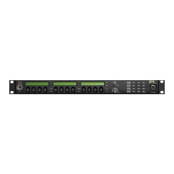
Select MTX IN AUX IN Volume KP812PB-HND Back HEADSET FRAME H-MIC G-MIC FOOT SW/SPEAKER MIC OUT Figure 1. KP-812 Keypanel - Handset Model KP-812 Keypanels User Manual PNL Mic HST Mic Listen Talk Listen Talk Listen Talk Headset 90-240 V AC... -
Page 10: Kp-812 Keypanel - Desktop
KP-812 Keypanel - Desktop Front Back 24 25 Figure 2. KP-812 Keypanel - Desktop Model FRONT Speaker Select / Menu Encoder Volume Control Headset Connector Panel Mic LED Headset Mic LED Panel Mic Connector Speaker LED Headset LED Matrix LED... -
Page 11: Kp-812 Keypanel - Rack Mount
PNL Mic Listen HST Mic Talk 90-240 V AC MIC OUT MIC IN SPK MON Figure 3. KP-812 Keypanel - Rackmount Model FRONT Panel Mic LED Headset Mic LED Panel Mic Connector Listen Keys Panel Display Talk Keys Speaker LED... -
Page 12: Controls Descriptions
It can also be programmed to operate a local GPI output. The Page Up button changes that active page assigned to the main panel. P AND Accepts an electret gooseneck microphone, such as the Telex model MCP-90-XX. ANEL ONNECTOR The model MCP-90 series panel mic connector is a 1/4”... - Page 13 When hands-free is activated, the panel mic is selected and audio is heard through HANDSET ONLY the speaker. RJ-45 ANDSET ONNECTOR (KP-812 K EYPANEL Connects the handset to the KP-812 keypanel so telephone style operation is avail- WITH ANDSET able. ANDSET ECEIVER (KP-812 K EYPANEL WITH The handset, or receiver, allows telephone style operation from the KP-812 keypanel.
-
Page 14: Specifications
+ 8 dBu nominal -40°C (-40°F) to 70°C (158°C) -20°C (-4°F) to 60°C (140°F) 11.3 (W) x 7.623 (D) x3.1 (H) 11.3 (W) x 11 (D) x 3.75 (H) 19 (W) x 7.5 (D) x 1.75 (H) KP-812 Keypanels User Manual... - Page 15 Type: Pin Out: Type: Pin Out: Expansion Connector Type: LCP Connector Type: KP-812 Keypanels User Manual 3-circuit, 1/4” phone jack with threaded metal bushing, compatible with RTS MCP-90 Tip : + Audio and DC bias Ring: Common Sleeve: Chassis ground...
- Page 16 Pin 2 COM contact 3 Pin 3 NO contact 3 Pin 4 NC contact 4 Pin 5 COM contact 4 Pin 6 NO contact 4 Pin 7 +3.3 VDC Pin 8 Ground Pin 9 +3.3 VDC KP-812 Keypanels User Manual...
- Page 17 +3.3 VDC and can source 3 mA for use with an external transistor switch circuit. Headset (External headset connector) Type: Pin-out Note: Mic input -50 dBu nominal. Headset out 0.325 watts into 8 ohms. KP-812 Keypanels User Manual 9-pin male D-Sub Pin 1 3.3 VDC Pin 2 Emitter OC 2 Pin 3...
- Page 18 3-pin XLR Female Pin 1 Ground Pin 2 DC bias and Audio Plus (+) Pin 3 Shield (circuit common) 3-pin XLR Male Pin 1 Shield (circuit common) Pin 2 Audio output + Pin 3 Audio output - KP-812 Keypanels User Manual...
-
Page 19: Chapter 2
“D” check boxes in the Keypanels/Ports setup screen in AZedit. Switch 2: Enable/ Disable the adjustment of listen volumes. Default Setting: Open (Enable) Description: Enables or disables the Key Gain item in the Key Assign menu. Switch 3: Unused Default Setting: Open (Enable) KP-812 Keypanels User Manual Chapter Installation... - Page 20 Switch 6: Reserved Switch 7: Reserved. Must be left in the Open position. Switch 8: Reserved, Must be left in the Open position. Figure 4. KP-812 Keypanel board, DIP switch placement. KP-812 Keypanels User Manual...
-
Page 21: Connections
Connections EXP. and LCP. Connectors Connect from the EXP connector on the back of the KP-812 keypanel to the Expansion 1 connector of an optional EKP-812 Expansion Panel. Use the interconnect cable supplied with the Expansion Panel. Note: JP1 must have pins 1 and 2 shorted to use the LCP connection. -
Page 22: Headset Connector
Provides the ability to link the unit to the matrix using a single 75 ohm coaxial cable. The interface converts all audio and data streams to a single transmission path. Perfect for systems where there are existing, but unused 75 ohm video cable. Requires CSI-200 interface unit at the intercom matrix end. KP-812 Keypanels User Manual... -
Page 23: Replace The Flash Cards To Upgrade The Firmware Version To 2.0 Or Later
Connect the coaxial calbe (up to 1000 ft) to Coax A or Coax B on the CSI-200 (depending upon the channel being used). Connect the opposite end of the coaxial cable to the KP-812 COAX connect on the back of the unit. - Page 24 KP-812 Keypanels User Manual...
-
Page 25: Chapter 3
The minimum volume level for either the keypanel speaker or headset may be adjusted. See, Service Menu, Min Vol . Note: You can save the volume adjustments to be the power-up defaults using Service Menu, Save Cfg . KP-812 Keypanels User Manual Chapter Basic Operation... -
Page 26: Listen Source Selection Led
If the encoder is pushed twice it will go back to the previously selected item in table 1. Handset/Headset Selected Speaker Table Headset/Handset MATRIX IN AUXIN1 The audio being heard on headset is from MATRIX IN. Audio level on headset will be changed through the volume encoder. Table KP-812 Keypanels User Manual... -
Page 27: Intercom Keys And Displays
(Options menu, Intercom Configuration, Options tab). LED Indications for Intercom Keys Note: For the Japanese model KP-812 keypanel, the talk ON LED will appear red and the Listen ON LED will appear green. Talk LED Indications Each button is back lit with a Bi-colorLED as an indicator. The talk LED is the button below the display panel. - Page 28 There is an incoming call from the destination assigned to the key. Activate the key to talk back. Note: The duration of incoming call flash is controlled by DIP switch 4 on the KP-812 keypanels. See Option Switch Settings , for further information.
-
Page 29: Intercom Key Operation
Intercom Key Operation Basic Intercom Key Operation The upper button of an intercom key is on continuously (if assigned). The lower button activates the talk (if assigned). If there is no talk assignment for an intercom key, the talk button will not activate. If there is no listen assignment, the listen button will not activate. -
Page 30: Operation Of Intercom Keys With Options
If an intercom key is assigned to talk to an intercom port that is designated as a TIF port in AZedit, tapping the talk button will activate the KP-812’s dialing menu. See Telephone Operation . Note: You designate an intercom port as a TIF port by checking the Port is TIF check box in AZedit. -
Page 31: Addressing
Turn the encoder knob and scroll to Address X, tap the knob once. Tap on the selected address. The CWW will display Save Config? Tap the encoder knob to save. The displays will show “*******” and change to “ xxxxxx”, where xxx is the address. KP-812 Keypanels User Manual... - Page 32 KP-812 Keypanels User Manual...
-
Page 33: Chapter 4
Options tab). Note, this check box also affects other tally indications. For further information, see the AZedit User Manual. Dialing and Hanging Up Using the KP-812 Keypanel Dialing Menu The dialing menu will only activate when talking to an intercom port that has the “Port is TIF” check box activated in AZedit. -
Page 34: Redial
2. Rotate the encoder knob until AutoDial appears. 3. Tap the encoder knob. 4. Rotate the encoder knob until the desired number to autodial appears. 5. Tap the encoder knob. 6. If the far end answers, begin your conversation. KP-812 Keypanels User Manual... - Page 35 Occasionally you may receive intercom caller namesin the Call Waiting Window while you are talking on the phone. In this case, the dialing menu options will be cleared from the Call Waiting Window, and the Hang Up option will not be available. KP-812 Keypanels User Manual...
- Page 36 KP-812 Keypanels User Manual...
-
Page 37: Chapter 5
A menu system quick reference is located at the back of this manual (page 59). MENU SYSTEM, MENU ACCESS On the front panel of the KP-812 keypanel, turn the encoder knob to scroll to the menu. Tap the encoder to select the menu. -
Page 38: Display Menu, Chan On
If available, the entire alpha can be seen by rotating the encoder knob. Display Menu, Version Displays the firmware version of the keypanel. Note: For Firmware upgrades, contact your intercom system dealer. The KP-812 Keypanel firmware can be upgraded throughout AZedit. See KP-812 Keypanel Download on page 55. KP-812 Keypanels User Manual... -
Page 39: Menu System, Key Assign Menu
4. Tap the encoder once to select a list. In some cases, “Wait” may display while the requested list is uploaded from the intercom system. KP-812 Keypanels User Manual Assign a key to talk/listen to another intercom port. Assign a key to talk/listen to a party line. -
Page 40: Key Assign, Pt-To-Pt
Assigns a key that talks or listens to another intercom port. Note, some pt-to-pt destinations may be non-keypanel devices that cannot activate talk and listen paths. Therefore, if you want full communications, you may need to assign both talk and listen on the key. KP-812 Keypanels User Manual... -
Page 41: Key Assign Menu, Party Line
Quick Assignment is made. The Options are Party Line Point -to-Point Group Special List Also, from this menu, special functions can be individually assigned to a talk/listent assign- ment. For the different special assignments, see page 38. KP-812 Keypanels User Manual... -
Page 42: Key Assign Menu, Reset Vols
Done displays. All key gains are now reset to the default level. Hold the encoder knob for 1 second to exit. Note: You do not need to run Save Cfg after resetting key gains. These settings are stored in the intercom system. KP-812 Keypanels User Manual... -
Page 43: Menus
The chime option will continue on a key even if you change the key assignment. Removing the chime option from a key Repeat the procedure to add chime, but tap any keys where the LEDs are lit red to turn them off. Run Save Cfg to store the changes. KP-812 Keypanels User Manual... -
Page 44: Menu, Key Option, Key Groups
Tap all the keys where the LEDs are lit green. This will turn the LEDs off. Hold the encoder knob for 1 second to exit. The key group is now cleared. Run Service Menu, Save Cfg to store the cleared key group setting. KP-812 Keypanels User Manual... -
Page 45: Menu, Key Option, Solo
Select Exclusive, then tap the encoder knob. Tap the exclusive key to turn off the LEDs. Hold the encoder knob for 1 second to exit. The exclusive key is now cleared. Run Service Menu, Save Cfg to store the Exclusive setting KP-812 Keypanels User Manual... -
Page 46: Service Menu
Turn the encoder knob clockwise to increase the brightness and counterclockwise to reduce the brightness. Note: The brightness scale ranges from 0 to 100, with 100 being the brightest. Run Service Menu, Save Cfg to store the LCD Bright setting. KP-812 Keypanels User Manual... -
Page 47: Service Menu, Dsp Func
Gating displays to indicate that no filtering is selected. Tap the encoder knob. ¡ Gating displays. The arrow incidates that gating is now selected. Hold the encoder knob for 1 second to exit. Run Service Menu, Save Cfg to save the change. KP-812 Keypanels User Manual... - Page 48 Tap the encoder to select if the audio should be activated to the destination. Hold the encoder knob for 1 second to exit the mixing selections. Run Service Menu, Save Cfg to save the change Service Menu, Hdst Sel KP-812 Keypanels User Manual...
-
Page 49: Service Menu, Handset
LCP-16 adjusts keys 17-32, and so forth. If you do not want to use an LCP-16 with certain keys, you must program the KP-812 Key- panel to skip those keys. For example, you may not want to use the LCP-16 with the KP-812 Keypanel but do want to use it with an EKP KP-816. -
Page 50: Service Menu, Local Gpio
GPI Input activates. Hold the encoder knob for second to exit , or tap the encoder knob twice to back up and make more assignments. Run Service Menu, Save Cfg to store local GPIO settings. KP-812 Keypanels User Manual... -
Page 51: Removing An Input Assignment
Tap an intercom button or user assignable key to add or remove the GPI output assignment. Press the encoder knob for 1 second to exit or tap the encoder knob twice to back up and make more assignments. Run Service Menu, Save Cfg to store local GPIO settings. KP-812 Keypanels User Manual... -
Page 52: Service Menu, Matrix Out
This menu item allows the user to set the minimum volume level for both the keypanel speaker and the headset speaker(s). This is the minimum volume level available on the volume control located on the front of the KP-812. Turn the encoder knob until Min Volume displays. Tap the encoder knob. -
Page 53: Service Menu, Speaker
AZedit, appear to be in the wrong position on the keypanel or expansion panel. The KP-812 keypanel and EKP-816 use Module ID numbers (Mod ID Numbers) to define the address of each key and display module. See Figure 7. -
Page 54: Service Menu, Output Level
Sidetone lets you adjust the level of your own voice heard in the headphones when using a headset. Most people prefer some amount of sidetone to overcome the muffled sensation when talking, especially when wearing a full-muff headset. The maximum level is 0dB. KP-812 Keypanels User Manual... -
Page 55: Service Menu, Test Panel
Press the encoder knob for 1 second to exit. Run Service Menu, Save Cfg to store the Tally Duration settings. Note: If DIP switch four is closed the tally lasts for as long as the caller’s talk key is closed. KP-812 Keypanels User Manual... -
Page 56: Special Functions
Turn the encoder knob to scroll to a menu item you wish to assign to the key. The assignment should appear in the Call Waiting Window. Hold the user assignable key until the LED behind the key turns a constant green for two seconds. This verifies the assignments have been made KP-812 Keypanels User Manual... -
Page 57: Chapter 6
You may select more than one port at a time by holding CTRL key down while you select. 4. Right-click the highlighted selections and select Download Firmware. The Firmware Download Window appears. 5. Using the browse feature, browse to the file to be downloaded ( XXX .hex) KP-812 Keypanels User Manual Chapter Download... - Page 58 The firmware download to the master is complete. This may take a few minutes to occur. It will take 10 minutes or more to download to the keypanel. Note: The Keypanel Version Information window shows the progress download. 9. Verify the version upgrade in the Keypanel Version Information Window is correct. KP-812 Keypanels User Manual...
- Page 59 KP-812 Keypanels User Manual...
- Page 60 KP-812 Keypanels User Manual...
-
Page 61: Chapter 7
KP-812 Keypanel Menu System Menu Access On the front panel of the KP-812 keypanel, turn the encoder knob to scroll to the menu. Tap the encoder to select the menu. Turn the encoder knob clockwise to scroll forward, and counterclockwise to scroll backward through a list of menus. - Page 62 KP-812 Keypanels User Manual...
-
Page 63: Glossary
It is also useful to force listening when it is desirable to have an operator continuously hear a party line or other source. KP-812 Keypanels User Manual Glossary... - Page 64 This can help to prevent occasional feeback between the speaker and microphone due to volume settings, microphone placement, etc. For setup and usage, search for “Speaker Dim” in the keypanel manual index. KP-812 Keypanels User Manual...
- Page 65 Once an IFB has been set up and named, it can be assigned to any keypanel key (provided that IFB assignment has not been restricted or dis- abled in the intercom system configuration software). For further information about IFBs, search “IFB” in AZedit user manual. KP-812 Keypanels User Manual...
- Page 66 GPI Input. Intercom ports have identification numbers 001,002, etc. These numbers cannot be changed, but may not be commonly known to intercom system users. Each intercom port also has a default name, called an “alpha”, because this KP-812 Keypanels User Manual...
- Page 67 2 talk key assignment in a stacked talk key ar- rangement to both send audio and key a device, such as a paging amplifier or a 2- way radio. KP-812 Keypanels User Manual...
- Page 68 A special device, called a Trunking Master Controller, is required to control access and usage for the trunked intercom ports. A configuration utility, called CSTrunk, is used to set up the Trunking Master Controller. KP-812 Keypanels User Manual...
- Page 69 KP-812 Keypanels User Manual...
-
Page 71: Addendum
RVON 1 RTS Voice Over Network Interface Card for the KP-32 and KP-812 Family of Keypanels ADDENDUM... - Page 72 RVON-1 User Manual...
- Page 73 Proprietary Notice The RTS product information and design disclosed herein were originated by and are the property of Telex Commu- nications, Inc. Telex reserves all patent, proprietary design, manufacturing, reproduction, use and sales rights thereto, and to any article disclosed therein, except to the extent rights are expressly granted to others.
- Page 74 RVON-1 User Manual...
- Page 75 RVON-1 Relay ...11 Addresses and the RVON-1...11 Configure the RVON-1 from the KP-32 ...12 Configure the RVON-1 from the KP-812 ...14 Configure the RVON-8 using AZedit to contact the RVON-1 ...16 Download RVON-1 Firmware Through AZedit ...17 Appendix A ...19...
- Page 76 This Page Intentionally left blank. RVON-1 User Manual...
-
Page 77: General Description Of The Rvon-1 Voice Over Network Card
The RVON-1 is compatible with any RTS™ Matrix Intercom system equipped with a suitable RVON interface. In conjunction with any new or existing KP-32 or KP-812 keypanel, the RVON-1 brings a new level of enterprise-wide and remote access functionality to your RTS™ Matrix Intercom. -
Page 78: Specifications
Specifications Digital Compression Audio Bit Rate G.711 G.729AB G.723 5.3k/6.3k * Data depends on CODEC selection Note: The Playout Delay and Bandwidth depend on the configured amount of audio per packet. Connections - RJ-45 Ethernet via backcard - 14-pin KP Compatible Expansion Connector Pin 1 ... -
Page 79: Flash Chip Replacement
Firmware Compatibility Requirements for the RVON-1 Card l l o l l o Table 1. Compatibility Requirements for the RVON-1 Card Flash Chip Replacement The KP32, KP-32J , KP-632, and KP-832 must upgraded to 4MB flash chips that are programmed in the factory. -
Page 80: Installation Of The Rvon-1 Card (Cont.)
Figure 3. The placement of the spacer and screw position on the RVON-1 card for KP-32 series keypanels. Figure 4. The placement of the spacer and screw position on the RVON-1 card for the KP-812 series keypanels. RVON-1 User Manual... -
Page 81: Rvon-1 Relay
Figure 6. The J4 connector on the KP-32 board. In the KP-812, the RVON-1 card connects to the KP-812 by way of the J2 connector on the RVON-1 attached to J37 on the KP-812 header. Gently secure the board in place. See Figure 7. -
Page 82: Addresses And The Rvon-1
Addresses and the RVON-1 Because the RVON-1 has an Ethernet interface, it is required to have a MAC (Media Access Control) address. This is a low level address that contains 48 bits. Do not confuse this address with an IP (Internet Protocol) address. - Page 83 NOTE: Press PGM to skip over any octet that does not need modifications. Repeat steps 13 and 14 until the entire Netmask is entered. Press PGM. The Gateway IP Address menu item appears. NOTE: Once you have entered the Netmask, you may need to enter the Gateway IP Address. A Gateway is a node (for example, a computer) on a network that serves as an entrance to another network.
- Page 84 Configure the RVON-1 from the KP-812 TOP LEVEL MENU, SERVICE, RVON SETUP Set the IP Address from the Service Level Menu The RVON-1 card, when shipped has a default IP Address already configured. This must be changed in order for the RVON-1 card to function properly because the pre-configured IP Address may not work with your network.
- Page 85 To select the connection offer, do the following: On the KP-812, scroll to RVON Conn., then tap the encoder knob. The currently selected connection offer appears in the CWW window. If you have not previously selected the connection, you will see “none”.
-
Page 86: Configure The Rvon-8 Using Azedit To Contact The Rvon-1
Configure the RVON-8 using AZedit to contact the RVON-1 To configure the RVON-1 card, do the following: From the Status menu, select I/O Cards. The I/O Card Status screen appears showing the types of installed cards . Right click on an RVON-8 card and select RVON-8 Configuration. The RVON-8 Configuration screen appears . -
Page 87: Download Rvon-1 Firmware Through Azedit
From the Device Channel drop down list, select Channel 1. There may be two channels listed, but the connection can only be made through channel 1. From the CODEC Type drop down list, select the CODEC type. From the Packet Size drop down list, select the size of each audio packet. NOTE: A CODEC is an algorithm used to compress audio. - Page 88 Using the Browse feature, browse to the file to be downloaded. Click Open. The Download Device Firmware screen appears. Click Begin Download. The download begins. Click OK. The RVON-1 firmware download is complete. This takes a minute or two to occur. WARNING! - Do NOT power down the keypanel until you have verified the new version information from AZedit.
- Page 89 Appendix A Basic Network Configuration This section covers basic network configuration set up and testing. Also covered are basic concepts and operations, including the difference between LAN and WAN networks and how IP Addressing is used. In a networked environment, such as a company, typically there are many computers connected together using a router or a switch (for more information router or switch in the definitions section).
- Page 90 A wide area network connects two or more LANs and can span a relatively large geographical area. For example, Telex Headquarters in Burnsville, MN is connected to several branch offices in Nebraska and Arkansas over the wide area network. The largest WAN in existence is the Internet.
- Page 91 IP address for the URL you are requesting (http:// www.telex.com). To obtain this address, the computer contact a DNS server (Domain Name Server). Once the IP address is found, it tries to connect to the http port of the network device (port 80). See Table 1 for a list of the more well-known port numbers.
- Page 92 Table 3. Well-Known TCP Port Numbers i t l i l p l i a l a i e l i e l i l i a l l e - t f e i l RVON-1 User Manual...
- Page 93 IP Addresses If you do not know your IP Address, you can open a DOS screen in Windows up the ipconfig screen. To find your IP Address using ipconfig, do the following: From the Start Menu, open a Command Prompt window. At the prompt, type ipconfig, then press Enter.
- Page 94 Ping a Computer Pinging a computer on the network makes sure it is able to be “seen” and receive messages on the network. Note: You can also ping your RVON-8 card to verify that it is responding over the network by putting the cards IP address in place of the computer IP address.
- Page 95 Possible Pitfall with Routers, Gateways, and Switches Anytime computers communicate through routers, gateways, and switches, they may be allowed or denied the connection. Network interface devices can be configured to block specific outgoing requests, as well as incoming requests, based on the IP address and/or port. This is one of the security mechanisms of a router. This also happens when broadcast messages are sent and received.
- Page 96 RVON-1 Specific Configuration RVON-1 cards use ports for communication of audio and control packets. Because routers can be configured to block certain incoming and outgoing requests, you will need to open the following ports in your network to allow WAN connections to and from a Network Interface Device. See Table 4 for the ports that need to be opened for the RVON-1 card to operate properly.
- Page 97 - A DNS Server is an Internet service that translates domain names (for example, in the URL http://www.telex.com, the domain name is telex.com) into IP Addresses. The Internet is based on IP Addresses which are numeric and since domain names are alphabetic, they are easier to remember.
- Page 98 A wide area network connects two or more LANs and can span a relatively large geographi- cal area. For example, Telex Headquarters in Burnsville, MN is connected to several of its branch offices in Nebraska and Arkansas over the wide area network. The largest WAN in existence is the Internet.
- Page 99 TELNET. To set the IP Address, use the keypanel display menu, see pages 10 - 14. Without access to the physical KP-32 or KP-812 where the RVON-1 is installed, you can still configure the card through the use of Telnet. The following instructions will show you how to access the Telnet screens and show you some of the information you can display and edit.
- Page 100 3. Press Enter. The RVON login screen appears. In the logon field, type the RVON login (default = Telex). Press Enter. In the password field, type the RVON password (default = password). Press Enter. A prompt appears. Type dbgcmd to access the debug command screens.
- Page 101 2. Set the destination channel type to RVON-1. At the command prompt type: set chan dest_type 0 3. Set the RVON user to Telex At the command prompt type: set rvon user Telex RVON-1 User Manual " t " x p "...
- Page 102 e l i t t i Codec: Determines how the audio is compressed/decompressed and the name given to the defined algorithm. Codec Rate: Actual bits per second of the audio in compressed form. This is sent over the network through various data packets.
- Page 103 All are “set channel #” commands because they are for each audio channel. Typing, “sys_printenv” from the “MXP” Debug system prompt shows these settings. RVON-1 User Manual c i t / I - e l i...
- Page 104 A selectable RS232/485 serial port is at connector J1. Jumper connections on J10, J11, and J12 select the signal mode on J1. • When J10, J11, and J12 are jumped from pins 1 to 2 - J1 is configured for RS485. •...
- Page 105 RVON-1 User Manual...