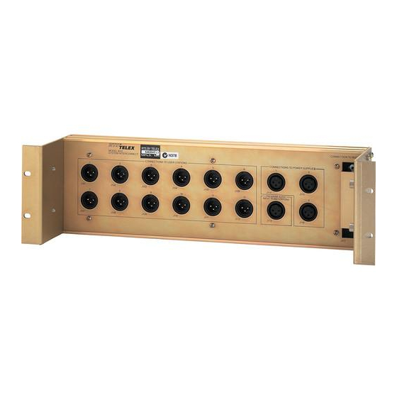
Summary of Contents for Telex 4012
- Page 1 DRAWINGS MANUAL System Interconnect Assembly Drawing No. AS4594 S D4.594 AS4687 ILL4687 BD4878 Rev A 9300-4687-000 5/93 MODEL 401 2 LIST OF DRAWINGS Title Circuit Board Component Layout Schematic Diagram Final Assembly Illustration Drawing Block Diagram...
- Page 2 MODEL 4012 PARTS LIST Final Assembly Parts Llst. Assembly No. 9010-4687-00 (Reference Drawing AS4687 for REF numbers) REF NO. Circuit Board Assembly Parts List, Assembly No. 9030-4594-00 (Ref Drawing SD4594 for REF numbers) REF NO. J101 J112 J113 J116 J117...
- Page 3 PL 9030-4594-00. RTS SYSTEMS BURBANK, CALIFORNIA DATE ASSEMBLY , P.C.B. , 11-21-88 4012 S P L I T ~ E R SIZE FSCY AS 4594 c ( 6 0 5 7 2 l T ocAu 1 OF 1 l ~ c e ~...
- Page 6 CONNECTOR F E M A L E...


