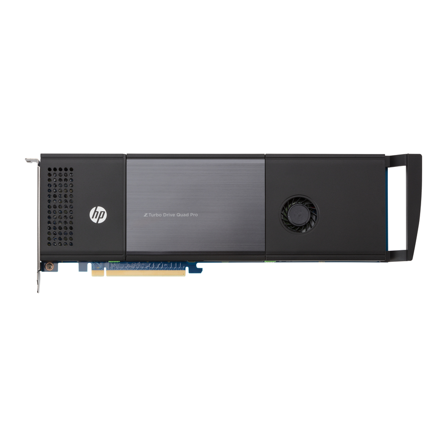
HP Z Turbo Drive Quad Pro - SSD Module Manual
- Installation manual (18 pages)
Advertisement
- 1 Kit contents
- 2 Before you begin
- 3 Installing additional M.2 modules in the HP Z Turbo Drive Quad Pro
- 4 Accessing the internal components of the computer
- 5 Installing the drive in an HP Z440 Workstation
- 6 Installing the drive in an HP Z640 Workstation
- 7 Installing the drive in an HP Z840 Workstation
- 8 Installing multiple HP Z Turbo Drives or HP Z Turbo Quad Pro Drives
- 9 Completing the installation
- 10 Configuring the computer
- 11 Warnings and cautions
- 12 Documents / Resources
Kit contents
- HP Z Turbo Drive Quad Pro
- LED cable
- Installation instructions
- Warranty information
Before you begin
To view QuickSpecs and determine the compatibility of this product with your HP computer, see http://www.hp.com/go/productbulletin.
The minimum BIOS revision for the HP Z440, Z640, and Z840 Workstations is 1.62. If these requirements are not met, the computer does not recognize the drive.
If you are installing an operating system image on the drive, remove all other storage devices. Install this drive in the primary PCIe slot indicated for your workstation and install the operating system image before installing additional HP Z Turbo Drives or HP Z Turbo Drive Quad Pros or reinstalling the other storage devices. The preferred slots are noted in the installation instructions for each computer. If you will be using the drive as a data drive, you do not need to remove the other storage devices.
Installing additional M.2 modules in the HP Z Turbo Drive Quad Pro
You can install up to four M.2 PCIe SSD modules in this drive. Load the modules from the cover hinge to the PCIe edge connector in the following order.
TIP: Install all M.2 modules before installing the HP Z Turbo Drive Quad Pro assembly.

- Open the drive cover.

- Slide the latch to the left of the door to the left until the red area beneath the latch is fully exposed (1).
- Slide the right latch to the right and hold it (2).
- While holding the right latch, press the center of the edge of the cover and lift it (3).
- Loosen the two captive screws on the heat sink (1)

- Lift the heat sink to expose the M.2 modules (2).
NOTE: The drive comes with at least two M.2 modules preinstalled. - Remove the standoff from the next M.2 slot.

- Insert standoff into the curve of the right edge of the M.2 module.

- Slide the M.2 module into the connector (1) and then press down until the standoff is aligned with the embedded nut (2).

- Screw the standoff into the nut.

- Reinstall the heat sink (1) and tighten the captive screws (2).
Be sure that the tabs on the heat sink are under the metal pins and can rotate.

- Close the cover (1) and slide the left latch to the right until no red is showing (2).


Accessing the internal components of the computer
- If you need help preparing the computer for this installation, consult the removal and replacement procedures in the HP Customer Self Repair Services Media Library at http://www.hp.com/go/sml or in the service guide for your computer at http://www.hp.com/support/manuals.
- Power down the workstation, and then disconnect the power cord.
- Power down all external devices, and then disconnect them from the workstation.
- Remove the access panel by lifting up on the release latch and raising the panel from the chassis.
Installing the drive in an HP Z440 Workstation
If more than one of any of the following drives are to be installed in a system, a unique address for each drive must be configured before installation:
- HP Z Turbo Drive
- HP Z Turbo Drive G2
- HP Z Turbo Quad Pro
For configuration instructions, see Installing multiple HP Z Turbo Drives or HP Z Turbo Quad Pro Drives.
- Press down on the two green PCI retention clips (1) located inside the workstation until they release, and then rotate them down to raise the retention clamp (2).

- Raise the slot cover (1) and rotate it toward the inside of the chassis (2) to access PCIe slot 5.

- Align the connectors on the PCIe drive with the socket on the system board and install the drive into the socket.

- Connect the LED cable to the HDD activity header on the PCIe drive that is marked HDDACT_OUT. Then, connect the other end of the LED cable to the HDD LED connector on the system board.
NOTE: To locate the HDD LED connector on the system board, see the System Board Overview on the service panel. - Press the two green PCI retention clamp tabs on the rear of the chassis up until they lock into place.


Installing the drive in an HP Z640 Workstation
If more than one of any of the following drives are to be installed in a system, a unique address for each drive must be configured before installation:
- HP Z Turbo Drive
- HP Z Turbo Drive G2
- HP Z Turbo Quad Pro
For configuration instructions, see Installing multiple HP Z Turbo Drives or HP Z Turbo Quad Pro Drives.
- Press down on the two green PCI retention clips located on the rear of the chassis (1) until they release, then rotate the clips down to raise the retention clamp from the slot covers (2).

- Raise the slot cover (1) and rotate it (2) toward the inside of the chassis to access PCIe slot 5.

- Align the connectors on the PCIe drive with the socket on the system board and install the drive into the socket.

- Connect the LED cable to the HDD activity header on the PCIe drive that is marked HDDACT_OUT. Then, connect the other end of the LED cable to the HDD LED connector on the system board.
NOTE: To locate the HDD LED connector on the system board, see the System Board Overview on the service panel. - Press the two green PCI retention clamp tabs on the rear of the chassis up until they lock into place.


Installing the drive in an HP Z840 Workstation
If more than one of any of the following drives are to be installed in a system, a unique address for each drive must be configured before installation:
- HP Z Turbo Drive
- HP Z Turbo Drive G2
- HP Z Turbo Quad Pro
For configuration instructions, see Installing multiple HP Z Turbo Drives or HP Z Turbo Quad Pro Drives.
- Squeeze the two green tabs together to release the retainer (1), rotate the PCI retainer (2) up, and lift it out of the chassis (3).

- Lift the green lever to rotate the retention bracket (1) out of the way, raise the slot cover (2), and then rotate the slot cover toward the inside of the chassis (3) to access either PCIe slot 6, or slot 4.

- Align the connectors on the PCIe drive with the socket on the system board and install the drive into the socket, then lower the retention bracket into place.
NOTE: If the computer has one CPU installed, the drive may be used only in PCIe slot 6. If the computer has a second CPU installed, the drive may also be used in slot 4.

- Connect the LED cable to the HDD activity header on the PCIe drive that is marked HDDACT_OUT. Then, connect the other end of the LED cable to the HDD LED connector on the system board.
NOTE: To locate the HDD LED connector on the system board, see the System Board Overview on the service panel. - Insert the hooks on the back end of the PCI retainer into the slots on the back of the chassis (1) and lock the retainer in place by rotating it down into position (2).
NOTE: The PCI retainer locks the PCI retention clamp in place.


Installing multiple HP Z Turbo Drives or HP Z Turbo Quad Pro Drives
Configuring the drive addresses
If more than one of any of the following drives are to be installed in a system, a unique address for each drive must be configured before installation:
- HP Z Turbo Drive
- HP Z Turbo Drive G2
- HP Z Turbo Quad Pro
NOTE: A second HP Z Turbo Quad Pro can be installed on an HP Z840 with a second CPU only.
The HP Z Turbo Drive and HP Z Turbo Drive G2 both support a single M.2 module and have jumpers that can be set to eight unique addresses. Each HP Z Turbo Drive and HP Z Turbo Drive G2 must have a unique address. For possible jumper configurations and corresponding labels, see the following diagram.

The HP Z Turbo Drive Quad Pro has switches that can be set to four unique addresses. Each HP Z Turbo Drive Quad Pro must have a unique address. For possible switch configurations and corresponding labels, see the following diagram.
TIP: The black rectangle indicates the switch position.

Some of the HP Z Turbo Drive Quad Pro and HP Z Turbo Drive solutions addresses overlap. To prevent configuration of identical addresses, see the following chart.
NOTE: HP recommends setting the addresses of any HP Z Turbo Drive Quad Pros, and then setting the addresses of any HP Z Turbo Drive solutions. If using a combination of solutions, HP recommends using Address C or Address D for the HP Z Turbo Drive Quad Pro and Address 0, Address 1, Address 2, or Address 3 for the HP Z Turbo Drive solution.
| HP Z Turbo Drive and HP Z Turbo Drive G2 address | HP Z Turbo Drive Quad Pro address | Instructions |
| 0 | A | If an HP Z Turbo Drive Quad Pro is configured at Address A, the HP Z Turbo Drive solutions must not be at either Address 0 or Address 1. |
| 1 | ||
| 2 | B | If an HP Z Turbo Drive Quad Pro is configured at Address B, the HP Z Turbo Drive solutions must not be at either Address 2 or Address 3. |
| 3 | ||
| 4 | C | If an HP Z Turbo Drive Quad Pro is configured at Address C, the HP Z Turbo Drive solutions must not be at either Address 4 or Address 5. |
| 5 | ||
| 6 | D | If an HP Z Turbo Drive Quad Pro is configured at Address D, the HP Z Turbo Drive solutions must not be at either Address 6 or Address 7. |
| 7 |
Configuring the LED cables
If more than one of any of the following drives are to be installed in a system, you must configure the LED cables between the drives and the system board as follows.
To configure the LED cables on a system with two HP Z Turbo Drive Quad Pros:
- Connect an LED cable to the HDD activity header on the first PCI drive that is marked HDDACT_OUT.
- Connect the other end of this LED cable to the HDD activity header on the second PCI drive that is marked HDDACT_IN.
- Connect an LED cable to the HDD activity header on the second PCI drive that is marked HDDACT_OUT.
- Then, connect the other end of this LED cable to the HDD LED connector on the system board.
NOTE: To locate the HDD LED connector on the system board, see the System Board Overview on the service panel.
To configure the LED cables on a system with an HP Z Turbo Drive Quad Pro and an HP Z Turbo Drive:
- Connect an LED cable to the HDD activity header on the HP Z Turbo Drive that is marked HDDACT1.
- Connect the other end of this LED cable to the HDD activity header on the HP Z Turbo Drive Quad Pro that is marked HDDACT_IN.
- Connect an LED cable to the HDD activity header on the HP Z Turbo Drive Quad Pro that is marked HDDACT_OUT.
- Then, connect the other end of this LED cable to the HDD LED connector on the system board.
NOTE: To locate the HDD LED connector on the system board, see the System Board Overview on the service panel.
Completing the installation
- Reinstall the access panel.
- Reconnect the AC power cord and turn on the workstation.
Configuring the computer
The HP Z Turbo Drive Quad Pro is an NVMe device. NVMe devices require a driver for proper detection and operation. Windows® 8 and higher have this driver by default. To download the driver for Windows 7, go to http://www.hp.com/go/workstationsupport.
For Linux®, an NVMe driver was merged into version 3.3 of the Linux kernel.
When powering up the computer after installation, a new hard drive identifies itself as uninitialized storage. See the operating system documentation for information about how to set up the new drive.
Warnings and cautions

Any surface or area of the equipment marked with this symbol indicates the presence of a hot surface or hot component. If this surface is contacted, the potential for injury exists. To reduce the risk of injury from a hot component, enable the surface to cool before touching.

Any surface or area of the equipment marked with this symbol indicates the presence of an electrical shock hazard. To reduce the risk of injury from electrical shock, do not open any enclosed area marked with this symbol.
To reduce the risk of electric shock or damage to your equipment:
- Do not disable the power cord grounding plug. The grounding plug is an important safety feature.
- Plug the power cord in a grounded (earthed) outlet that is easily accessible at all times.
- Disconnect power from the equipment by unplugging the power cord from the electrical outlet.

To reduce the risk of serious injury, read the Safety & Comfort Guide. It describes proper computer setup, posture, health, and work habits for computer users, and provides important electrical and mechanical safety information. This guide is located at http://www.hp.com/ergo and on the documentation CD (if one is included with the product).
If a product is shipped in packaging marked with this symbol  , the product must always be lifted by two persons to avoid personal injury due to product weight.

Static electricity can damage the electronic components of the computer. Before beginning these procedures, be sure you discharge static electricity by briefly touching a grounded metal object.
To prevent damage to the computer, observe the following Electrostatic Discharge (ESD) precautions while performing the system parts removal and replacement procedures:
- Work on a static-free mat.
- Wear a static strap to ensure that any accumulated electrostatic charge is discharged from your body to the ground.
- Create a common ground for the equipment you are working on by connecting the static-free mat, static strap, and peripheral units to that piece of equipment.
NOTE: HP accessories are for use in HP computer products. They have been extensively tested for reliability and are manufactured to high quality standards.

If you are installing an operating system image on the drive, remove all other storage devices. Verify that you installed this drive in the primary PCIe slot indicated for your workstation, and then install the operating system image before installing a second drive of the same type or reinstalling the other storage devices. The preferred slots are noted in the installation instructions for each computer. If you are using the drive as a data drive, you do not need to remove the other storage devices.
NOTE: Some operating systems automatically schedule defragmenting sessions. This offers no benefit for an SSD; therefore, the user can remove the automatic scheduling. This will also save energy.

Documents / Resources
References
Download manual
Here you can download full pdf version of manual, it may contain additional safety instructions, warranty information, FCC rules, etc.
Advertisement
Thank you! Your question has been received!


Need Assistance?
Do you have a question about the Z Turbo Drive Quad Pro that isn't answered in the manual? Leave your question here.