Table of Contents
Advertisement
Available languages
Available languages
Quick Links
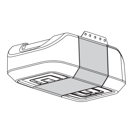
PREMIUM Series
DC Chain Drive Garage
Door Opener with
Battery Backup
Model 8360
FOR RESIDENTIAL USE ONLY
■ Please read this manual and the enclosed safety materials carefully!
■ Fasten the manual near the garage door after installation.
■ The door WILL NOT CLOSE unless the Protector System
aligned.
■ Periodic checks of the garage door opener are required to ensure safe operation.
■ The model number label is located on the front panel of your garage door opener.
■ This garage door opener is ONLY compatible with MyQ
accessories.
■ ONLY enable the Timer-to-Close* or MyQ
the garage door opener is installed on a sectional door. (*Not available on all
models)
NOTE: If you are installing the garage door opener on a one-piece door, visit
www.liftmaster.com for installation instructions.
.
®
is connected and properly
®
and Security✚ 2.0™
®
remote operation feature* when
Write down the following information for
future reference:
Serial Number:
Date of Purchase:
CONTENTS
Preparation . . . . . . . . . . . . . . . .2-3
Assembly . . . . . . . . . . . . . . . . .4-5
Installation . . . . . . . . . . . . . . . 6-13
Install the Door Control . . . . . . 14-16
®
. . 17-20
Power. . . . . . . . . . . . . . . . . . 21-22
Adjustments . . . . . . . . . . . . . 23-25
Battery Backup*. . . . . . . . . . . 26-27
Operation . . . . . . . . . . . . . . . . . 28
Features . . . . . . . . . . . . . . . . . . 29
Door Control . . . . . . . . . . . . . 30-31
Remote Control . . . . . . . . . . . 32-33
To Erase the Memory . . . . . . . . . 33
To Open the Door Manually . . . . . 34
Maintenance . . . . . . . . . . . . . . . 34
Troubleshooting. . . . . . . . . . . 35-36
Accessories. . . . . . . . . . . . . . . . 37
Warranty. . . . . . . . . . . . . . . . . . 38
Repair Parts . . . . . . . . . . . . . 39-40
* If applicable
www.liftmaster.com
The Chamberlain Group, Inc.
845 Larch Avenue
Elmhurst, Illinois 60126-1196
Advertisement
Chapters
Table of Contents

Related Manuals for Chamberlain LiftMaster PREMIUM Series


Summary of Contents for Chamberlain LiftMaster PREMIUM Series
-
Page 1: Table Of Contents
NOTE: If you are installing the garage door opener on a one-piece door, visit www.liftmaster.com for installation instructions. Write down the following information for future reference: Serial Number: www.liftmaster.com The Chamberlain Group, Inc. Date of Purchase: 845 Larch Avenue Elmhurst, Illinois 60126-1196... -
Page 2: Preparation
Preparation Safety Symbol and Signal Tools Needed Check the Door Word Review 1. Disable locks and remove any ropes This garage door opener has been designed and To prevent possible SERIOUS INJURY or connected to the garage door. tested to offer safe service provided it is installed, DEATH: 2. - Page 3 Preparation Overview/Carton Inventory SECURITY✚ 2.0 ACCESSORIES NOTE: Accessories will vary depending on the garage door opener model purchased. Depending on your specific model, other accessories 886LM may be included with your garage door opener. The instructions for these accessories will be attached to the accessory and are not included Premium Motion-Detecting in this manual.
-
Page 4: Assembly
Assembly Attach the rail to the garage door opener NOTE: ONLY use the bolts removed from the garage door opener. Place the garage door Washered Bolt 5/16"-18x1/2" opener on the packing material to prevent To avoid possible SERIOUS INJURY to finger from scratching. - Page 5 Assembly Tighten the Chain Loosen the inner nut and lock washer on the trolley threaded shaft. Tighten the outer nut until the chain is a 1/2 inch above the base of the rail at the midpoint of the rail. 1/2" Re-tighten the inner nut.
- Page 6 Installation IMPORTANT INSTALLATION INSTRUCTIONS WARNING To reduce the risk of SEVERE INJURY or DEATH: 9. Install wall-mounted garage door control: 1. READ AND FOLLOW ALL INSTALLATION WARNINGS AND INSTRUCTIONS. 2. Install garage door opener ONLY on properly balanced and lubricated garage door. An •...
- Page 7 Determine the header bracket location NOTE: If you are installing the garage door opener on a one-piece door, visit www.liftmaster.com for OPTIONAL Unfinished installation instructions. CEILING Ceiling MOUNT FOR Close the door and mark the inside vertical centerline of the garage door. HEADER Header Wall To prevent possible SERIOUS INJURY or...
- Page 8 Installation 2 Install the Header Bracket You can attach the header bracket either to the OPTION A WALL INSTALLATION (Header Wall) wall above the garage door, or to the ceiling. Vertical 2.1A Centerline of Center the bracket on the vertical Follow the instructions which will work best for Wall Mount Garage Door...
- Page 9 Attach the rail to the header bracket HARDWARE Align the rail with the header bracket. Ring Fastener Insert the clevis pin through the holes in the header bracket and rail. Secure with the ring fastener. Clevis Pin 5/16" X 2-3/4" NOTE: Use the packing material as a protective base for the garage door opener.
- Page 10 Installation Hang the garage door opener FIGURE 2 FIGURE 1 Hanging your garage door opener will vary depending on your Unfinished Ceiling Finished Ceiling garage. Two representative installations are shown. Yours may be different. Hanging brackets should be angled (Figure 1) to Not Provided provide rigid support.
- Page 11 Install the light bulbs Pull on the top center of the light lens and rotate the light lens down. Insert an A19 incandescent (100W maximum) or To prevent possible OVERHEATING of the end panel or light socket: compact fluorescent (26W, 100W equivalent) light •...
-
Page 12: Installation
Installation FIGURE 1 Install the door bracket A horizontal and vertical reinforcement is needed for lightweight garage doors (fi berglass, aluminum, steel, doors with glass panel, etc.) (not provided). A horizontal reinforcement brace should be long enough to be secured to two or three vertical supports. - Page 13 9 Connect the door arm to the trolley IMPORTANT: The groove on the straight door arm MUST face away from the curved door arm. Attach the straight door arm to the outer Close the door. Disconnect the trolley by Attach the curved door arm to the door CORRECT trolley using the clevis pin.
-
Page 14: Install The Door Control
Install the Door Control Install the door control INTRODUCTION HARDWARE ® Compatible with MyQ and Security+ 2.0™ accessories, see page 37. Your garage door Screw To prevent possible SERIOUS INJURY or DEATH from electrocution: opener is compatible with up to 2 Smart Control 6ABx1"... - Page 15 Install the Door Control Position the bottom hole of the door Lift the push bar up and mark the top hole. Remove the door control from the wall Position the bottom hole of the control over the screw and slide and drill a 5/32 inch (4 mm) hole for door control over the screw and down into place.
- Page 16 Install the Door Control Attach the warning labels Attach the entrapment warning label on the wall near the door control with tacks or staples. Attach the manual release/safety reverse test label in a visible location on the inside of the garage door.
-
Page 17: Install The Protector System
® Install the Protector System Introduction IMPORTANT INFORMATION ABOUT THE SAFETY REVERSING SENSORS The safety reversing sensors must be connected and aligned correctly before the garage door opener will move in the down direction. The sending sensor (with an amber LED) transmits an invisible light beam to the receiving sensor (with a green LED). If an obstruction breaks the light beam while the door is closing, the door will stop and reverse to the full open position, and the garage door opener lights will flash 10 times. - Page 18 ® Install the Protector System Install the Safety Reversing Sensors The safety reversing sensors can be attached to the door track, the wall, or the floor. If the door track will not support the sensor bracket a wall installation is recommended. Choose one of the following installations. OPTION A DOOR TRACK INSTALLATION HARDWARE...
- Page 19 ® Install the Protector System 1 Install the Safety Reversing Sensors OPTION C FLOOR INSTALLATION Use an extension bracket (not provided) or wood block to raise the sensor bracket if needed. 1.1C Carefully measure the position of both 1.3C 1.4C Slide the carriage bolt into the slot on Insert the bolt through the hole in the sensor 1.2C...
- Page 20 ® Install the Protector System OPTION B PRE-WIRED INSTALLATION 2.1B 2.2B 2.3B Cut the end of the safety Separate the safety reversing sensor wires and strip 7/16 inch (11 mm) of Connect the pre-installed wires to the sensor wires with wire nuts reversing sensor wire, making insulation from each end.
-
Page 21: Power
Power To avoid installation difficulties, do not activate the garage door opener at this time. 1 Connect Power To reduce the risk of electric shock, your garage door opener has a grounding type plug with a third grounding pin. This plug will only fit into a grounding type outlet. - Page 22 Power Ensure the Safety Reversing Sensors are aligned The door will not close if the sensors Check to make sure the LEDs in both sensors are glowing steadily. The LEDs in both sensors will glow steadily if they have not been installed and aligned are aligned and wired correctly.
-
Page 23: Adjustments
Adjustments INTRODUCTION Your garage door opener is designed with electronic controls to make setup and adjustments easy. The adjustments allow you Without a properly installed safety reversal to program where the door will stop in the system, persons (particularly small children) open (UP) and close (DOWN) position. - Page 24 Adjustments Program the Travel Without a properly installed safety reversal system, persons (particularly small children) could be SERIOUSLY INJURED or KILLED by a closing garage door. • Incorrect adjustment of garage door travel limits will interfere with proper operation of safety reversal system. •...
- Page 25 Adjustments Test the Safety Reversal System With the door fully open, place a 1-1/2 Press the remote control push button to If the door stops and does not reverse on inch (3.8 cm) board (or a 2x4 laid flat) on close the door.
-
Page 26: Battery Backup
Battery Backup* Install the battery Unplug the garage door opener. To reduce the risk of FIRE or INJURY to persons: Open the light lens on the right side panel of the garage door opener. Use a Phillips • Disconnect ALL electric and battery power head screwdriver to remove the battery cover on the garage door opener. - Page 27 Battery Backup* Charge the Battery Battery Status LED NOTE: The Battery Status LED is most visible with the garage door opener light off. Battery does not GREEN LED: have to be fully charged to operate the garage The battery charges when the garage door opener All systems are normal.
-
Page 28: Operation
Operation IMPORTANT SAFETY INSTRUCTIONS WARNING To reduce the risk of SEVERE INJURY or DEATH: 1. READ AND FOLLOW ALL WARNINGS AND INSTRUCTIONS. 10. Safety reversal system MUST be tested every month. Garage door MUST reverse on 2. ALWAYS keep remote controls out of reach of children. NEVER permit children to operate or contact with 1-1/2"... -
Page 29: Features
Features Your garage door opener is equipped with features to provide you with greater control over your ENERGY CONSERVATION garage door operation. For energy efficiency the garage door opener will enter sleep mode when the door is fully closed. The Alert2Close sleep mode shuts the garage door opener down until activated. -
Page 30: Door Control
Door Control USING THE DOOR CONTROL The following features are accessible by lifting up the push bar: LEARN A DEVICE SYNCHRONIZE THE DOOR CONTROL ® Any compatible remote controls, wireless keyless entry, or MyQ accessories can be programmed to To synchronize the door control to the garage door opener, press the push bar until the garage door the garage door opener by pressing the LEARN button on the Motion Detecting Control Panel, see opener activates (it may take up to 3 presses). - Page 31 Door Control Control Panel Setup LIGHT LOCK MOTION SENSOR To change the amount of time the garage door opener lights will stay on: (Premium Motion-Detecting Control NOTE: Your remote controls will NOT work Press and hold the LOCK button until the garage door opener lights flash.* The time interval is when LOCK mode is active however your Panel) indicated by the number of flashes.
-
Page 32: Remote Control
Remote Control Your remote control has been programmed at the factory to operate with your garage door opener. Older LiftMaster remote controls are NOT compatible, see page 37 for compatible accessories. Programming can be done through the door control or the learn button the garage door opener. To program ®... -
Page 33: To Erase The Memory
Remote Control To Erase the Memory ERASE ALL REMOTE CONTROLS AND KEYLESS ENTRIES Press and hold the learn button on garage door opener until the learn LED goes out (approximately 6 seconds). All remote control and keyless entry codes are now erased. Reprogram any accessory you wish to use. -
Page 34: To Open The Door Manually
To Open the Door Manually DISCONNECT THE TROLLEY The door should be fully closed if possible. Pull down on the emergency release handle. To prevent possible SERIOUS INJURY or DEATH from a falling garage door: RECONNECT THE TROLLEY • If possible, use emergency release handle to disengage trolley ONLY when garage door is The lockout feature prevents the trolley from reconnecting automatically. -
Page 35: Troubleshooting
Troubleshooting Diagnostic Chart Your garage door opener is programmed with self-diagnostic capabilities. The UP and DOWN arrows on the garage door opener flash the diagnostic codes. DIAGNOSTIC CODE SYMPTOM SOLUTION Up Arrow Down Arrow Flash(es) Flash(es) The garage door opener will not close and the light Safety sensors are not installed, connected or wires may be cut. - Page 36 Troubleshooting DIAGNOSTIC CODE SYMPTOM SOLUTION Up Arrow Down Arrow Flash(es) Flash(es) Door is moving stops and or reverses. Manually open and close the door. Check for binding or obstructions, such as a broken spring or door lock, correct as needed. If the door is binding or sticking contact a trained door systems technician. If door is not binding or sticking attempt to reprogram travel (refer to page 24 ).
-
Page 37: Accessories
Accessories 828LM LiftMaster ® Internet Gateway: 829LM Garage and Gate Monitor: 895MAX 3-Button Premium 880LM Smart Control Panel ® Internet enabled accessory Monitor open/closed status for MAX Remote Control: Displays temperature, time and which connects to the computer up to 4 MyQ ®... -
Page 38: Warranty
ONE YEAR LIMITED WARRANTY FOR THE BATTERY BACKUP SYSTEM* The Chamberlain Group, Inc. (“Seller”) warrants to the first retail purchaser of this product, for the residence in which this product is originally installed, that it is free from defects in materials and/or workmanship for a period of one year from the date of purchase, except that the motor is warranted to be free from defects in materials and/or workmanship for the lifetime of the product while you own your residence, and the Battery Backup System* is warranted to be free from defects in materials and/or workmanship for a period of one year from the date of purchase. -
Page 39: Repair Parts
Repair Parts Rail Assembly Parts Installation Parts DESCRIPTION PART NUMBER DESCRIPTION PART NUMBER Chain - for 7 foot door 41D3484 Curved Door Arm 178B35 Chain - for 8 foot door 41D3483 Door Bracket with Clevis 41A5047-1 Pin and Fastener Chain - for 10 foot door 41D3485 Emergency Release 41A2828... - Page 40 If you are calling about a Troubleshooting issue, it is recommended that you have access to your garage door opener while calling. If you are ordering a repair part please have the following information: part number, © 2012, The Chamberlain Group, Inc. part name, and model number. 114A4246G...
- Page 41 REMARQUE : Si on installez l’ouvre-porte de garage sur une porte monobloc, consulter le site www.liftmaster.com pour obtenir les instructions d’installation. Notez les informations suivantes pour référence future : www.liftmaster.com N° de Série : The Chamberlain Group, Inc. 845 Larch Avenue Date d’achat : Elmhurst, Illinois 60126-1196...
-
Page 42: Préparation
Préparation Vérification de la porte Revue des symboles de Outils nécessaires sécurité et des mots de 1. Désactivez les serrures et retirer toute corde raccordée à la porte de garage. signalement 2. Soulevez la porte à moitié. Relâchez- Mesures pour éviter des BLESSURES GRAVES la. - Page 43 Préparation Aperçu/Contenu de la boîte ACCESSORIES SECURITY✚ 2.0 ™ 886LM REMARQUE : Accessoires varient selon le modèle acheté porte de garage. En fonction de votre modèle spécifique, peuvent être inclus avec Panneau supplémentaire de votre ouvre-porte de garage. Les instructions pour ces accessoires seront attachés à l'accessoire et ne sont pas inclus dans ce manuel. commande de porte avec détection Les illustrations de ce mode d’emploi ne servent qu’à...
-
Page 44: Montage
Montage Fixation du rail au ouvre-porte de garage REMARQUE : Utilisez SEULEMENT les Boulon à rondelle boulons retirés de l'ouvre-porte de garage. de blocage Placez l'ouvre-porte de garage sur le matériel 5/16 po-18 x 1/2 po Pour éviter d'éventuelles BLESSURES GRAVES d'emballage pour éviter les rayures. - Page 45 Montage Tension de la chaîne Desserrer l'écrou intérieur et la rondelle de blocage de la tige filetée du chariot. Resserrer l'écrou extérieur de façon que la chaîne se trouve à 6 mm (1/2 po) au-dessus de la base du rail, à mi-chemin de ce dernier. 1/2 po Resserrer l'écrou intérieur.
- Page 46 Installation IMPORTANTES INSTRUCTIONS CONCERNANT LA POSE Pour réduire le risque de BLESSURES GRAVES, voire MORTELLES : 1. LIRE ET SUIVRE TOUS LES AVERTISSEMENTS ET INSTRUCTIONS DE POSE. 9. Poser la commande de porte murale : 2. Poser l'ouvre-porte de garage uniquement sur une porte de garage bien équilibrée et •...
- Page 47 Déterminer l'emplacement du support de linteau REMARQUE : Si vous installez l'ouvre-porte de garage sur une porte monobloc, consultez le site MONTAGE DU www.liftmaster.com pour obtenir les instructions d'installation. Plafond non fini SUPPORT DE LINTEAU AU Fermez la porte et marquez l'axe vertical intérieur de la porte du garage. PLANFOND Linteau EN OPTION...
- Page 48 Installation 2 Fixation du support de linteau Le support de linteau peut être fixé soit sur le OPTION A INSTALLATION MURALE (Linteau) Trous de mur, au-dessus de la porte, soit sur le plafond. Axe vertical fixation 2.1A Centrer le support par rapport à l'axe de la porte Suivre les instructions qui répondent le mieux au mur...
- Page 49 Fixation du rail sur le support de linteau MATÉRIEL Alignement du rail sur le support de Anneau d’arrêt linteau. Insérez l'axe de chape dans les trous du support de linteau et du rail. Fixez-le avec un anneau d'arrêt. Axe de chape de 5/16 po x 2-3/4 po REMARQUE : Utilisez une des boîtes d'emballage pour protéger l'ouvre-porte de...
- Page 50 Installation Accrochage de l’ouvre-porte FIGURE 2 FIGURE 1 Plafond Non-fini Plafond fini La suspension de l'ouvre-porte de garage variera en fonction de Non fournie votre garage. Les illustrations représentent deux poses types. La pose peut toutefois être différente. Les supports de suspension Pour éviter d’éventuelles BLESSURES GRAVES doivent être inclinés (Figure 1) pour assurer un support rigide.
- Page 51 Fixation des ampoules Tirez sur la partie centrale supérieure de la lentille et tourner la lentille vers le bas. Insérer une ampoule à incandescence A19 (100 W Pour éviter toute SURCHAUFFE éventuelle du panneau d'extrémité ou de la douille d'éclairage : maximum) ou une ampoule fluorescente compacte (26 •...
- Page 52 INSTALLATION Un renfort horizontal et vertical est nécessaire FIGURE 1 pour les portes de garage légères (en fibre de verre, Fixation du support de linteau aluminium, acier, portes avec panneau de verre, etc.) (non fourni). Un renfort horizontal doit être suffisamment long pour être fixé...
- Page 53 9 Fixation de la biellette de la porte au chariot IMPORTANT : La rainure de la biellette de porte droite DOIT pointer loin de la biellette de porte courbée. Fixez la biellette droite sur le chariot Fermez la porte. Débranchez le chariot Fixez la biellette courbée sur le extérieur à...
-
Page 54: Pose
Pose de la commande de porte Pose de la commande de porte INTRODUCTION ® Compatible avec les accessoires MyQ MATÉRIEL Security+ 2.0™, voir page 37. Votre porte de Pour prévenir d'éventuelles BLESSURES GRAVES, voire MORTELLES suite à une électrocution : garage est compatible avec un maximum de 2 Vis 6AB x 1 po •... - Page 55 Pose de la commande de porte Placer le trou inférieur de la Soulever la barre-poussoir et marquer le trou supérieur. Retirer la commande de la porte du Placer le trou inférieur de la commande de porte sur la vis et mur et percer un trou de 4 mm (5/32 commande de porte sur la vis et faites glisser en place.
- Page 56 Pose de la commande de porte Fixation des étiquettes d'avertissement Fixer l'étiquette d'avertissement sur le mur, près de la commande de porte, avec des punaises ou des agrafes. Placer l'étiquette concernant l'essai d'inversion de sécurité/ouverture manuelle bien en vue sur le côté intérieur de la porte de garage.
-
Page 57: Pose Du Protector System
® Pose le Protector System Introduction INFORMATIONS IMPORTANTES AU SUJET DU CAPTEUR D'INVERSION DE SÉCURITÉ Le détecteur inverseur de sécurité doit être connecté et aligné correctement avant que l'ouvre-porte de garage n'entame le mouvement de fermeture. Le capteur de transmission (doté d'un témoin DEL ambré) transmet un faisceau de lumière invisible au capteur de réception (muni d'un témoin DEL vert). - Page 58 ® Pose le Protector System Pose des capteurs d'inversion de sécurité Les capteurs d'inversion de sécurité peuvent être fixés au guide de porte, au mur ou au sol. Si votre guide de porte ne supporte pas solidement le support de capteur, une pose murale est recommandée. Choisir l'une des installations suivantes.
- Page 59 ® Pose le Protector System 1 Pose des capteurs d'inversion de sécurité OPTION C INSTALLATION AU SOL Utiliser un support de rallonge (non fourni) ou un bloc de bois pour soulever le support de capteur, au besoin. 1.1C 1.3C 1.4C Mesurer soigneusement la position des 1.2C Faire glisser le boulon à...
- Page 60 ® Pose le Protector System OPTION B INSTALLATION PRÉCÂBLÉE 2.1B 2.2B 2.3B Couper l'extrémité du câble du Séparer les câbles du capteur d'inversion de sécurité et enlever 11 mm Connecter les fils préinstallés aux fils des capteurs avec un capteur d'inversion de sécurité en (7/16 po) d'isolant de chaque extrémité.
-
Page 61: Alimentation
Alimentation 1 Raccordement de Pour éviter les difficultés pendant la pose, ne faites pas fonctionner l'ouvre-porte de garage pour le moment. Afin de minimiser les risques de chocs électriques, le cordon d'alimentation de l'ouvre-porte de garage comporte une fiche l'alimentation à... - Page 62 Alimentation Câblage des capteurs d'inversion de sécurité La porte ne se fermera pas si les Assurez-vous que les témoins DEL des deux détecteurs sont allumés. Les témoins DEL des deux détecteurs s'allumeront détecteurs n'ont pas été installés et en continu s'ils sont alignés et bien câblés. alignés correctement.
-
Page 63: Réglages
Réglages INTRODUCTION Votre ouvre-porte de garage est conçu avec des commandes électroniques pour rendre la configuration et les réglages faciles. Les réglages vous permettent de programmer là Sans un système d'inversion de sécurité bien où la porte s'arrêtera en position d'ouverture installé, des personnes (plus particulièrement les (UP) et de fermeture (DOWN). - Page 64 Réglages Programmation de la course Sans un système d'inversion de sécurité bien installé, des personnes (plus particulièrement les petits enfants) pourraient être GRIÈVEMENT BLESSÉES ou TUÉES par une porte de garage qui se referme. • Un réglage erroné des courses de la porte de garage gênera un fonctionnement approprié du système d'inversion de sécurité. •...
- Page 65 Réglages Essai du système d'inversion de sécurité La porte étant entièrement ouverte, Appuyer sur le bouton-poussoir de la Si la porte s'arrête et ne remonte pas en placer une planche de 3,8 cm (1 1/2 po) télécommande pour fermer la porte. La raison de l'obstruction, augmenter la d'épaisseur (ou un 2 x 4 à...
-
Page 66: Pile De Seccours
Pile de Secours* Pose de la batterie Pour réduire le risque d'INCENDIE ou de Débranchez l’ouvre-porte de garage. BLESSURES : Ouvrez la lentille de la lampe située sur le panneau droit de l'ouvre-porte de garage. • Débranchez TOUTE alimentation électrique et Utilisez un tournevis cruciforme pour retirer le couvercle de la pile de l'ouvre-porte de piles AVANT d’effectuer TOUT entretien ou garage. - Page 67 Pile de Secours* Recharge de la Pile Del d'état de charge de la pile REMARQUE : La DEL d'état de charge de la pile est plus visible lorsque la lampe de l'ouvre-porte DEL VERT : de garage est éteinte. La pile n'a pas besoin d'être La pile se recharge lorsque l'ouvre-porte de Tous les systèmes fonctionnent normalement.
-
Page 68: Fonctionnement
FONCTIONNEMENT IMPORTANTES CONSIGNES DE SÉCURITÉ Pour réduire le risque de BLESSURES GRAVES, voire MORTELLES : 1. LISEZ ET SUIVEZ TOUS LES AVERTISSEMENTS ET TOUTES LES INSTRUCTIONS. 10. Le système d’inversion de sécurité DOIT être testé chaque mois. La porte de garage DOIT 2. -
Page 69: Fonctions
Fonctions Votre porte de garage est dotée de fonctions qui vous offrent un meilleur contrôle du fonctionnement de votre porte de CONSERVATION DE L'ÉNERGIE garage. Pour une efficacité énergétique, l'ouvre-porte de garage se met en mode de veille lorsque la porte est complètement Alert2Close (Alerte de fermeture) fermée. -
Page 70: Commande De Porte
Commande de Porte Les fonctions suivantes sont accessibles sur l'écran quand on soulevant la barre-poussoir : POSE DE LA COMMANDE DE PORTE APPRENTISSAGE D'UN DISPOSITIF On peut programmer toutes les télécommandes compatibles, les commandes de télédéverrouillage ou les accessoires SYNCHRONISATION DE LA COMMANDE DE PORTE ®... - Page 71 Commande de Porte Pose de la commande de porte ÉCLAIRAGE VERROUILLAGE DÉTECTEUR DE MOUVEMENT Pour modifier la durée d'allumage de l'éclairage de l'ouvre-porte de garage : (Panneau supplémentaire de REMARQUE : La fonction de verrouillage est Appuyez sur le bouton LOCK (verrouillage) et le maintenir enfoncé jusqu'à ce que l'éclairage de conçue pour empêcher l'activation de l'ouvre- commande de porte avec détection de l'ouvre-porte de garage clignote.* L'intervalle de temps est indiqué...
-
Page 72: Télécommande
Télécommandes Votre télécommande a été programmée en usine pour faire fonctionner votre ouvre-porte de garage. Les télécommandes LiftMaster plus anciennes ne sont PAS compatibles, consultez la page 37 pour les accessoires compatibles.La programmation peut être réalisée par le biais de la commande de porte ou du bouton d'apprentissage de l'ouvre-porte de garage. -
Page 73: Pour Effacer La Mémorie
Télécommandes Pour effacer la mémoire EFFACER TOUTES LES TÉLÉCOMMANDES ET LES COMMANDES DE TÉLÉDÉVERROUILLAGE Appuyer sur le bouton Learn de l'ouvre-porte de garage et le maintenir enfoncé jusqu’à ce que le témoin DEL du bouton Learn s’éteigne (environ 6 secondes). Tous les codes de la télécommande et de la commande de télédéverrouillage et sont maintenant effacés. -
Page 74: Ouverture Manuelle De La Porte
Ouverture manuelle de la porte DÉGAGEMENT DU CHARIOT Dans la mesure du possible, la porte doit être complètement fermée. Tirer la poignée de déclenchement d'urgence. Pour prévenir d'éventuelles BLESSURES GRAVES ou LA MORT par suite de la chute d'une porte de RACCORDEMENT DU CHARIOT garage : La fonction de verrouillage empêche le chariot de se réenclencher... -
Page 75: Dépannage
Dépannage Fiche diagnostique Des fonctions d'autodiagnostic ont été programmées dans votre ouvre-porte de garage. Les flèches vers le haut et le bas de l'ouvre-porte de garage font clignoter les codes d'anomalie. CODE D'ANOMALIE SYMPTÔME SOLUTION La flèche vers le haut La flèche vers le bas clignote clignote... - Page 76 Dépannage CODE D'ANOMALIE SYMPTÔME SOLUTION La flèche vers le La flèche vers le bas haut clignote clignote Le mouvement de porte s'interrompt ou repart en direction Ouvrir et fermer manuellement la porte. Vérifier si un objet est collé ou obstrue la porte, comme un ressort ou une serrure inverse.
-
Page 77: Accessoires
Accessoires 828LM Passerelle Internet de 829LM Moniteur de garage et de portail : 895MAX Télécommandeà trois boutons 880LM Smart Control Panel ® LiftMaster ® Surveille l’état de marche-arrêt de 4 MAX supplémentaire : Affi che la température, l’heure et le Accessoire qui se connecte à... -
Page 78: Garantie
GARANTIE LIMITÉE D'UN AN SUR LE SYSTÈME DE PILE DE SECOURS* Le Chamberlain Group, Inc. (le « Vendeur ») garantit au premier acheteur au détail de ce produit, pour la résidence dans laquelle ce produit sera installé à l’origine, que celui-ci est exempt de tout défaut matériel et/ou de fabrication pour une période d’un an à... -
Page 79: Pièces De Rechange
Pièces de Rechange Pièces d’assemblage du rail Pièces pour la pose DESCRIPTION NUMÉRO DE DESCRIPTION NUMÉRO DE LA PIÈCE LA PIÈCE Chaîne - pour porte 41D3484 Biellette courbée 178B35 de 7 pi Support de porte avec axe 41A5047-1 Chaîne - pour porte 41D3483 de chape et fi... - Page 80 Sivousappelezau sujet d’un dépannage, ilest recommandé que vousayezaccèsà votre ouvre-porte de garage tout en appelant. Sivouscommandezune pièce de rechange, notezlesrenseignementssuivants : le numéro de la pièce, le nomde la pièce © 2012, The Chamberlain Group, Inc. et le numéro du modèle. 114A4246G...