Table of Contents
Advertisement
Quick Links
M/B For Socket 370 Pentium
Trademark:
* Pentium is registered trademark and MMX is a trademark of Intel Corporation,
the other names and brands are the property of their respective owners
* Specifications and Information contained in this documentation are furnished for information use only, and are
subject to change at any time without notice, and should not be construed as a commitment by manufacturer.
630BF/630BN
USER'S MANUAL
NO. G03-630BFR1A
Release date: NOV 2000
** Year 2000 compliant **
III
Processor
Advertisement
Table of Contents

Related Manuals for JETWAY 630BF


Summary of Contents for JETWAY 630BF
- Page 1 630BF/630BN USER'S MANUAL M/B For Socket 370 Pentium Processor NO. G03-630BFR1A Release date: NOV 2000 ** Year 2000 compliant ** Trademark: * Pentium is registered trademark and MMX is a trademark of Intel Corporation, the other names and brands are the property of their respective owners * Specifications and Information contained in this documentation are furnished for information use only, and are subject to change at any time without notice, and should not be construed as a commitment by manufacturer.
-
Page 2: Table Of Contents
TABLE OF CONTENT USER’S NOTICE................1 MANUAL REVISION INFORMATION..........2 THERMAL SOLUTIONS ..................2 CHAPTER 1 INTRODUCTION OF 630BF/630BN MOTHERBOARD 1-1 FEATURE OF MOTHERBOARD...............3 1-2 SPECIFICATION...................4 1-3 PERFORMANCE LIST.................5 1-4 LAYOUT DIAGRAM & JUMPER SETTING..........6 CHAPTER 2 HARDWARE INSTALLATION 2-1 HARDWARE INSTALLATION STEPS............8 2-2 CHECKING MOTHERBOARD'S JUMPER SETTING......8... - Page 3 INSTALL SIS 630 VGA DRIVER 4-2 PC-HEALTH WINBOND HARDWARE DOCTOR MONITORING ................46 SOFTWARE 4-2-1 HOW TO UTILIZE PC-HEALTH............. 4-3 LAN (Only for 630BF) ...47 INSTALL SIS 900 PCI FAST ETHERNET DRIVER 4-4 SOUND INSTALL SIS 7018 AC'97 AUDIO DRIVER AND APPLICATION SOFTWARE............
-
Page 4: User's Notice
MAY BE REPRODUCED, TRANSMITTED OR TRANSLATED INTO ANY LANGUAGE IN ANY FORM OR BY ANY MEANS WITHOUT WRITTEN PERMISSION OF MANUFACTURER. THIS MANUAL CONTAINS ALL INFORMATION REQUIRED TO USE 630BF MOTHER- BOARD AND WE DO ASSURE THIS MANUAL MEETS USER’S REQUIREMENT BUT WILL CHANGE, CORRECT ANY TIME WITHOUT NOTICE. -
Page 5: Thermal Solutions
Cable for COM1/COM2 Cable for Audio 630BF/630BN User’s Manual 630 LAN (630BF only) Intel Processor Family Thermal Solutions As processor technology pushes to faster speeds and higher performance, thermal management becomes increasingly crucial when building computer systems. Maintaining the proper thermal environment is key to reliable, long-term system operation. -
Page 6: Chapter 1 Introduction Of 630Bf/630Bn Motherboard
Introduction of 630BF/630BN Motherboard 1-1 Feature of motherboard The 630BF/630BN motherboard is design for use Intel’s new generation Pentium processors, which utilize the Socket 370 design supports Pentium III/Celeron FC- PGA/PPGA processors, and the memory size expandable to 1GB. -
Page 7: Performance List
2 channel of Bus Master IDE port supporting ULTRA DMA Integrate IDE 33/66MB/s mode devices Fast Ethernet Controller 10/100 Mbps Integrate LAN (Only for 630BF) AC’97 Digital Audio controller integrated Audio AC’97 Audio CODEC on board Audio driver and utility included ... - Page 8 for different testing data values gotten by users (the different Hardware & Software configuration will result in different benchmark testing results.) CPU: Intel PIII 866MHz FC-PGA package DRAM: 128M SDRAM x2 (Hyundai GM 72V66841ET75) VGA Expansion Card: On Board VGA (Driver V1.05) Hard Disk Driver: Quantum Fireball KX20A11 BIOS:...
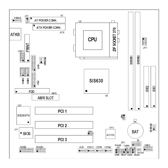
- Page 9 Jumpers Jumper Name Description Page CPU & SDRAM Frequency Setting 8-pin Block Keyboard Power ON Function 3-pin Block Setting CMOS RAM Clear 3-pin Block Connectors Connector Name Description Page AT Power Connector 12-Pin Block p.16...
-
Page 10: Chapter 2 Hardware Installation
GAME GAME Port Connector 16-Pin Block p.22 VGA Connector 16-Pin Block p.22 LAN Connector 18-Pin Block p.22 (Only for 630BF) Expansion Sockets Socket/Slot Name Description Page ZIF Socket 370 CPU Socket 370-pin FC-PGA/PPGA CPU Socket p.11 DIMM1, DIMM2 DIMM Module Socket 168-pin DIMM SDRAM Module p.13... -
Page 11: Checking Motherboard's Jumper Setting
Before using your computer, you had better complete the following steps: 1. Check motherboard setting 2. Install CPU 3. Install Memory 4. Install Expansion cards 5. Connect Ribbon cables, Panel wires, and power supply 6. Setup BIOS 7. Install software driver & utility 2-2 Checking Motherboard’s Jumper Setting CPU &... -
Page 12: Glossary
CMOS RAM Clear (3-pin): JP4 A battery must be used to retain the motherboard configuration in CMOS RAM short 2-3 pins of JP4 to store the CMOS data. Note: You can clear CMOS by shorting 1-2 pin, while the system is off. Then return to 2-3 pin position. - Page 13 BIOS (Basic Input/Output System) - the program logic used to boot up a computer and establish the relationship between the various components. Driver - software, which defines the characteristics of a device for use by another device or other software. Processor - the "central processing unit"...
-
Page 14: Setting Cpu Bus Clock & Memory Clock Jumper
2-3-2 Setting CPU Bus Clock & Memory Clock Jumper Setting the front side bus frequency and SDRAM frequency The motherboard uses jumper JP1 for the front side bus frequency and SDRAM frequency setting as shown from the table below: CPU/SDRAM (MHz) 66/66 66/100 100/100... -
Page 15: Overclock Running
When you put the CPU into the ZIF socket. No forces require to insert of the CPU, then press the level to locate position slightly without any extra force. 2-3-4 Over clock Running WARNING! This section is for experienced motherboard installer only. Over clocking can result in system instability or even shortening life of the processor. -
Page 16: Install Memory
:Move Enter:Select +/-/PU/PD:Value F10:Save ESC:Exit F1:General Help F5:Previous Values F6:Optimized Defaults F7:Standard Defaults NOTE! The BIOS allows you select Bus Frequency from 66MHz to 140MHz, the wrong setting will cause system can not starting, when it happen you have to clear CMOS and adjust correct setting for your CPU. -
Page 17: Expansion Card
NOTE! When you install DIMM module fully into the DIMM socket the eject tab should be locked into the DIMM module very firmly and fit into its indention on both sides. WARNING! For the SDRAM CLOCK is set at 133MHz, use only PC133-compliant DIMMs. -
Page 18: Interrupt Request Table For This Motherboard
Shared LAN (for 630BF Only) Shared IMPORTANT! If using PCI cards on shared slots, make sure that the drivers support “Shared IRQ” or that the cards don’t need IRQ assignments. Conflicts will arise between the two PCI groups that will make the system unstable or cards inoperable. - Page 19 2. Power Connector: ATX Power Connector (20-pin block): ATX ATX Power Supply connector. This is a new defined 20-pins connector that usually comes with ATX case. The ATX Power Supply allows to use soft power on momentary switch that connect from the front panel switch to 2-pins Power On jumper pole on the motherboard.
- Page 20 5. Parallel Printer Connector (26-pin Block): PRINT Connection for the enclosed parallel port ribbon cable with mounting bracket. Connect the ribbon cable to this connection and mount the bracket to the case on an open slot. It will then be available for a parallel printer cable. NOTE: Serial printers must be connected to the serial port.
- Page 21 8. Primary IDE Connector (40-pin block): IDE1 This connector supports the provided IDE hard disk ribbon cable. After connecting the single plug end to motherboard, connect the two plugs at other end to your hard disk(s). If you install two hard disks, you must configure the second drive to Slave mode by setting its jumpers accordingly.
- Page 22 11. Front Panel connector: This 16-pin connector to connect to case front panel switch. A. Turbo LED switch: TBLED The motherboard’s turbo function is always on. The turbo LED will remain constantly lit while the system power is on. You may also to connect the Power LED from the system case to this lead.
- Page 23 13. USB Port connector: USB1, USB2 14. FAN connector: CPUFAN, SYSFAN 15. ATX Power button: PWR BT When using ATX power, the system power can be controlled by a momentary switch connected to PS-ON Pushing the button once will switch ON/OFF the system.
- Page 24 17. CD Audio in connector : CDIN1, CDIN2 CDIN1 and CDIN2 are the connectors for CD-Audio Input signal, Please connect it to CD-ROM CD-Audio output connector. 18. Audio connector: AUDIO This connector supports the provided AUDIO cable which with mounting bracket including 3 phone Jacks: LINE-OUT, LINE-IN, MIC.
-
Page 25: Starting Up Your Computer
This connector supports the provided VGA cable with mounting bracket. Connect the ribbon cable to connector and mount the bracket to the case on a open slot. 21. LAN connector : LAN (only for 630BF) This connector supports the provided LAN cable with adaptor and mounting bracket mounting this adaptor supports standard RJ45 connector for Network connection. -
Page 26: Chapter 3 Introducing Bios
If you do not see any thing within 30 seconds from the time you turn on the power. The system may have failed on power-on test. Recheck your jumper settings and connections or call your retailer for assistance. Beep Meaning One short beep when displaying logo No error during POST Long beeps in an endless loop... -
Page 27: Entering Setup
Press (up, down, left, right) to choose, in the main menu, the option you want to confirm or to modify. Press <F10> when you have completed the setup of BIOS parameters to save these parameters and to exit the BIOS Setup menu. ... - Page 28 Advanced BIOS Features Load optimized Defaults Advanced Chipset Features Load Standard Defaults Integrated Peripherals Set Supervisor Password Power Management Setup Set User Password PnP/PCI Configurations Save & Exit Setup PC Health Status Exit Without Saving Esc : Quit : Select Item ↑↓→...
-
Page 29: Standard Cmos Features
Use this menu to load the BIOS default values for the minimal/stable performance system operation. Set Supervisor/User Password Use this menu to set User and Supervisor Passwords. Save & Exit Setup Save CMOS value changes to CMOS and exit setup. Exit Without Saving Abandon all CMOS value changes and exit setup. -
Page 30: Advanced Bios Features
Time The time format is <hour><minute><second>. Primary Master/Primary Slave Secondary Master/Secondary Slave Press PgUp/<+> or PgDn/<–> to select Manual, None, Auto type. Note that the specifications of your drive must match with the drive table. The hard disk will not work properly if you enter improper information for this category. - Page 31 Virus Warning Allows you to choose the VIRUS Warning feature for IDE Hard Disk boot sector protection. If this function is enabled and someone attempt to write data into this area, BIOS will show a warning message on screen and alarm beep. Disabled (default) No warning message to appear when anything attempts to access the boot sector or hard disk partition table.
-
Page 32: Advanced Chipset Features
During POST, BIOS will determine if the floppy disk drive installed is 40 or 80 tracks. 360K type is 40 tracks while 760K, 1.2M and 1.44M are all 80 tracks. Boot Up NumLock Status The default value is On. On (default) Keypad is numeric keys. - Page 33 CMOS Setup Utility – Copyright(C) 1984-2000 Award Software Advanced Chipset Features Advanced DRAM Control 1 Press Enter Item Help System BIOS Cacheable Enabled Video RAM Cacheable Enabled Memory Hole at 15M-16M Disabled Menu Level > AGP Aperture Size 64MB Graphic Window WR Combin Enabled Concurrent function(MEM) Enabled...
-
Page 34: Advanced Dram Control
3-6-1 Advanced DRAM Control CMOS Setup Utility – Copyright(C) 1984-2000 Award Software Advanced DRAM Control 1 Auto Configuration Auto Item Help SDRAM RAS Active Time SDRAM RAS Precharge Time RAS to CAS Delay Menu Level >> Dram Background Command Delay 1T LD-Off Dram RD/WR Cycles Delay 1T Write Recovery Time... -
Page 35: Onchip Ide Function
OnChip Device Function Please refer to section 3-7-2 Winbond SuperIO Device Please refer to section 3-7-3 Init Display First This item allows you to decide to activate whether PCI Slot or AGP VGA first. The settings are: PCI Slot, AGP Slot. 3-7-1 OnChip IDE Function CMOS Setup Utility –... -
Page 36: Onchip Device Function
Menu Level >> AMR Modem DEVICE Enabled ETHERNET Function Enabled ETHERNET Address ID Input Press Enter (Only for 630BF) Current Mac address is 003018-000001 USB Controller Enabled USB Keyboard Support Disabled ↑↓→← Move Enter:Select Item +/-/PU/PD:Value F10:Save ESC:Exit F1:General Help... -
Page 37: Winbond Superio Device
Select Enabled if your system contains a Universal Serial Bus (USB) controller and you have a USB keyboard. The settings are: Enabled, Disabled. ETHERNET Address ID Input (Only for 630BF) This item allows you to setting the Mac address from 003018 to 000001. -
Page 38: Power Management Setup
Select an address and corresponding interrupt for the first and the second serial ports. The settings are: 3F8/IRQ4, 2E8/IRQ3, 3E8/IRQ4, 2F8/IRQ3, Disabled, Auto. UART 2 Mode This item allows you to determine which InfraRed(IR) function of the onboard I/O chip, this functions uses. -
Page 39: Pm Wake Up Events
Video Off Method V/H SYNC+Blank Menu Level > Switch Function Break/Wake MODEM Use IRQ Hot key Function As Disabled HDD Off After Disabled (for ATX Power Support ) Power Button Function Instant-Off > PM Wake Up Events Press Enter ↑↓→←... -
Page 40: Pnp/Pci Configuration Setup
IRQ [3-7,9-15],NMI Enabled Item Help IRQ 8 Break Suspend Disabled Ring Power Up Control Disabled MACPME Power Up Control Disabled Menu Level >> PCIPME Power Up Control Disabled KB Power ON Password Enter for ATX Power Supply Power Up by Alarm Disabled x Month Alarm x Day of Month Alarm... -
Page 41: Irq Resources
CPU itself uses when communicating with its own special components. This section covers some very technical items and it is strongly recommended that only experienced users should make any changes to the default settings. CMOS Setup Utility – Copyright(C) 1984-2000 Award Software PnP/PCI Configurations Reset Configuration Data Disabled... -
Page 42: Pc Health Status
CMOS Setup Utility – Copyright(C) 1984-2000 Award Software IRQ Resources IRQ-3 assigned to PCI Device Item Help IRQ-4 assigned to PCI Device IRQ-5 assigned to PCI Device IRQ-7 assigned to PCI Device Menu Level > IRQ-9 assigned to PCI Device IRQ-10 assigned to PCI Device Default is Disabled. -
Page 43: Frequency/Voltage Control
Current CPU Temperature/Current System Temp/Current CPUFAN, SYSFAN Speed/ Vcore/ Vcc/3.3V/+5V/+12V/-12V/5VSB(V) This will show the CPU/FAN/System voltage chart and FAN Speed. 3-11 Frequency/Voltage Control This section is for setting CPU Frequency Control. CMOS Setup Utility – Copyright(C) 1984-2000 Award Software Frequency/Voltage Control Cyrix III Clock Ratio Default Item Help... -
Page 44: Set Supervisor/User Password
Pressing <Y> loads the BIOS default values for the most stable, minimal-performance system operations. Load Optimized Defaults When you press <Enter> on this item, you get a confirmation dialog box with a message similar to: Load Optimized Defaults (Y/N)? N Pressing <Y>... -
Page 45: Chapter 4 Driver & Free Program Installation
Additionally, when a password is enabled, you can also require the BIOS to request a password every time your system is rebooted. This would prevent unauthorized use of your computer. You determine when the password is required within the BIOS Features Setup Menu and its Security option. -
Page 46: Vga
From MAGIC INSTALL MENU you may make 8 selections: 1. VGA Install SiS 630 On-chip VGA driver 2. PC-HEALTH Install Winbond Hardware Doctor Monitoring Software 3. LAN Install PCI Fast Ethernet driver 4. SOUND Install On-chip AC’97 Audio driver 5. PC-CILLIN Install PC-CILLIN98 Anti-virus program 6. - Page 47 for LINUX is X:\SIS630\LINUX A. For WINDOWS 95/98/98SE/98ME/2000 Click VGA when Magic Install MENU Click Next when SiS630 Multimedia appears Package appears Multimedia Package support three types System will add program icons to the of Setup: Typical, Compact, Custom Program Folder listed. Click Next to continue, and after “Start Copying Files”...
-
Page 48: Pc-Health Winbond Hardware Doctor Monitoring Software
System starting install VGA driver Install Microsoft Direct X After Setup complete please select restart my computer now and click Finish to complete setup 4-2 PC-HEALTH Winbond Hardware Doctor Monitoring Software The path of the file is X:\SIS630\HEALTH-W\SETUP.EXE (Only support WINDOWS 95/98/98SE/98ME) In Windows 95/98 Winbond Hardware Doctor Monitoring Software needs some system files to copy in Utility that’s why it needs install PC-HEALTH twice to complete setup. -
Page 49: How To Utilize Pc-Health
4-3 LAN (Only for 630BF) Install SiS 900 PCI Fast Ethernet Driver The path of the file: for WINDOWS 9X/2000 is X:\SIS630\LANDRV\SETUP.EXE... -
Page 50: Install Sis 7018 Ac'97 Audio Driver And Application Software
(Including WINDOWS 95/98/98SE/98ME/2000) for WINDOWS NT4.0 is X:\SIS630\LANDRV\NT40 WINDOWS 95/98/98SE/98ME/2000 Setup Click LAN when Magic Install Menu Click NEXT when SiS PCI LAN Driver appears Setup appears Choice restart my computer now to finish After restart computer you can check in setting up LAN Card, click Finish to complete control Panel\System Device Manager\ setup... - Page 51 Click SOUND when Magic Install Menu Click Next when SiS PCI Audio Driver window appears Setup window appears Click Next to install the driver in Program Select restart my computer now and click Files Folder Finish to complete setup After restart computer the system will auto Click Audio Rack when Magic Install Menu detect SiS 7018 Audio Driver and install it to appears...
-
Page 52: Pc-Cillin Install Pc-Cillin98 Anti-Virus Software And Application Program
Run Programs Audio Rack will show next screen 4-5 PC-CILLIN Install PC-CILLIN98 Anti-virus Software and Application program Click PC-CILLIN when MAGIC INSTALL Click NEXT when PC-CILIN 98 OEM MENU Appears SETUP APPEARS. Then click YES when the announcement of copywrite appears. Software is starting to detect HD for virus Click NEXT or choose BROWSE to change 4. -
Page 53: How To Disable On-Board Sound
the path For the file to be stored NO when asked if you want PC-CILLIN To be added in ACTIVE CHANNEL or in Your internet browser If you want to make a rescue disc, insert a Choose if you want to re-start and click 1.44 MB disc Finish After install PC-CILLIN98 complete we... - Page 54 X:\FLASH\AWDFLASH.EXE or download from our web site. STEP 3. Copy latest BIOS for 630BF/630CN from our web site to your boot disc. STEP 4. Insert your boot disc into A:, start the computer, type “Awdflash A:\630BFxxx.BIN /SN/PY/CC/R” 630BFxxx.BIN is the file name of latest BIOS it can be 630BFA03.BIN or 630BFB02.BIN...