Table of Contents
Advertisement
Quick Links
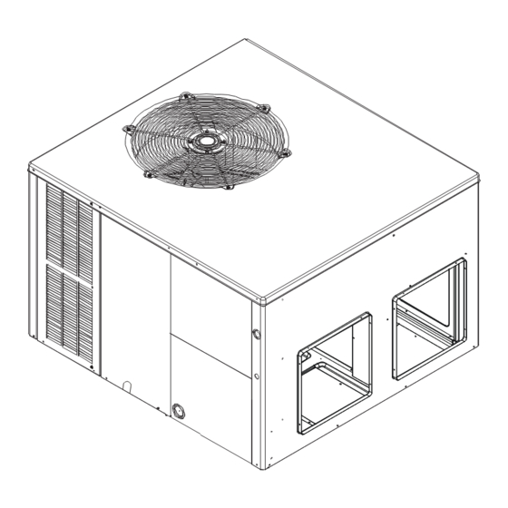
INSTALLATION INSTRUCTIONS
For Self-Contained Package
Heat Pump Units
*PHM3 & GPCM3 13.4 SEER2 "M" Series
Our continuing commitment to quality products may mean a change in specifications without notice.
IOG-3029A
10/2022
© 2022 Daikin Comfort Technologies Manufacturing, L.P.
19001 Kermier Rd. Waller, TX 77484
www.goodmanmfg.com
ONLY PERSONNEL THAT HAVE BEEN TRAINED TO
INSTALL, ADJUST, SERVICE, MAINTENANCE OR REPAIR
(HEREINAFTER, "SERVICE") THE EQUIPMENT SPECIFIED
IN THIS MANUAL SHOULD SERVICE THE EQUIPMENT. THE
MANUFACTURER WILL NOT BE RESPONSIBLE FOR ANY
INJURY OR PROPERTY DAMAGE ARISING FROM IMPROPER
SERVICE OR SERVICE PROCEDURES. IF YOU SERVICE THIS
UNIT, YOU ASSUME RESPONSIBILITY FOR ANY INJURY OR
PROPERTY DAMAGE WHICH MAY RESULT. IN ADDITION, IN
JURISDICTIONS THAT REQUIRE ONE OR MORE LICENSES
TO SERVICE THE EQUIPMENT SPECIFIED IN THIS MANUAL,
ONLY LICENSED PERSONNEL SHOULD SERVICE THE
EQUIPMENT. IMPROPER INSTALLATION, ADJUSTMENT,
SERVICING, MAINTENANCE OR REPAIR OF THE EQUIPMENT
SPECIFIED IN THIS MANUAL, OR ATTEMPTING TO INSTALL,
ADJUST, SERVICE OR REPAIR THE EQUIPMENT SPECIFIED
IN THIS MANUAL WITHOUT PROPER TRAINING MAY RESULT
IN PRODUCT DAMAGE, PROPERTY DAMAGE, PERSONAL
INJURY OR DEATH.
DO NOT BYPASS SAFETY DEVICES.
RECOGNIZE THIS SYMBOL
AS A SAFETY PRECAUTION.
WARNING
WARNING
Advertisement
Table of Contents
Troubleshooting

Related Manuals for Goodman M Series


Summary of Contents for Goodman M Series
- Page 1 INSTALLATION INSTRUCTIONS For Self-Contained Package Heat Pump Units *PHM3 & GPCM3 13.4 SEER2 “M” Series WARNING ONLY PERSONNEL THAT HAVE BEEN TRAINED TO INSTALL, ADJUST, SERVICE, MAINTENANCE OR REPAIR (HEREINAFTER, “SERVICE”) THE EQUIPMENT SPECIFIED IN THIS MANUAL SHOULD SERVICE THE EQUIPMENT. THE MANUFACTURER WILL NOT BE RESPONSIBLE FOR ANY INJURY OR PROPERTY DAMAGE ARISING FROM IMPROPER SERVICE OR SERVICE PROCEDURES.
-
Page 2: Table Of Contents
TABLE OF CONTENTS Adjusting Speed Tap for ID Blower Motor .....13 EEM Motor ..............13 [GPC/*PH] CFM Delivery and Adjustments ..13 To the Installer .............2 [GPC/*PH] Thermostat “Fan Only” Mode ....13 Shipping Inspection ............3 Superheat and Subcooling .........13 Checking Product Received ........3 Checking Subcooling ..........13 Message to the Homeowner ........3 Checking Superheat ..........13... -
Page 3: Shipping Inspection
Specification sheets can be found at: non-approved devices. www.goodmanmfg.com for Goodman® brand products or www.amana-hac.com for Amana® brand products. Within either website, please select the residential or commercial WARNING... -
Page 4: Epa Regulations
EPA Regulations “close to the wall” application minimizes exposed wiring. Important: The United States Environmental Close to the wall application assures free, unobstructed Protection Agency (EPA) has issued various air to the other two sides. In more confined application regulations regarding the introduction and spaces, such as corners provide a minimum 12”... -
Page 5: Roof Top Installation Details
Heat Pump Elevation Chart Design Temperature Suggested Minimum Elevation +15° and above 2 ½” -5° to +14° 8” Below -5° 12” Roof Top Installation (Figure 2) 1. Before locating the unit on the roof, make sure that the strength of the roof and beams is adequate to support the weight involved. -
Page 6: Circulating Air And Filters
Single phase models are shipped without horizontal duct WARNING covers. If needed, these kits may be ordered through Goodman’s Service Parts department. To prevent possible equipment damage, property damage, personal injury or death, the following bullet points must be observed when installing the unit. -
Page 7: Duct Work
Ducting Ducting work should be fabricated by the installing contractor in accordance with local codes. Industry manuals may be used as a guide when sizing and designing the duct system-such as NESCA (National Environmental Systems Contractors Association, 1501 Wilson., Arlington, Virginia 22209). The unit should be placed as close as possible to the space to be air-conditioned allowing clearance dimensions as indicated. -
Page 8: Condensate Drain Piping
CONDENSATE DRAIN PIPING bring in the power supply to the contactor as shown on the unit wiring diagram which is supplied with each unit. The The condensate drain connection of the evaporator is a low voltage wiring must be connected between the unit ¾”... -
Page 9: Low Voltage Wiring
START-UP PROCEDURES AND Low Voltage Wiring Air Conditioners – Connect 24V wires from the thermostat CHECKLISTS to the corresponding wires in the control box using No. 18 Begin with power turned off at ALL disconnects. AWG as follows: WARNING GPCM3 Terminal Thermostat HIGH VOLTAGE! -
Page 10: Final System Checks
COMPONENTS unit time to settle out, make sure the unit is supplying heated air. Contactor – This control is activated (closed) by the room 4. If the outdoor ambient is above 80°F, the unit may trip thermostat for both heating and cooling. The contactor on its high-pressure cutout when in heating mode. -
Page 11: Heat Pump Operation
HEAT PUMP OPERATION For 5-Ton Heat Pump unit, the expansion devices are Thermal Expansion Devices (TXV) and perform the same Cooling Cycle function on the heating cycle as on the cooling cycle. The When the heat pump is in the cooling cycle, it operates TXVs also act as check valves to allow for the reverse of exactly as an Air Conditioner Unit. -
Page 12: Suggested Field Testing/Troubleshooting
Suggested Field Testing/Troubleshooting TESTING DEFROST CONTROL NOTE: PCBDM133 Defrost controls have a three (3) minute compressor off cycle delay. NOTE: The PCBDM133 defrost controls are shipped from the factory with the compressor delay option selected. This will de-energize the compressor contactor for 30 seconds on defrost initiation and defrost termination. -
Page 13: Adjusting Speed Tap For Id Blower Motor
[GPC/*PH]M3 Thermostat “Fan Only” Mode During Fan Only Operations, the CFM output is 50% of the high stage cooling setting. SUPERHEAT AND SUBCOOLING Checking Subcooling NOTE: Units with a TXV should be charged to Subcooling only. EXAMPLE: a. Liquid Line Pressure = 417 PSI b. -
Page 14: Electric Heat Installation & Adjustment
ELECTRICAL HEAT INSTALLATION & Design Superheat & Subcooling ADJUSTMENT Superheat Subcooling Expansion Cooling Outdoor Model ±2°F ±1°F Device Stage ambient (°F) Heater Kit GPCM32441 Orifice High NOTE: A separate power supply is required for GPCM33041 Orifice High HKR/HKP Heater Kits. GPCM33641 Orifice High... -
Page 15: Service
REVERSING VALVE TROUBLESHOOTING supply registers should be free of any obstructions. The filters should be cleaned or replaced. These few steps Checking Reversing Valve and Solenoid will help to keep the product up time to a maximum. The Reversing valve used in heat pumps could potentially leak Troubleshooting Chart (see Appendix) should help in internally. -
Page 16: Poor "Terminating" Sensor Contact
If voltage is registered at the coil, tap the valve body lightly while switching the system from HEATING to COOLING, etc. If this fails to cause the valve to switch positions, remove the coil connector cap and test the continuity of the reversing valve solenoid coil. -
Page 17: Troubleshooting Chart
TROUBLESHOOTING CHART POSSIBLE CAUSE REMEDY SYMPTOM High head - low suction a. Restriction in liquid line or flowrator a. Remove or replace with proper size flowrator. High head - high or normal suction a. Dirty condenser coil a. Clean coil b. -
Page 18: Blower Performance Data
GPCM3[24-60]41** BLOWER PERFORMANCE DATA Horizontal Flow Motor Compressor E.S.P. (In. of H Model Volts stage Single stage Watts 1133 1081 1026 T2/T3 Single stage Watts 1230 1190 1140 1095 1040 T4/T5 Single stage Watts Single stage Watts 1271 1222 1176 1129 1081 1026... - Page 19 GPCM3[24-60]41** BLOWER PERFORMANCE DATA Down flow Motor Compressor E.S.P. (In. of H Model Volts stage Single stage Watts 1065 1016 T2/T3 Single stage Watts 1156 1119 1072 1029 T4/T5 Single stage Watts Single stage Watts 1195 1148 1106 1061 1016 T2/T3 Single stage Watts...
- Page 20 *PHM3[24-60]41** BLOWER PERFORMANCE DATA Horizontal Flow Motor Compressor E.S.P. (In. of H Model Volts stage Single stage Watts 1114 1068 1017 T2/T3 Single stage Watts 1371 1316 1281 1240 1186 1133 1072 1000 T4/T5 Single stage Watts Single stage Watts 1347 1295 1243...
- Page 21 *PHM3[24-60]41** BLOWER PERFORMANCE DATA Down flow Motor Compressor E.S.P. (In. of H Model Volts stage Single stage Watts 1085 1019 T2/T3 Single stage Watts 1355 1300 1254 1201 1147 1084 1007 T4/T5 Single stage Watts Single stage Watts 1302 1257 1198 1148 1089...
-
Page 22: Unit Dimensions
DIMENSIONS DIMENSION MEDIUM LARGE (INCHES) MEDIUM CHASSIS [GPC/*PH] M32441 [GPC/*PH] M33041 [GPC/*PH] M33641 LARGE CHASSIS [GPC/*PH] M34241 [GPC/*PH] M34841 [GPC/*PH] M36041 MINIMUM CLEARANCES NOTE: Roof overhang Should be no more than 48”... -
Page 23: Homeowner's Routine Maintenance
PACKAGE UNITS - HEAT PUMP AND AC UNITS HOMEOWNER’S ROUTINE MAINTENANCE RECOMMENDATIONS WE STRONGLY RECOMMEND A BI-ANNUAL MAINTENANCE CHECKUP BE PERFORMED BY A QUALIFIED SERVICE AGENCY BEFORE THE HEATING AND COOLING SEASONS BEGIN. flush the coil with water. This cleaning practice remains as WARNING the recommended cleaning method for both copper tube and aluminum tube residential cooling coils. -
Page 24: Start-Up Checklist
START-UP CHECKLIST Residential Package - (Indoor Section) Model Number Serial Number ELECTRICAL Line Voltage (Measure L1 and L2 Voltage) L1 - L2 Secondary Voltage (Measure Transformer Output Voltage) R - C Blower Amps Heat Strip 1 - Amps Heat Strip 2 - Amps BLOWER EXTERNAL STATIC PRESSURE Return Air Static Pressure IN. - Page 25 THIS PAGE INTENTIONALLY LEFT BLANK...
- Page 26 THIS PAGE INTENTIONALLY LEFT BLANK...
- Page 27 THIS PAGE INTENTIONALLY LEFT BLANK...
- Page 28 CUSTOMER FEEDBACK We are very interested in all product comments. Please fill out the feedback form on one of the following links: Goodman Brand Products: (http://www.goodmanmfg.com/about/contact-us). ® Amana Brand Products: (http://www.amana-hac.com/about-us/contact-us). ® You can also scan the QR code on the right for the product brand you purchased to be directed to the feedback page.