Table of Contents
Advertisement
Quick Links
Advertisement
Table of Contents

Related Manuals for Daikin FWC02G


Summary of Contents for Daikin FWC02G
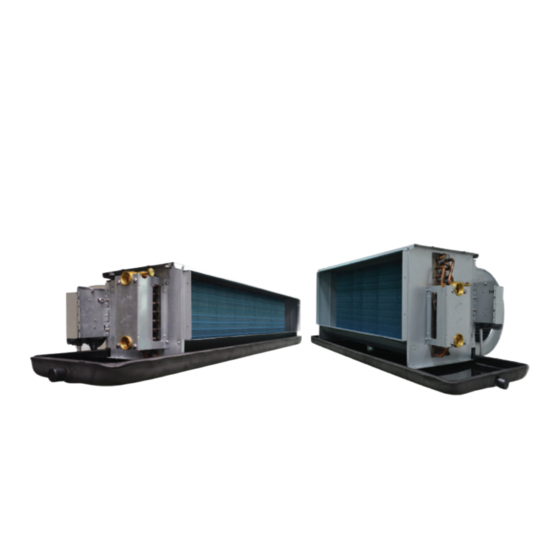
- Page 1 INSTALLATION MANUAL CEILING CONCEALED CHILLED WATER FAN COIL UNIT (G SERIES) Installation Manual English Chilled Water Fan Coil Unit MODELS FWC02G FWC03G FWC04G FWC06G FWC08G FWC10G FWC12G FWC14G FWC16G FWC18G FWC20G IM-CCGW-0821(5)-DAIKIN Part Number.: R08019045598...
-
Page 2: Outline And Dimensions
OUTLINE AND DIMENSIONS Indoor Unit: Ceiling Concealed Fan Coil Unit G Series All dimensions are in mm FWC02G MOUNTING HOLE (4 X 10.0 X 16.0) CONDENSATE DRAIN (R3/4") WATER OUT (3/4" BSPT FEMALE THREAD ADAPTOR) WATER IN (3/4" BSPT FEMALE THREAD ADAPTOR) - Page 3 All dimensions are in mm FWC12G MOUNTING HOLE (4 X 10.0 X 16.0) CONDENSATE DRAIN (R3/4") WATER OUT (3/4" BSPT FEMALE THREAD ADAPTOR) WATER IN (3/4" BSPT FEMALE THREAD ADAPTOR) All dimensions are in mm FWC14/16/18/20G MOUNTING HOLE (4 X 10.0 X 16.0) CONDENSATE DRAIN (R3/4") WATER OUT (1"...
- Page 4 Indoor Unit: Ceiling Concealed Fan Coil Unit G Series with Plenum Box Option. FWC02/03/04/06/08/10/12G All dimensions are in mm MOUNTING HOLE (6 X 10.0 X 16.0) CONDENSATE DRAIN (R3/4") WATER OUT (3/4" BSPT FEMALE THREAD ADAPTOR) WATER IN (3/4" BSPT FEMALE THREAD ADAPTOR) FWC14/16/18/20G All dimensions are in mm MOUNTING HOLE...
-
Page 5: Safety Precautions
INSTALLATION MANUAL This manual provides the procedures of installation to ensure a safe and good standard of operation for the air conditioner unit. Special adjustment may be necessary to suit local requirement. Before using your air conditioner, please read this instruction manual carefully and keep it for future reference. This appliance is intended to be used by expert or trained users in shops, in light industry and on farms, or for commercial use by lay persons. -
Page 6: Installation Of The Indoor Unit
INSTALLATION OF THE INDOOR UNIT The indoor unit must be installed such that there is no short Ceiling Concealed Mounting circuit of the cool air discharge. Respect the installation • Use the hanger supplied with the unit. clearance. Do not put the indoor unit where there is direct •... -
Page 7: Important Notice
IMPORTANT NOTICE INSULATION THROUGH OUT CHILLED WATER PIPING CORK TAPE FULLY INSTALLED SEE VIEW FROM BOTTOM SEE VIEW A INSULATION MUST COVER ALL THE DRAIN PIPE VIEW A DRAIN PIPE INSULATE SECURELY VIEW FROM BOTTOM WATER PIPING CONNECTION • The indoor unit is equipped with water outlet and inlet connection. There is an air-vent that is fitted along with the connection for air purging. -
Page 8: Electrical Wiring Connection
ELECTRICAL WIRING CONNECTION FWC02/03/04/06/08/10/12/14/16/18/20G FCU 1 FCU 2 FCU 3 220-240V/~/50Hz or 220-240V/~/50Hz or 220-240V/~/50Hz or 208-230V/~/60Hz 208-230V/~/60Hz 208-230V/~/60Hz Fan Low Chiller There must be an all pole Fan Medium Fan High disconnection in the supply mains Neutral with a contact separation of at Fan Speed Controller least 3mm. - Page 9 ELECTRICAL WIRING CONNECTION FWC02/03/04/06/08/10/12G EC (Variable Speed) -7 2 8 -7 2 8 -7 2 8 2 4 5 +6 2 4 5 +6 2 4 5 +6 There must be an all pole disconnection in the supply mains 1 2 2 8 !, with a contact separation of at 2 8 $ "...
-
Page 10: Operating Range
Model (FWC) Indoor Voltage Range** Indoor 220V-240V/ ~ /50Hz + ! or 208V-230V/ ~ /60Hz + ! Power Supply Cable Size* Number of Conductors 5 or 6 5 or 6 5 or 6 5 or 6 5 or 6 5 or 6 Recommended Time Delay Fuse* Model (FWC) Indoor... -
Page 11: Overall Checking
OVERALL CHECKING • Ensure that: • Test run: The unit has been mounted solidly and is in a rigid Conduct a test run on the unit after having perform the position. water drainage test and the gas leakage test. The piping and connections are leak-proof. Check the following items: Proper wiring has been installed. - Page 12 INTERCHANGEABLE HEAT EXCHANGER PIPING DIRECTION GUIDE LINE The simulation below is based on FCU FWC-G Unit. From right piping direction to left piping direction. To perform this simulation, please seek advice from the trained staff. This simulation required minimum of two trained servicemen. ! WARNING Changing the original HEAT EXCHANGER PIPING DIRECTION will cause performance drop of 15% to 20%.
- Page 13 STEP 5 - Unscrew the Control Box Right Side Panel to the Left Side Panel and screw. TO LEFT FROM RIGHT CONTROL CONTROL STEP 6 - Slowly lift the Heat Exchanger from the Hairpin Side STEP 7 - While holding Heat Exchanger, gently move out the upwards and also at the same time gently pull the Side Heat Exchanger Distributor from the Side Panel.
- Page 14 STEP 10 - Then gently pull the Side Panel outwards to allow STEP 9 - Start assembles the Heat Exchanger back into the the Hairpin side of the Heat Exchanger enter the unit by entering the Heat Exchanger Distributor into unit.
-
Page 15: Service And Maintenance
SERVICE AND MAINTENANCE Service Parts Maintenance Procedures Period Indoor Air Filter Remove any dust adhered on the filter by using a vacuum cleaner or wash At least once every in lukewarm water (below 40°C) with neutral cleaning detergent. 2 weeks. Rinse well and dry the filter before placing it back onto the unit. - Page 16 Head offi ce: Lot 10, Jalan Perusahaan 8, Umeda Center Bldg., 2-4-12, Nakazaki-Nishi, Kawasan Perusahaan Pekan Banting, Kita-ku, Osaka, 530-8323 Japan 42700 Banting, Selangor D.E., Malaysia. Tokyo offi ce: JR Shinagawa East Bldg., 2-18-1, Konan, Minato-ku, Tokyo, 108-0075 Japan http://www.daikin.com/global/...