Table of Contents
Advertisement
Quick Links
INSTALLATION
MANUAL
Models
FWF02CATNMV1
FWF03CATNMV1
FWF04CATNMV1
Kaltwasser-Ventilatorluftkühler
Ventilo-convecteur à eau glacée
Koudwater-Ventilatorluchtkoeler
Unidades de serpentín de ventilador de agua fría
Unità fan coil ad acqua fredda
Unidades de bobina de ventilador de água refrigerada
Вентиляторные доводчики с водяным охлаждением
Installation Manual
Chilled Water Fan Coil Units
Installationshandbuch
Manuel d'installation
Installatiehandboek
Manual de instalación
Manuale Di Installazione
Manual De Instalação
Руководство По Установке
Kurulum Kılavuzu
So¤uk su fan bobin üniteleri
IM-CKCW-0706(1)-Daikin (DENV)
Part No.: R08019029229A
English
Deutsch
Français
Nederlands
Español
Italiano
Ελληνικά
Portugues
Русский
Türkçe
Advertisement
Table of Contents

Related Manuals for Daikin FWF02CATNMV1


Summary of Contents for Daikin FWF02CATNMV1
- Page 1 Español Unidades de serpentín de ventilador de agua fría Manuale Di Installazione Italiano Unità fan coil ad acqua fredda Ελληνικά Models FWF02CATNMV1 Manual De Instalação Portugues Unidades de bobina de ventilador de água refrigerada FWF03CATNMV1 FWF04CATNMV1 Руководство По Установке Русский...
-
Page 3: Outline And Dimensions
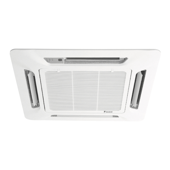
OUTLINE AND DIMENSIONS Indoor Unit: Ceiling Cassette Fan Coil Unit C Series. SEE DETAIL A WATER INLET WATER OUTLET DETAIL A All dimensions are in mm Dimension Model FWF02CATNMV1 / FWF03CATNMV1 / FWF04CATNMV1... -
Page 4: Safety Precautions
INSTALLATION MANUAL This manual provides the procedures of installation to ensure a safe and good standard of operation for the air conditioner unit. Special adjustment may be necessary to suit local requirement. Before using your air conditioner, please read this instruction manual carefully and keep it for future reference. This appliance is intended to be used by expert or trained users in shops, in light industry and on farms, or for commercial use by lay persons. -
Page 5: Important Notice
IMPORTANT NOTICE CORK TAPE FULLY INSULATED INSULATION THROUGH OUT CHILLED WATER PIPING INSTALLATION OF THE INDOOR UNIT Preliminary Site Survey Min. 0.5 m Min. 0.5 m Min. 0.5 m Obstacle Floor • Voltage supply Á uctuation must not exceed ±10% of rated voltage. Electricity supply lines must be independent of welding transformers which can cause high supply Á... - Page 6 Unit Installation • Measure and mark the position for the hanging rod. Drill the hole for the angle nut on the ceiling and À x 15.0 538.0 18.0 the hanging rod. • The installation template is extended according to temperature and humidity. Check on dimensions in use.
- Page 7 Cover Lock Grille (The moving part protection for user direct touching) Cover lock grille must be installed as the À gure below. Frame Intake Grille Cover Lock Grille (2pcs) Screw M4 x 6 (2pcs) If the unit need to be service, steps below shall be followed: 1.
- Page 8 Water Piping Connection • The indoor unit is equipped with water outlet and inlet connection. There is an air-vent that is À tted along with the connection for air purging. • 3 ways valve is required for cycling off or bypass the chilled water. •...
-
Page 9: Electrical Wiring Connection
ELECTRICAL WIRING CONNECTION This is proposed wiring connection. It may change subject to the chiller unit and must comply with the local and national code and regulations. Model: FWF02CATNMV1 / FWF03CATNMV1 / FWF04CATNMV1 FCU 1 FCU 2 FCU 3 VALVE... -
Page 10: Operating Range
• All wires must be À rmly connected. • Make sure all the wire do not touch the refrigerant pipings, compressor or any moving parts. • The connecting wire between the indoor unit and the outdoor unit must be clamped by using provided cord anchorage. -
Page 11: Indicator Lights
INDICATOR LIGHTS Remote Control When there is infrared remote control operating signal, the signal receiver on indoor unit will make a <beep> for signal acceptance conÀ rmation. Error Description Cool LED Error Indication Room Sensor error 1 blink Pipe water sensor error 2 blinks Water pump error 6 blinks... -
Page 12: Troubleshooting
TROUBLESHOOTING For any enquiries on spare parts, please contact your authorized dealer. If any malfunction of the air conditioner unit is noted, immediately switch off the power supply to the unit. Check the following fault conditions and causes for some simple troubleshooting tips. Fault Causes/Action 1. - Page 13 MEMO / MITTEILUNG / LE MÉMO / MEMO / EL MEMORÁNDUM / PROMEMORIA / ΣΗΜΕΙΩΜΑ / MEMO / ПАМЯТКА / NOT...
- Page 16 In the event that there is any confl ict in the interpretation of this manual and any translation of the same in any • language, the English version of this manual shall prevail. The manufacturer reserves the right to revise any of the specifi cation and design contain herein at any time •...