
Related Manuals for Daikin FWC06B7TV1B


Summary of Contents for Daikin FWC06B7TV1B
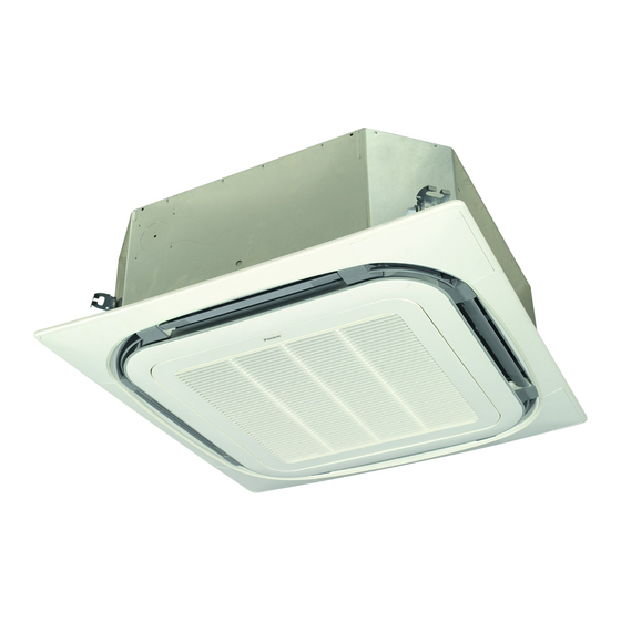
- Page 1 INSTALLATION MANUAL Fan coil units FWC06B7TV1B FWC07B7TV1B FWC08B7TV1B FWC09B7TV1B FWC06B7FV1B FWC07B7FV1B FWC08B7FV1B FWC09B7FV1B Cover Cover Type numbers...
- Page 2 ≥1500 ≥1500 1-1.5 m FWC_T 2x FWC_T 2x FWC_T 2x FWC_F 4x FWC_F 4x FWC_F 4x 1~1.5 m A-A' ≤4 mm P1 P2 F1 F2 T1 T2 10~15 mm 7 mm 70~90 mm...
- Page 3 3PW66183-2...
-
Page 4: Table Of Contents
The heat exchanger receives hot or cold water from a heating or cooling source. 3.1. Check that you have all optional DAIKIN offers a wide range of fan coil units for both concealed and equipment exposed applications. Contact your DAIKIN dealer for a list of related 3.2. -
Page 5: Meaning Of Warnings And Symbols
If not sure of installation procedures or operation of the unit, always all connected units. contact your local DAIKIN dealer for advice and information. Unified ON/OFF DCS301BA51 Remote controller to controller... -
Page 6: Verify The Appropriate Installation Location
Prepare the installation of the fan coil unit Sensor Identification code Description Information Remote temperature KRCS01-4 Replacement sensor Leave 200 mm or more space where marked with *, on sensor to measure sides where the air outlet is closed. temperature remotely Refer to figure 2: “Space required for installation”. -
Page 7: Prepare The Electrical Wiring Work
Prepare the installation of the fan coil unit 3.5. Prepare the electrical wiring work Specifications for field wiring The unit must be connected to the power supply. All field wiring and Wire Size (mm²) Length components must be installed by an installer and must comply with the (a),(b) Power supply According to... -
Page 8: Check If All Accessories Are Included
Sealing pad for piping connections All the above parts are field supplied. For installation other than standard installation, Install the fan coil unit contact your local DAIKIN dealer for advice. 4.3. Prepare the ceiling opening See figure 11: “Opening in ceiling”... -
Page 9: Perform The Water Piping Work
Install the fan coil unit 4.5. Perform the water piping work Adjust the unit to the right position for installation. Use the installation guide (delivered with the unit) for exact Install the fan coil unit vertical positioning of the unit. 4.5.1. -
Page 10: Fill The Water Circuit
Install the fan coil unit 4.5.3. Fill the water circuit Remote controller wiring should be located at least 50 mm away from the unit transmission wiring and other wiring. Failure to observe this guideline may result in malfunction due to electrical Notice noise. -
Page 11: Connect The Power Supply
Install the fan coil unit 4.6.1. Connect the power supply Light emitting diode (filter sign - red) See figure 9: “How to connect electrical wiring”. Light emitting diode (defrost - orange) Selector switch (main/sub) Control box cover Selector switch (wireless address set) Wiring diagram sticker Power supply cable intake Power supply terminal block –... -
Page 12: Connect The Drain Piping To The Unit
Install the fan coil unit 4.7.3. Test the drain piping Keep piping as short as possible and slope it downwards at a gradient of at least 1/100 so that air does not remain trapped After the drain piping work is finished, check if drainage flows inside the pipe. -
Page 13: Commission The Fan Coil Unit
(3 There is no water leakage inside the unit. blocks) If there is water leakage, close the water inlet and water outlet shut-off valves and call your local DAIKIN dealer. KJB411A Electrical box — All air is removed from the circuit. -
Page 14: Configure The Unit
After installation, the installer is obliged to verify correct operation. >3.2 or ≤3.6 13(23) In case something is wrong with the unit and it does not operate, contact your local DAIKIN dealer. >3.6 or ≤4.2 13(23) Information Table 5.2: Ceiling height setting When using a wireless remote controller, conduct a test operation after installing the decoration panel. -
Page 15: Service And Maintenance
Danger: electric shock In case some part is damaged and needs to be replaced, call your “Precautions for installation” on page local DAIKIN dealer or the appointed service company for a list of available spare parts. Information Danger: high temperature Before starting the troubleshooting procedure, carry out a “Precautions for installation”... - Page 19 860~910 860~910...
- Page 20 Cover Rear Cover Rear 4PW64525-1B 2014.03...