Advertisement
Owner's
Manual
®
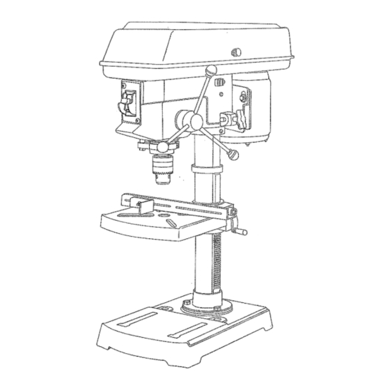
Bench
Mode_
1/2 HP (Maximum
Developed)
5 Speeds
(540 = 3600 R,PoMo)
!/2 inch
Chuck
104NCH DR_LL PRESS
Model No°
137o219100
CAUTmON°o
Before using this Dril! Press,
read this manual and foltow
at! its Safety Rules and
Operating
Instructions.
• Safety _nstructions
o KnstatJation
o Operation
o Maintenance
o Parts List
o Espa_oi
@ustemer
He_p L_n÷
t °8@@°843°1682
Sears, Roebuck
and Co=, Hoffman
Estates,
mL60179 USA
Part No. 1372!910001
Advertisement
Table of Contents

Related Manuals for Craftsman 137.2191


Summary of Contents for Craftsman 137.2191
- Page 1 Owner's Manual Bench Mode_ 1/2 HP (Maximum Developed) 5 Speeds (540 = 3600 R,PoMo) !/2 inch Chuck 104NCH DR_LL PRESS Model No° 137o219100 CAUTmON°o Before using this Dril! Press, read this manual and foltow at! its Safety Rules and Operating Instructions.
-
Page 2: General Safety Instructions
£aOTOR ... 120V, 60 HZ, 6 AMPS, HORSEPOWER ... 1/2 HP (Max. Developed) Your drill press is wired at the fac[[ory for 120V operation. Connect to a 120V, t5 AMP branch circuit and use a TABLE SIZE ... 8-!/4" x 7-1/4"... - Page 3 SPECnFIC SAFETY NSTRUCTMONS FOR THE DR LL PRESS For your own safety, do not try to use your drill press or plug it in until it is completely assembled and installed according tO the instructions, and until you have read and...
-
Page 4: Available Accessories
UNPACKmNG AND CHECKmNG CONTENTS Use only accessories recommended [or this drill press. If any part is missing or damaged, do not plug the drill Follow instruction,s that accompany accessories, Use of press in until the missing or damaged part is replaced, improper accessories may cause hazards. - Page 5 Fence backstop Fence end__ ,: !. ::::, BASE - Supports the drill press. For additional stability, holes are provided in the base to bolt the drill press to Motor Spindle the floor. (See "Specific Safety Instructions for Drill Presses':) pulley...
- Page 6 (1) on the inside of the table support is engaged with the teeth of the rack. Fig. C Drill Press is very heavy and MUST be lifted with the help of 2 PEOPLE OR MORE, to safely assemble it. COLUMN SUPPORT TO BASE (FIG. A) Position base (1)on floor.
- Page 7 Clean tapered surfaces on the spindle (2). MOUNTING DRILL PRESSTO WORK SURFACE (FIG. L) If mounting the drill press to a workbench, a solid CAUTION: Make sure there are no foreign particles wood bench is preferred over a plywood board, to sticking to the surfaces.
- Page 8 Figure O on page 13. To unlock the belt tension, loosen the belt tension lock knobs (1) on both sides of the drill press head. Move the motor (2) toward the front of the drill press to loosen the belt.
- Page 9 With the key removed from the switch, unauthorized and hazardous use by children and others is minimized. To turn the drill press "ON", insert key (1) into the slot of the switch (2), and move tile switch upward to the "ON"...
- Page 10 POSITIONING THE TABLE AND WORKPiECE (FIGURE AA and IBB) Lock the table (!) to the column (2) at a position so the tip of the drill bit (3) is just above the top of the workpiece (4). ALWAYS place a BACK-UP MATERIAL (scrap wood) on the table beneath the workpiece.
-
Page 11: Troubleshooting
LUbrICATiON _ubricating your drill press. A!l of the drill press ball beadngs are packed with 9tease Frequentiy blow out using an air compressor or dust at the factory. They require no further k_bdcation. -
Page 12: Drill Press
Use of any other parts may create a HAZARD or cause product damage. Any attempt to repair or replace electrical parts on this Drill Press may create a HAZARD unless repair is done by a qualified service technician. Repair service is available at your nearest Sears Service Center.