Table of Contents
Advertisement
Quick Links
Advertisement
Table of Contents
Troubleshooting

Related Manuals for NAiS FP2


Summary of Contents for NAiS FP2
- Page 1 PROGRAMMABLE CONTROLLER FP2 Multi Communication Unit Technical Manual This manual was created using Adobe Acrobat. Adobe, the Adobe logo, and Acrobat are trademarks of Adobe Systems Incorporated. FP2 Multi Communication Unit Techinical Manual ARCT1F396E-1 ’04.9 http://www.naisplc.com/...
-
Page 3: Table Of Contents
1.3 Restrictions on Units Combination ................1-5 1.3.1 Restrictions on Installation position and Number of Units ..........1-5 Specifications and Functions .............. 2-1 2.1 FP2 Multi Communication Unit ..................2-2 2.1.1 Parts and Functions ....................2-2 2.2 FP2 Communication Blocks ...................2-4 2.2.1 Types of Communication Blocks.................2-4 2.2.2 Names and Major Applications of Port................2-6... - Page 4 4.1.2 General-purpose Serial Communciation Mode............4-4 4.1.3 Computer Link Mode....................4-4 4.2 Remote Control using Modem ..................4-5 4.3 Settings..........................4-6 4.3.1 Operation Mode Setting ....................4-6 4.3.2 Communication Condition Setting................4-6 4.3.3 Unit No. Setting ......................4-7 4.4 How to Set ........................4-8 4.4.1 Unit No. Setting Switch ....................4-8 4.4.2 Mode Speed Setting Switch ..................4-8 4.4.3 Memory Switch......................4-9 4.4.4 Flow Chart .........................4-10...
- Page 5 6.4.1 Programming Example of General-purpose Serial Communication......6-8 6.5 Data Transmission F159 (MTRN) Instruction..............6-9 6.6 Data Reception F161 (MRCV) Instruction..............6-12 6.6.1 Data to be Sent/Received with MCU ................6-14 6.6.2 Flag Operation in Serial Communication ..............6-15 6.7 Connection with 1:1 Communication (General-purpose Serial Communication) ..6-18 6.7.1 Connection Example with External Device <1:1 Communication with Micro- Imagechecker>........................6-19 6.7.2 Connection Example with External Device <1:1 Communication with FP Series PLC >...
- Page 6 9.1.4 I/O Allocation (General-purpose Serial Communication)..........9-7 9.2 Appendix...........................9-9 9.2.1 Detailed Time Chart of Data Transmission and Reception.........9-9 9.2.2 Time Chart of Multiplex Reception................9-10 10 Dimensions and Sample Programs ........... 10-1 10.1 Dimensions........................10-2 10.1.1 FP2 Multi Communication Unit................10-2 10.1.2 Communication Blocks....................10-3...
-
Page 7: Before You Start
FP2 communication block must be installed for using FP2 Multi Communication Unit. Difference from the conventional models • FP2-SDU FP2-SDU and FP2 Multi Communication Unit is not interchangeable as all uses such as settings or commands are different. • FP2-CCU... -
Page 9: Functions And Restrictions Of The Unit
Chapter 1 Functions and Restrictions of the Unit... -
Page 10: Features And Functions Of The Unit
Features and functions of Multi Communication Unit Multi Communication Unit is a communication interface to be used with the programmable controller FP2/FP2SH to connect with serial communication devices. Multi Communication Unit corresponds to multiple communication modes and standards, and has features as below. - Page 11 High-speed and large-capacity communciation MCU corresponds to 230 kbps-high-speed communication. Also 2048 characters data per frame can be transmitted. Note) When setting to 230400 bps, use USB ports at computers. If connecting to RS232C ports, a device open error occurs and communication is not available. Stable communication by double insulation As the areas between the internal circuits and between channels are electrically insulated, it is irrefrangible, and has less effect on connecting devices.
-
Page 12: Unit Types
AFP2803 FP2 communication block (RS422) RS422 FP2-CB422 AFP2804 FP2 communication block (RS485) RS485 FP2-CB485 AFP2805 Note: FP2 communication block is necessary for FP2 Multi Communication Unit.s FP2 Multi Communication Unit cannot be used alone. Use it with FP2 communication block. -
Page 13: Restrictions On Units Combination
Install two units within five units in combination with W link, CCU and PC(PLC) link MCU. *2 When using both FP2/FP2SH: Up to two units, including W link mode set to PC (PLC link) mode, can be used. *1 General-purpose serial Can be installed in any position. -
Page 15: Specifications And Functions
Chapter 2 Specifications and Functions... -
Page 16: Fp2 Multi Communication Unit
2.1 FP2 Multi Commu nication Unit 2.1.1 Parts and Functions Operation indicator LEDs Status indicator LED Display Operation Send Data Flashes while data is being sent. Green monitor Goes out when no data is being sent. Flashes while data is being received. - Page 17 Installation position for communication block The communication blocks are installed in COM.1 and COM.2. Unit No. setting switch Unit No. for the COM.1 is set when the PC(PLC) link and computer link is selected for the operation mode. Unit No. can be selected in a range of 1 to 15. •...
-
Page 18: Fp2 Communication Blocks
Types of Communication Blocks There are three types of communication cassettes, each having a particular field of application. FP2 communication block (RS232C) FP2-CB232 (AFP2803) This communication block is a 1-channel unit with a five-wire RS232C port. It supports 1:1 computer links, general-purpose serial communication and PC(PLC) link between two units. - Page 19 FP2 communication block (RS485) FP2-CB485 (AFP2805) This communication block is a 1-channel unit with a two-wire RS485 port. It supports 1:N computer link, general-purpose serial communication and the PC(PLC) link. Name Abbr. Signal direction Terminal station setting Transmission line (-)
-
Page 20: Names And Major Applications Of Port
2.2.2 Names and Major Applications of Port Two communication ports are equipped with FP2 Multi Communication Unit (MCU). By mounting either communication blocks, RS232C, RS422 or RS485, the communication becomes available with external devices. The upper communciation port is called COM. 1 port, and the lower port is called COM. -
Page 21: Table Of Specifications
2.3 Table of Specifica tions 2.3.1 General Specifications Item Description Ambient temperature 0 to +55 °C Storage temperature -20 to +70 °C Ambient humidity 30 to 85% RH (at 25 °C non-condensing) Storage temperature 30 to 85% RH (at 25 °C non-condensing) Vibration resistance 10 to 55 Hz, 1 cycle/min, double amplitude of 0.75 mm 10 min on X, Y, Z axes... -
Page 22: Communication Specifications
2.3.2 Communication Specifications General-purpose Computer link Serial communication (PC) PLC link 1:1 communi- 1:N communi- 1:1 communi- Item communi- Note1) Note1) Note1) cation cation cation Note1) cation AFP2803 AFP2805 AFP2805 2803 2804 2803 2804 AFP2805 RS232C Interface RS232C RS422 RS485 RS232C RS422 RS485... - Page 23 operation using the actual device. In some cases, the number of units, transmission distance, and baud rate vary depending on the connected device. Note3)The values for the transmission distance, baud rate and number of units should be within the values noted in the graph below. When using a baud rate of 2400 bps to 38400 bps, you can set up to a maximum of 99 units (stations) and maximum transmission distance of 1200 m.
- Page 24 Precaution when using RS485 port RS485 communication is a communication method to perform sending and receiving by two-wire system. Therefore, only one device enables to send data in the communication line at the same time. Multi Communication Unit (MCU) can send back responses (send data) instantaneously for the transmitted data from other devices However, depending on other devices connected, it may need a time to open the communication line.
-
Page 25: Confirming The I/O Contacts And Slot Number
2.4 Confirming the I/O Contacts and Slot Number 2.4.1 The Role of Input/Output Contacts. Multi Communication Unit (MCU) has input/output contacts which enable communication with the CPU unit. (They are mainly used in the general-purpose serial communication.) These contacts play various roles, such as alerting the CPU unit when sending and reception have been completed, alerting when an error has occurred, or resetting the port of MCU. -
Page 26: Confirming The I/O Number Allocation
• If the CPU unit being used is a 2-module type, also check any I/O areas occupying the units incorporated in the CPU unit. Reference: For information on how I/O allocations are made, refer to <FP2/FP2SH Hardware Manual>. 2-12... -
Page 27: Confirming Slot Number
2.4.3 Confirming Slot Number When mounted on the CPU backplane Slots are numbered in sequential order, with the slot to the right of the CPU unit being No. 0. Note: If the CPU unit being used is a 2-module type, the slot number of the units incorporated in the CPU unit should be counted as “0”. -
Page 28: Confirming Root No
2.4.4 Confirming Root No. If multiple Multi Communication Units (MCU) have been installed, they are labeled “Root No. 1”, “Root No. 2” and “Root No. 3” in sequential order, starting from the unit closest to the CPU unit. Root numbers are not used directly in the handling of the Multi Communication Unit, but if a Multi-wire Link Unit (when setting MEWNET-W mode or MEWNET-W2 mode), an ET-LAN unit or a computer communication unit is being used at the same time, these numbers are sometimes specified on the Multi-wire Link Unit or the ET-LAN unit side. -
Page 29: Installation And Wiring Of Communication Blocks
Chapter 3 Installation and Wiring of Communication Blocks... -
Page 30: Installation Of Communication Blocks
3.1 Installation of Com munication Blocks 1. Insert a communication block to the COM. port of the main unit. 2. Push the communication block into the main unit until it stops and tighten monting screws. (Tightening torque: 0.4 N・ ・ ・ ・ m or less) -
Page 31: Wiring Of Communication Blocks
3.2 Wiring of Commu nication Blocks 3.2.1 FP2-CB232(AFP2803), FP2-CB422(AFP2804) D-sub connector and conector cover set comes with MCU. Use the attached set or equivalent. Accessories Manufacturer Product No. D-sub connector J.S.T. Mfg Co.,Ltd Equivalent to JEZ-9P Cover set J.S.T. Mfg Co.,Ltd... -
Page 32: Fp2-Cb485 (Afp2805)
3.2.2 FP2-CB485 (AFP2805) Accessory communication connector/Suitable wire The communication block AFP2805 has a screw-type terminal block. Use the following items for wiring. Accessory communication connector If additional connectors are needed, use the communication connector manufactured by Phoenix Contact. Phoenix Contact product ID Number of pins Model No. - Page 33 Screwdriver for terminal block To tighten the terminals of the communication connector, use a screwdriver by Phoenix Contact (product no. 1205037, blade size 0.4 x 2.5, model no. SZS 0,4 x 2,5) or Matsushita Electric Works (part no. AFP0806). The tightening torque should be 0.22 to 0.25 Nm (2.3 kgfcm to 2.5 kgfcm). Wiring method 1.
-
Page 34: Selection Of Cables
3.2.3 Selection of Cables The communication blocks to be selected vary.depending on communication blocks. System using AFP2803, AFP2804 Appropriate electrical cables (twisted cables) Conductor Insulator Sample Cross-sectional Cable Resist- Type Thick- appropriate view Size ance Material diam. cable ness (at 20° ° ° ° C) Shielded Onamba Co., Max. -
Page 35: Communication Function
Chapter 4 Communication Function... -
Page 37: Communication Mode
4.1 Communication M ode The following three types of communication function are available with FP2 Multi Communication Unit (MCU). 4.1.1 PC(PLC) Link Mode • MCU supports the PC(PLC) link of MEWNET-W0 mode. • In a PLC link, data is shared wi th all PLCs connected via MEWNET using dedicated internal relays called link relays (L) and data registers called link registers (LD). -
Page 38: General-Purpose Serial Communciation Mode
• Data is read from and written to an external device connected to the COM port by means of an FP2/FP2SH ladder program. - Applicable communication block... -
Page 39: Remote Control Using Modem
4.2 Remote Control u sing Modem Modem initialization When the operation mode is set to the general-purpose serial communication/computer link mode, the modem can be initialized by specifying “able” for the modem initialization setting in the communciation condition settings. There are 2 methods to set communication conditions as below. Type Timing for modem initialization command issue Method by MCU setting... -
Page 40: Settings
4.3 Settings Specify modes, communication conditions and unit numbers. 4.3.1 Operation Mode Setting Specify the mode for each COM. port. Mode speed Memory switch Mode setting setting switch MCU setting F159 (MTRN) PC(PLC) link General-purpose serial communication Computer link (A: Available N/A: Not available) Reference: <4.4.3 Memory Switch>... -
Page 41: Unit No. Setting
Note3) The setting for modem initialization becomes effective whenever the power supply turns on after it was specified by the MCU setting, and ATcr and ATS0=1cr is transmitted. If it failed, it is retried for 5 times. The communication format and baud rate is set to the allowable values for modem communication. -
Page 42: How To Set
4.4 How to Set How to set is as follows. Unit No. setting switch : Rotary switch at the back of the unit Mode speed setting switch : Dip switch at the back of the unit Memory switch : Setting by the internal memory (MCU setting/F159 (MTRN) instruction) 4.4.1 Unit No. -
Page 43: Memory Switch
The MCU setting is not possible online. Go offline, and download after specifying the MCU setting. Note: When using FP2 CPU unit, the system register “No. 2 Configuration capacity setting” should be set to 2k word in advance. When using FP2SH, this setting is not necessary. -
Page 44: Flow Chart
4.4.4 Flow Chart 4-10... -
Page 45: Timing For Transmission Of Communication Setting Data
4.5 Timing for Transm ission of Communication Setting Data 1. The MCU communciation setting data by the tool is stored in the CPU during the program download. 2. The MCU communication setting data which is stored in the CPU unit is automatically set in the MCU when the power turns on, or when changing the mode PROG >RUN. - Page 46 4-12...
-
Page 47: Communication Function: Pc(Plc) Link
Chapter 5 Communication Function: PC(PLC) Link... -
Page 48: Overview Of Funcation
MEWNET-W0, using a twisted-pair cable. • Data is shared between FP2, FP2SH and FPΣ using link relays (L) and link registers (LD). • The statuses of the link relays and link registers of one PLC are automatically fed back to the other PLCs on the same network. -
Page 49: Operation Of Pc(Plc) Link
5.1.2 Operation of PC(PLC) link • Turning on a link relay contact in one PLC turns on the same link relay in all other PLCs on the same network. • Likewise, if the contents of a link register in one PLC are changed, the values of the same link register are changed in all PLCs on the same network. -
Page 50: Setting The Operation Mode And Baud Rate
5.2 Setting the Opera tion Mode and Baud Rate 5.2.1 Setting using Mode Speed Setting Switch PC(PLC) link (MEWNET-W0) are set using the mode speed setting switch. Setting PC(PLC) link mode COM. 1 Note) COM. 2 port cannot be used for PC (`PLC) link mode. - Page 51 Note: When using the PC(PLC) link with FP2-CB232 (AFP2803) the number of units is up to two. Setting unit numbers with the setting switch The unit number setting switch is located at the back of the unit. The rotary switch can be used to set a unit number between 1 and 15.
-
Page 52: Link Relay And Link Register Allocations
Multi-wire Link Unit). Therefore, the PC(PLC) link modes with MEWNET-W0 and MEWNET-W are limited up to 2 systems in the combination of PC(PLC) link 0 and 1. Reference: For the details on MEWNET-W, refer to <FP2 Multi-wire Link Unit Manual ARCT1F284>. - Page 53 The areas for PC(PLC) link are divided into send areas and receive areas. The link relays and link registers are sent from the send area to the receive area of a different FP2/FP2SH/FPΣ. Link relays and link registers with the same numbers as those on the transmission side must exist in the receive area on the receiving side.
- Page 54 Therea is no area for PC(PLC) link 1 with FPΣ. Even when using the PC(PLC) link1 at MCU side, the link relays and link registers No. to be used at FPΣ side are WL0 to WL63 and LD0 to LD127. ⇔ WL1 : FPΣ FP2: WL65 LD200 ⇔ LD136...
- Page 55 Partial use of link areas In the link areas available for PC(PLC) link, link relays with a total of 1024 points (64 words) and link registers with a total of 128 words can be used. This does not mean, however, that it is necessary to reserve the entire area.
- Page 56 Avoid overlapping send areas When sending data from a send area to the receive area of another FP2/FP2SH/FPΣ, there must be a link relay and link register with the same number in the receive area on the receiving side. In the example shown below, there is an area between No.
- Page 57 Setting the largest unit number for a PC(PLC) link The largest unit number can be set using system register no. 47 (using system register no. 57 for PC(PLC) link 1). [Sample setting] No. of units linked Setting contents 1st unit: Unit no. 1 is set 2nd unit: Unit no.
-
Page 58: Monitoring
5.3 Monitoring When using a PC(PLC) link, the operation status of the links can be monitored using the following relays. Transmission assurance relays For PC(PLC) link 0: R9060 to R906F (correspond to unit no. 1 to 16) For PC(PLC) link 1: R9070 to R907F (correspond to unit no. 1 to 16) If the transmission data from a different unit is being used with the various PLCs, check to make sure the transmission assurance relay for the target unit is on before using the data. -
Page 59: Connection Example Of Plc Link
Make sure the same unit number is not used for more than one of the PLCs connected through the PC(PLC) link function. The method of some settings for FP2/FP2SH is different from the method for FPΣ. Reference: For the details on PC(PLC) link of FPΣ, refer to <FPΣ User’s Manual ARCT1F333>. - Page 60 Link area allocation - Link relay allocation System registers Set value of various control units Name No. 1 No. 2 No. 3 No. 40 Range of link relays used No. 42 Starting no. of link relay send area No. 43 Size of link relay send area - Link register allocation System registers...
-
Page 61: Sample Program
5.4.2 Sample program - Control unit no. 1 When X1 is input, L0 of the link relay goes on, and when X2 is input, L1 of the link relay goes on. - Control unit no. 2 When L0 of the link relay goes on, Y0 is output. - Control unit no. -
Page 62: Pc(Plc) Link Response Time
5.5 PC(PLC) Link Res ponse Time The maximum value for the transmission time (T) of one cycle can be calculated using the following formula. The various items in the formula are calculated as described below. ① Ts (transmission time per station) Ts = scan time + Tpc (PLC link sending time) Tpc = Ttx (sending time per byte) x Pcm (PC(PLC) link sending size) Ttx = 1/(baud rate x 1000) x 11 ms …. - Page 63 Calculation example 3 When all but one station have been added to a 16-unit link, the largest station number is 16, relays and registers have been allocated evenly, and the scan time for each PLC is 5 ms. Ttx = 0.096 Each Ts = 5 + 6.82 = 11.82 ms Tlt = 0.096 x (13 + 2 x 15) 4.13 ms...
-
Page 64: Troubleshooting (Pc(Plc) Link)
5.6 Troubleshooting ( PC(PLC) Link) Status indicator LEDs Indication Function Light (on): when PC(PLC) link error occurs Communication error Off: when PC(PLC) link is established Light (on): when setting error occurs S. ERR Setting error Off: Normal Note) When the ERR LED lights out and the SD/RD-LED is flashing, the PC link is operating properly. Troubleshooting Trouble Contents to check... -
Page 65: Communication Function: General-Purpose Serial Communication
Chapter 6 Communication Function: General-purpose Serial communication... -
Page 66: Overview Of Funcation
6.1 Overview of Func ation 6.1.1 What is General-purpose Serial Communication • In general-purpose serial communication, data is sent and received over the COM ports to and from an external device such as an image processing device or a bar code reader. •... - Page 67 Receiving data Data received in the COM port is stored in the receive buffer of MCU, and the “reception done” flag goes on. When the “reception doen” flag goes on, the data is copied in the operation memory in the CPU using F161 (MRCV) instruction.
-
Page 68: Setting The Operation Mode And Baud Rate
6.2 Setting the Opera tion Mode and Baud Rate 6.2.1 Setting using Mode Speed Setting Switch The operation mode is set using the mode speed setting switch. Setting general-purpose serial communicaiton mode When COM. 1 and COM. 2 are both set to the general-purpose serial communicaiton mode: COM. -
Page 69: Setting Using Memory Switch
Baud rate and communication format can be specified with this instruction. Reference: <8.2 Setting Communicaiton Conditions and Monitoring> Setting using MCU setting The detailed settings are specified on the exclusive screen for FP2 Multi Communication Unit using the programming tool. Reference: <4.3 Settings and 4.4 How to set>... -
Page 70: I/O Allocation
6.3 I/O Allocation The flag information between MCU and the CPU unit is transmitted using X and Y. For this unit, 16 I/O each for X and Y, totally 32 I/O are allocated. I/O numbers are determined depending on the inslallation location and the I/O allocations of the other units. I/O numbers (when the unit is installed in the slot 0) (0: OFF, 1: ON) Input signal... - Page 71 (0: OFF, 1: ON) Output signal Effective Name Description communication COM. 1 COM. 2 Y10 to Y10 to Undefined Do not turn on “undefined”. None (Default setting is 0.) RTS signal The transmission from the devices Effective only output communicating with can be controlled by when setting the turning this output on.
-
Page 72: Communication With External Devices
6.4 Communication w ith External Devices 6.4.1 Programming Example of General-purpose Serial Communication The F159 (MTRN) and F161 (MRCV) instructions are used to send and receive data via the specified COM port. F150 (READ) nor F151 (WRT) instruction which is effective with the serial data unit (AFP2460) is not available with MCU. -
Page 73: Data Transmission F159 (Mtrn) Instruction
6.5 Data Transmissio n F159 (MTRN) Instruction Communication with external devices is handled through the data registers located in the CPU unit. Data to be output is stored in the register used as the send buffer (DT), and when the F159 (MTRN) instruction is executed, the data is output from the COM port specified by the MCU installed in the specified slot. - Page 74 Key Point: F95 (ASC) instruction The specified character string (12 characters) is converted to an ASCII code, and stored in the area of 6 words starting from the specified address. Terminator When the terminator is not necessary, the setting should be set to “None” on the MCU setting screen. Explanation of data table The data table for transmission starts at the data register specified in S.
- Page 75 Key Point: • Do not include the terminator in the transmission data. The terminator is added automatically. • When “STX exist” is specified for the header, do not add the header to the transmission data. The header is added automatically. •...
-
Page 76: Data Reception F161 (Mrcv) Instruction
6.6 Data Reception F1 61 (MRCV) Instruction The “reception done” flag X0 (X2) turns on when MCU receives data. The received data is read from MCU to the PLC using F161 (MRCV) instruction. MCU supports full duplex communication. Even if the data reception is completed, the data for 8 buffer can be received consecutively. - Page 77 Reception process When data is sent from an external device, the data is stored in the buffer in MCU as below. (1) Header and terminator is not stored. (2) When the terminator is received, the “reception done” flag X0 (X2) turns on, and subsequently the next data received are stored in the MCU internal buffer.
-
Page 78: Data To Be Sent/Received With Mcu
6.6.1 Data to be Sent/Received with MCU Remember the followings when accessing data in the MCU send and receive buffers: • If a header has been chosen in the communication format settings, the code STX (H02) will automatically be added at the beginning of the data begin sent. •... -
Page 79: Flag Operation In Serial Communication
6.6.2 Flag Operation in Serial Communication Header: No-STX, Terminator: CR Receiving data: The “reception done” flag, the “transmission done” flag, the MTRN instruction and MRCV instruction are related as follows: • For general-purpose serial com munication, full duplex transmission must be used. •... - Page 80 Header: STX, Terminator: ETX Receiving data: The “reception done” flag, the “transmission done” flag, and the MTRN instruction are related as follows: • The data is stored in the receive buffer within MCU in sequential order. When the header is received, the receive pointer is initialized.
- Page 81 Sending data: The “reception done” flag, the “transmission done” flag, and MTRN instruction are related as follows: • Header (STX) and terminator (E TX) are automatically added to the data being transmitted. The data is transmitted to an external device. •...
-
Page 82: Connection With 1:1 Communication (General-Purpose Serial Communication)
6.7 Connection with 1 :1 Communication (General- purpose Serial Communication) Usable communication blocks It is used with all the communication blocks below. • FP2-CB232 AFP2803 (RS232C) • FP2-CB422 AFP2804 (RS422) • FP2-CB485 AFP2805 (RS485) Setting communication format Settings for COM. port... -
Page 83: Connection Example With External Device <1:1 Communication With Micro-Imagechecker
FP2/FP2SH2/FP2SH. • After the scan start code “%S ” has been sent from the FP2 side, the scan result is returned from the Micro-Imagechecker as the response. Communication format settings for Micro-Imagechecker To set the communication mode and communication format settings for the Micro-Imagechecker, select “5: communication”... - Page 84 Connection example with Micro-Imagechecker A200/A100 <Using AFP2803> RS232C is connected. Connection example with other RS422 device <Using AFP2804> Reference: For the details on the connection with RS485 devices, refer to <6.8 Connection with 1:N Communication (General-purpose Serial Communication)> 6-20...
- Page 85 Procedure of communication In the following example, the Micro-Imagechecker is connected to COM. 1 port of the MCU in slot 0. 6-21...
- Page 86 Sample program In the following example, the Micro-Imagechecker is connected to COM port 1. Buffer statuses The following shows the statuses of the send and receive buffers when the sample program is run. 6-22...
-
Page 87: Connection Example With External Device <1:1 Communication With Fp Series Plc
6.7.2 Connection Example with External Device <1:1 Communication with FP Series PLC > Overview Connect the FP2/FP2SH and another FP series PLC using the RS232C interface and the MEWTOCOL- COM communication protocol. • When the data area read comm and “%01#RDD00000 00001** ”... - Page 88 - Connection with FP1 COM port Procedure of communication In this example, an FP series PLC is connected to the COM. 1 port of MCU in the slot 3. K100 and K200 are respectively being stored in DT0 and DT1 of the PLC on the other end. 6-24...
- Page 89 Sample program In the following example, the FP series PLC is connected to COM port 1 in the slot 3. (The contact of MCU is WX3/XY4.) Buffer statuses The tables below show the statuses of the send and receive buffers when the sample program is run. 6-25...
- Page 90 Key Point: Contents of the response: If K100 is stored in DT0 and K200 is stored in DT1 of the FP series PLC on the other end, “%01$RD6400C8006F ” is returned from the FP series PLC on the other end as the response when the program is executed.
- Page 91 The values of DT50 and DT51 are written in DT0 and DT1 of the PLC connected to the COM. 2 port in the slot 0. 6-27...
-
Page 92: 1:N Communication (General-Purpose Serial Communication)
Multi Communication Unit (MCU) and the external units having unit numbers are connected using an RS485 cable. Using the protocol that matches the external units, the F159 (MTRN) and F161(MRCV) instructions are used to send and receive data. Usable communication blocks • FP2-CB485 AFP2805 (RS485) Setting communication format Settings for COM. port Item... -
Page 93: Troubleshooting (General-Purpose Serial Communication)
6.9 Troubleshooting ( General-purpose Serial Communication) Status indicator LEDs Indication Function Light (on): when reception error occurs Communication error Off: when received data was retrieved Light (on): when setting error occurs S. ERR Setting error Off: Normal Note) The details can be checked by monitoring the MCU status using F161 (MRCV) instruction. Troubleshooting Trouble Contents to check... - Page 94 6-30...
-
Page 95: Communication Function: Computer Link
Chapter 7 Communication Function: Computer link... -
Page 96: Overview Of Funcation
7.1 Overview of Func tion 7.1.1 What is Computer Link The computer link mode is used as a communication interface that allows data to be read and written between an device such as a personal computer or display panel and a CPU unit. Can be connected to a display panel and computer. -
Page 97: Unit Operation
7.1.2 Unit Operation Operation overview of computer link mode (1:1 communication) The computer link mode is a function to read and write data and contact of the CPU unit by the host computer. When an command is sent from a host side, a response is returned from the PLC side. The formats of commands and responses are determined by the MEWTOCOL-COM, which is the communication protocol for the FP series of PLCs. - Page 98 Key Point: The display panel for the FP series was designed ahead of time in conformance with the MEWTOCOL- COM communication protocol, so there is no need to take the contents of commands into consideration. MEWTOCOL-COM communication protocol for FP series are generally configured as shown below.
-
Page 99: Setting The Operation Mode And Baud Rate
7.2 Setting the Opera tion Mode and Baud Rate 7.2.1 Setting using Mode Speed Setting Switch The operation mode is set using the mode speed setting switch. Setting general-purpose serial communicaiton mode When COM. 1 and COM. 2 are both set to the general-purpose serial communicaiton mode: COM. -
Page 100: Setting Using Memory Switch
Baud rate and communication format can be specified with this instruction. Reference: <8.2 Setting Communicaiton Conditions and Monitoring> Setting using MCU setting The detailed settings are specified on the exclusive screen for FP2 Multi Communication Unit using the programming tool. Reference: <4.3 Settings> and <4.4 How to set>... -
Page 101: Setting Of Unit Numbers (C-Net 1:N Communication)
7.2.3 Setting of Unit Numbers (C-NET 1:N Communication) In the C-NET link that connects multiple PLCs on the same transmission line, the unit number must be set in order to identify the different PLCs. The unit number is specified either by using the unit number setting switch or the memory switch (F159 (MTRN), MCU setting). - Page 102 Baud rate and communication format can be specified with this instruction. Reference: <8.2 Setting Communicaiton Conditions and Monitoring> Setting using MCU setting The detailed settings are specified on the exclusive screen for FP2 Multi Communication Unit using the programming tool. Reference: <4.4.3 Memory Switch MCU Setting>...
-
Page 103: Connection With Serial Devices
Example of the connection with our operation display panel <Using RS232C (communication block: FP2-CB232) (AIGT0030**) <Using RS422 (communication block: FP2-CB422) (AIGT0032**) <Using RS485 (communication block: FP2-CB485) (1:1 connection) (AIGT0032**) Note: • A shielded cable must be used as the communication cable. In a noisy environment, measures against noise should be taken, such as using a ferrite core. -
Page 104: Communication Conditions And Restrictions Relating To Functions
7.3.1 Communication Conditions and Restrictions Relating to Functions Precautions when Using the FP2 CPU Unit <1> If the processing of commands and responses sent from a host computer or display panel extends over multiple frames, a busy error (error code 53) will be returned to other ports if communication is currently being carried out on one port, and communication will be inhibited on those other ports. - Page 105 Precautions when Using the FP2 CPU Unit <2> Of the commands sent from a host computer or display panel, if the monitor commands (the MC, MD, and MG codes) are used, they cannot be read accurately if two or more devices within the same group are connected.
-
Page 106: Table Of Mewtocol Command
7.4 Table of MEWTOC OL Command The following is a table of MEWTOCOL commands that can be used with the FP2 Multi Communication Unit (MCU). 7.4.1 MEWTOCOL-COM Commands Read single point of contact information Write single point of contact information... -
Page 107: Troubleshooting (Computer Link)
7.5 Troubleshooting ( Computer Link) Status indicator LEDs Indication Function Light (on): when reception error occurs Communication error Off: when received data was retrieved. Light (on): when setting error occurs S. ERR Setting error Off: Normal Note) The details can be checked by monitoring the MCU status using F161 (MRCV) instruction. Troubleshooting Trouble Contents to check... - Page 108 7-14...
-
Page 109: Applications
Chapter 8 Applications... -
Page 110: Changing Application Of Com. Port
8.1 Changing Applica tion of COM. Port An F159 (MTRN) instruction can be executed to change between general-purpose serial communication mode and computer link mode. To do so, specify H8000 for n (the number of transmission bytes) and execute the instruction. Changing from “general-purpose”... -
Page 111: Setting Communication Conditions And Monitoring
8.2 Setting Communi cation Conditions and Monitoring Setting communication conditions and motoring using instructions The communication conditions for Multi Communication Unit (MCU) can be changed in ladder programs using F159 (MTRN) instruction. The current comunication conditions specified with F159 (MTRN) instruction or the MCU Setting using the programming tool can be monitored using F161 (MRCV) instruction. - Page 112 Note1) The underlined values are default settings. Note2) When the unit No. setting switch was set to 0, the default setting of the memory switch is 1 for the computer link mode, and 0 for the PC(PLC) link mode. Note3) Supplementary explanation of terminator judgement time 1.
-
Page 113: Example Of Communication Condition Setting Using F159 (Mtrn) Instruction
8.2.1 Example of Communication Condition Setting using F159 (MTRN) Instruction When the following conditions are specified for the COM. 1 port in the slot 0. Unit No. : K3 Baud rate : K9 : 115200 bps Character bit : K1 : 8 bits Parity : K3... -
Page 114: Example Of Monitoring Communication Condition Using F161 (Mrcv) Instruction
8.2.2 Example of Monitoring Communication Condition using F161 (MRCV) Instruction When R0 turns on, the communication condition of COM. 2 port will be stored in the next address (DT101) of the receive buffer starting with DT100 to DT111. An example of data read after the above program was executed is shown below. Number of bytes K22 (11 words) of the received communication condition data is DT100 stored. -
Page 115: Mcu Status Monitor
8.3 MCU Status Moni tor The operation mode, the error of the installed communication blocks, or operation status of Multi Communication Unit (MCU) can be checked using F161 (MRCV) instruction. The statuses that can be checked are shown below. The status for each port (COM. 1 port, COM. 2 port) can be read. - Page 116 Confirmed Address Setting content and value Description status word Error K1: Unit No. setting error The bit 8 of the setting error code (communication parameter No. K2: Baud rate setting error condition setting value error) becomes “1” when the Note4) K3: Character bit setting error values that are out of range were specified.
- Page 117 Note1) -: Fixed with 0. Note1-1) Errors may not be detected depending on received data organization. (Example: only when stop bit differs) Note1-2) When a buffer error occurs, MCU stops receiving data. Turn on YE (F) and reset the channle to clear the errror. Note2) No.
- Page 118 8-10...
-
Page 119: Specifications
Chapter 9 Specifications... -
Page 120: Table Of Specifications
9.1 Table of Specifica tions 9.1.1 General Specifications Item Description Ambient temperature 0 to +55 °C Storage temperature -20 to +70 °C Ambient humidity 30 to 85% RH (at 25 °C non-condensing) Storage temperature 30 to 85% RH (at 25 °C non-condensing) Vibration resistance 10 Hz to 55 Hz, 1 cycle/min, double amplitude of 0.75 mm 10 min on X, Y, Z axes... -
Page 121: Communication Specifications
9.1.2 Communication Specifications General-purpose Computer link Serial communication (PC) PLC link 1:1 communi- 1:N communi- 1:1 communi- Item communi- Note1) Note1) Note1) cation cation cation Note1) cation AFP2803 AFP2805 AFP2805 2803 2804 2803 2804 AFP2805 RS232C Interface RS232C RS422 RS485 RS232C RS422 RS485... - Page 122 Note1)Although it has adequate noise resistance ,It is recommendable to make the user program to execute re-transmission (in order to improve reliability of the communication in case of communication errors occurred by excessive noises or when a recriver equipment cannot receive temporarily.) Nore2)When connecting a commercially available device that has an RS485 interface, please confirm operation using the actual device.
-
Page 123: Setting Communication Conditions And Monitoring
9.1.3 Setting Communication Conditions and Monitoring Setting communication conditions and motoring using instructions The communication conditions for Multi Communication Unit (MCU) can be changed in ladder programs using F159 (MTRN) instruction. The current comunication conditions specified with F159 (MTRN) instruction or the MCU Setting using the programming tool can be monitored using F161 (MRCV) instruction. - Page 124 Note1) The underlined values are default settings. Note2) When the unit No. setting switch was set to 0, the default setting of the memory switch is 1 for the computer link mode, and 0 for the PC(PLC) link mode. Note3) Supplementary explanation of terminator judgement time 1.
-
Page 125: I/O Allocation (General-Purpose Serial Communication)
9.1.4 I/O Allocation (General-purpose Serial Communication) The flag information between MCU and the CPU unit is transmitted using X and Y. For this unit, 16 I/O each for X and Y, totally 32 I/O are allocated. I/O numbers are determined depending on the inslallation location and the I/O allocations of the other units. - Page 126 (0: OFF, 1: ON) Output signal Effective Name Description communication COM. 1 COM. 2 Y10 to Y10 to Undefined Do not turn on “undefined”. None (Default setting is 0.) RTS signal The transmission from the devices Effective only output communicating with can be controlled by when setting the turning this output on.
-
Page 127: Appendix
9.2 Appendix 9.2.1 Detailed Time Chart of Data Transmission and Reception Explanation of operation MCU detects the completion of data reception. The reception done flag X0(X2) is taken in the CPU by the I/O refresh operation. Makes the reception done flag X0(X2) be the execution condition, and the received data is copied in the operation memory using F161 (MRCV). -
Page 128: Time Chart Of Multiplex Reception
9.2.2 Time Chart of Multiplex Reception Explanation of operation: The operation if multiplexed data are received when executing the MRCV instruction. MCU detects the completion of data reception. The reception done flag X0(X2) is taken in the CPU by the I/O refresh operation, however, new data is received with MCU by then. - Page 129 Precautions The MCU reception done flag (above-mentioned ) turns off within a maximu of 100 µs after MRCV instruction is executed, so that it may not turn off in the next scan after the execution of the MRCV instruction depending on PLC scan time and the timing to execute the MRCV instruction. In that case, the received data has been copied from the MCU to the CPU, however, note that the reception done flag X0(X2) has been left to be on even in the next scan.
- Page 130 MCU completes to receive the data 1, and turns the reception done flag on. An error occurs while MCU is receiving the data 2, MCU detects the reception error and turns the reception error flag on. CPU loads the MCU reception done flag and MCU reception error flag which were turned on at by the I/O refresh, CPU turns X0(X2) and XA(XC) on.
- Page 131 CPU receives the fifth buffer. As no error is detected during the reception of the fifth buffer, the reception error flag remains OFF. CPU receives the sixth buffer. As an error was detected during the reception of the sixth buffer, the reception error flag turns on. On state is effective until the next scan.
- Page 132 (for MCU COM port) (PMTRN) FP2/FP2SH Outline Data is transmitted to external equipment via the COM port of the specified MCU. This function is available from FP2/FP2SH Ver. 1.50 or later. Program example Boolean Ladder Diagram Ladder Diagram Address Instruction...
- Page 133 High - level Instructions FP2/FP2SH Description 1) It is used to transmit commands or data to the COM port (COM1 or COM2) of the specified MCU unit connecting with external equipment (such as PC, measuring insrument, barcode reader). Note: The operation mode of the communication port of the MCU should be set to the general - purpose serial communication mode.
- Page 134 High - level Instructions FP2/FP2SH 9) The communication parameter data consists of 11 words. 1) Unit number setting value (K1 to K99) 2) Baud rate setting value (K0 to K10) *2 *2. Baud rate setting value Storage value Baud rate...
- Page 135 High - level Instructions FP2/FP2SH Flag conditions ・Error flag (R9007) (R9008): - It turns on, when the specified address using the index modifier exceeds a limit. - It turns on, when the MCU unit does not exist in the slot No. specified by [D].
- Page 136 (for MCU COM port) (PMRCV) FP2/FP2SH Outline Data is received from external equipment via the COM port of the specified MCU. This function is available from FP2/FP2SH Ver. 1.50 or later. Program example Boolean Ladder Diagram Ladder Diagram Address Instruction...
- Page 137 High - level Instructions FP2/FP2SH Description 1) It is used to receive commands or data for the COM port (COM1 or COM2) of the specified MCU unit connecting with external equipment (such as PC, measuring insrument, barcode reader). Note: The operation mode of the communication port of the MCU should be set to the general - purpose communication mode.
- Page 138 High - level Instructions FP2/FP2SH If nine or more data should be received, the MCU unit detects the received buffer full error. If the received buffer FULL error is detected, the MCU unit prohibits the reception of data in that channel and inform about the error.
-
Page 139: Dimensions And Sample Programs
Chapter 10 Dimensions and Sample Programs... -
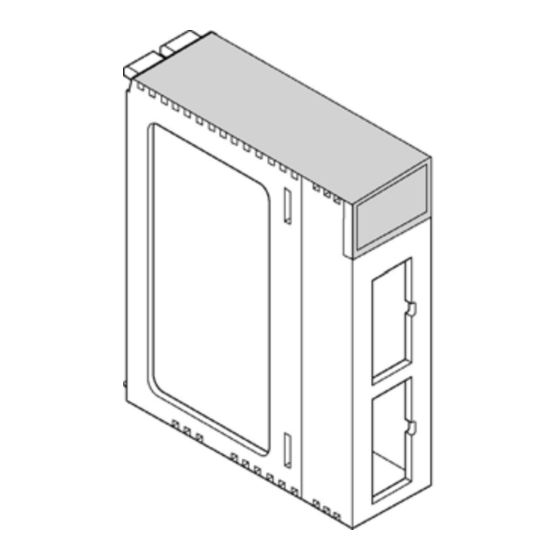
Page 140: Dimensions
10.1 Dimensions 10.1.1 FP2 Multi Communication Unit When one AFP2803 or AFP2804 is installed. When one AFP2805 is installed. Installation space in the panel 10-2... -
Page 141: Communication Blocks
10.1.2 Communication Blocks FP2-CB232 (AFP2803) FP2-CB422 (AFP2804) FP2-CB485 (AFP2805) 10-3... - Page 142 10-4...
- Page 143 Record of changes Manual No. Date Desceiption of changes ARCT1F396E 2004.SEP First edition ARCT1F396E-1 2004.SEP Second edition...
- Page 144 Automation Controls Company K Head Office: 1048, Kadoma, Kadoma-shi, Osaka 571-8686, Japan K Telephone: +81-6-6908-1050 K Facsimile: +81-6-6908-5781 http://www.nais-e.com/ All Rights Reserved © 2004 COPYRIGHT Matsushita Electric Works, Ltd. ARCT1F396E-1 200409 Specifications are subject to change without notice. Printed in Japan.