Table of Contents
Advertisement
Quick Links
Advertisement
Table of Contents

Related Manuals for Asus H610M-IM-A


Summary of Contents for Asus H610M-IM-A
- Page 1 H610M-IM-A...
- Page 2 Product warranty or service will not be extended if: (1) the product is repaired, modified or altered, unless such repair, modification of alteration is authorized in writing by ASUS; or (2) the serial number of the product is defaced or missing.
-
Page 3: Table Of Contents
Contents Chapter 1 Product overview Package contents................. 1-1 Features ..................1-1 Specifications ................1-2 Chapter 2 Motherboard information Before you proceed ..............2-1 Motherboard layout ..............2-2 Central Processing Unit (CPU) ........... 2-4 2.3.1 Installing the CPU ............2-5 2.3.2 CPU heatsink and fan assembly installation .... - Page 4 3.3.13 APM Configuration ............3-11 3.3.14 EzFlash ................. 3-12 3.3.14 Watchdog Timer ............3-12 Hardware Monitor menu ............3-13 Security menu ................3-13 Boot menu .................. 3-15 Exit menu ..................3-16 Save Changes & Exit ..............3-16 Discard Changes & Exit ............... 3-16 Save Changes &...
-
Page 5: Chapter 1 Product Overview
Chapter 1 Product overview Package contents Check your industrial motherboard package for the following items. 1 x ASUS H610M-IM-A Industrial Motherboard 1 x SATA 6.0 Gb/s cable 2 x M.2 screw package 1 x ASUS I/O Shield NOTE: If any of the above items is damaged or missing, contact your distributor or sales representative immediately. -
Page 6: Specifications
2 x COM ports (RS232/422/485) 2 x Audio jacks 4 x COM headers (RS232) Internal I/O 2 x USB 2.0 headers support additional 4 USB 2.0 ports connectors 1 x USB 2.0 Xstick connector (continued on the next page) H610M-IM-A... - Page 7 1 x CPU Fan header (PWM mode) 1 x Chassis Fan header (PWM mode) 1 x Chassis intrusion header 1 x Front Panel Audio header (AAFP) 1 x System Panel header 1 x Clear CMOS header 1 x Speaker header Internal I/O connectors 1 x GPIO header (8-bit)
- Page 8 H610M-IM-A...
-
Page 9: Chapter 2 Motherboard Information
Chapter 2 Motherboard information Before you proceed Take note of the following precautions before you install motherboard components or change any motherboard settings. CAUTION! • Unplug the power cord from the wall socket before touching any component. • Before handling components, use a grounded wrist strap or touch a safely grounded object or a metal object, such as the power supply case, to avoid damaging them due to static electricity. -
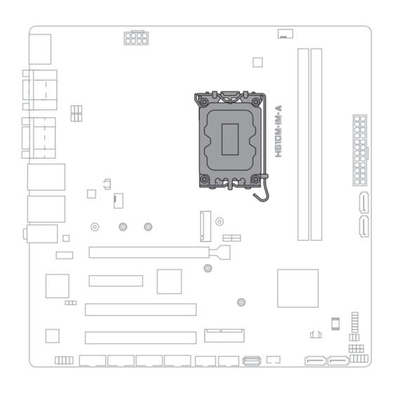
Page 10: Motherboard Layout
PCIE SATA 3.0 X4 PCIEX16(G5) GPIO_CON PCIEX4(G3) Super 1083 Intel ® H610 PCI_1 1 10 128Mb BIOS PCI_2 MPCIE SPEAKER 1 11 CHASSIS COM3 COM4 COM5 COM6 AAFP USB_56 USB_78 USB_9 SATA6G_4 SATA6G_3 KBMS_CON F_PANEL 15 14 13 12 H610M-IM-A... - Page 11 Connectors/Jumpers/Slots Page COM RING/+5V/+12V selection (COM1/2_SEL) 2-12 RTC Battery header (2-pin BATT_CON) 2-15 ATX Power connectors (24-pin EATXPWR, 8-pin ATX12V) 2-15 CPU and chassis fan headers (4-pin CPU_FAN, 4-pin CHA_FAN) 2-16 M.2 slot (SOCKET 3) 2-16 Intel LGA1700 CPU socket ®...
-
Page 12: Central Processing Unit (Cpu)
ASUS will shoulder the cost of repair only if the damage is shipment/transit-related. • Keep the cap after installing the motherboard. ASUS will process Return Merchandise Authorization (RMA) requests only if the motherboard comes with the cap on the LGA1700 socket. -
Page 13: Installing The Cpu
DO NOT install a CPU designed for LGA1155, LGA1156, LGA1151, and LGA1200 sockets on the LGA1700 socket. • ASUS will not cover damages resulting from incorrect CPU installation/ removal, incorrect CPU orientation/placement, or other damages resulting from negligence by the user. - Page 14 H610M-IM-A...
-
Page 15: Cpu Heatsink And Fan Assembly Installation
2.3.2 CPU heatsink and fan assembly installation CAUTION! Apply the Thermal Interface Material to the CPU heatsink and CPU before you install the heatsink and fan if necessary. To install the CPU heatsink and fan assembly Chapter 2: Motherboard information... - Page 16 Intel 600 series ® motherboard. • Additional holes for LGA1200 compatible cooling systems are also available on ASUS’ Intel 600 series motherboards, ® however, we still strongly advise consulting with your cooling system vendor or manufacturer on the...
-
Page 17: System Memory
System memory This motherboard comes with two Double Data Rate 4 (DDR4) Dual Inline Memory Module (DIMM) sockets. The figure below illustrates the location of the DDR4 DIMM sockets: Channel Sockets Channel A DIMM_A Channel B DIMM_B Installing a DIMM Chapter 2: Motherboard information... - Page 18 To remove a DIMM H610M-IM-A 2-10...
-
Page 19: Jumpers
Jumpers Clear RTC RAM (2-pin CLRTC) This header allows you to clear the CMOS RTC RAM data of the system setup information such as date, time, and system passwords. CLRTC PIN 1 HEADER 1x2p, 2.54mm pitch, S/T Connector type To erase the RTC RAM: Turn OFF the computer and unplug the power cord. - Page 20 COM Ring/+5V/+12V selection jumper (6-pin COM1/2_SEL) COM1_SEL COM2_SEL +12V (Default) Setting Pins +12V Ring (Default) AT/ATX mode selection (3-pin AT_ATX_SEL) AT_ATX_SEL ATX mode AT mode (Default) Pins 1-2 (Default) ATX mode AT mode Connector type HEADER 1x3p, 2.54mm pitch, S/T H610M-IM-A 2-12...
-
Page 21: Connectors
Connectors 2.6.1 Rear panel connectors DisplayPort. This port is for a DisplayPort-compatible device. Video Graphics Adapter (VGA) port. This 15-pin port is for a VGA monitor or other VGA-compatible devices. COM ports (COM, RS232/RS422/RS485). These ports connect modems, or other devices that conform with serial specification. LAN (RJ-45) ports. - Page 22 Pink (Rear panel) Mic In Mic In Bass/Center Bass/Center Lime (Front panel) Side Speaker Out To configure a 7.1-channel audio output: Use a chassis with HD audio module in the front panel to support a 7.1-channel audio output. H610M-IM-A 2-14...
-
Page 23: Internal Connectors
2.6.2 Internal connectors Battery header (2-pin BATTERY) This header is for the lithium CMOS battery. BATT_CON +BAT PIN 1 ATX Power connectors (24-pin EATXPWR, 8-pin ATX12V) Correctly orient the ATX power supply plugs into these connectors and push down firmly until the connectors completely fit. EATX12V ATX_PWR +3 Volts... - Page 24 These are not jumpers! Do not place jumper caps on the fan headers! M.2 slot (SOCKET 3) This slot allows you to install an M.2 SSD module. M.2(SOCKET3) NOTES: • The M.2 SSD module is purchased separately. • This slot supports M Key and 2242/2260/2280 storage devices. H610M-IM-A 2-16...
- Page 25 SATA 6.0Gb/s ports (7-pin SATA6G_1-4) These ports connect to SATA 6.0 Gb/s hard disk drives or an optical drive via SATA 6.0 Gb/s signal cables. SATA6G_1 SATA6G_2 RSATA_TXP RSATA_TXN RSATA_RXN RSATA_RXP SATA6G_3 SATA6G_4 TPM header (14-1 pin TPM) This header supports a Trusted Platform Module (TPM) system with a Serial Peripheral Interface (SPI), allowing you to securely store keys, digital certificates, passwords and data.
- Page 26 Header 2x3p, K6, 2.0mm pitch Speaker header (4-pin SPEAKER) The 4-pin header is for the chassis-mounted system warning speaker. The speaker allows you to hear system beeps and warnings. SPEAKER PIN 1 HEADER 1x4p, 2.54mm pitch, S/T Connector type H610M-IM-A 2-18...
- Page 27 Chassis Intrusion header (4-1 pin_CHASSIS) This header is for a chassis-mounted intrusion detection sensor or switch. Connect one end of the chassis intrusion sensor or switch cable to this connector. The chassis intrusion sensor or switch sends a low-level signal to this connector when a chassis component is installed.
- Page 28 ATX power button/soft-off button (2-pin PWR_BTN) This 2-pin header is for the system power button. • Reset button (2-pin RESET) This 2-pin header is for the chassis-mounted reset button for system reboot without turning off the system power. H610M-IM-A 2-20...
- Page 29 11. MPCIE slot This slot allows you to install a full length mini-PCIe card, providing you with expandability and connectivity solutions for an optimal system performance. MPCIE PIN 1 12. PS/2 Keyboard & Mouse header (8-pin KBMS_CON) This header is for an IBM PS/2-compatible keyboard or mouse. KBMS_CON PIN 1 Chapter 2: Motherboard information...
- Page 30 COM3 COM4 COM5 PIN 1 COM6 Header 2x5p, K10, 2.54mm pitch Connector type NOTE: The serial port cable is purchased separately. H610M-IM-A 2-22...
- Page 31 15. Front Panel Audio header (10-1 pin AAFP) This header is for a chassis-mounted front panel audio I/O module that supports HD Audio standard. Connect one end of the front panel audio I/O module cable to this header. AAFP PIN 1 Connector type HEADER 2x5p, K8, 2.54mm pitch IMPORTANT!
- Page 32 H610M-IM-A 2-24...
-
Page 33: Chapter 3 Bios Setup
Always shut down the system properly from the operating system. IMPORTANT: • Visit the ASUS website at www.asus.com to download the latest BIOS file for this motherboard. • The default BIOS settings for this motherboard apply to most working conditions and ensures optimal performance. -
Page 34: Bios Menu Screen
The Main menu provides you an overview of the basic system information, and allows you to set the system date, time, language, and security settings. 3.2.1 System Date [Day MM/DD/YYYY] Allows you to set the system date. 3.2.2 System Time [HH:MM:SS] Allows you to set the system time. H610M-IM-A... -
Page 35: Advanced Menu
Advanced menu The Advanced menu items allow you to change the settings for the CPU and other system devices. Be cautious when changing the settings of the Advanced menu items. Incorrect field values can cause the system to malfunction. 3.3.1 PCH-FW Configuration TPM Device Selection This item allows you to select the TPM device. -
Page 36: Cpu Configuration
P-state. Configuration options: [Disabled] [Enabled] Turbo Mode This item allows you to enable or disable Turbo Mode for your processor. Configuration options: [Enabled] [Disabled] CPU C states [Enabled] Enables the CPU C states. [Disabled] Disables the CPU C states. H610M-IM-A... -
Page 37: Graphics Configuration
Enhanced C-states [Disabled] Disables enhanced C1 state. [Enabled] Enables enhanced C1 state. Power Limit 1 Override [Disabled] Disables power limit 1. [Enabled] Enables power limit 1. Power Limit 2 Override [Disabled] Disables power limit 2. [Enabled] Enables power limit 2. Power Limit 2 This item allows you to input the value of power limit 2 in milliwatts. -
Page 38: Super Io Configuration
Express device. Configuration options: [Disabled] [Enabled] 3.3.6 Super IO Configuration Super IO Configuration Serial Port 1 Configuration Serial Port Allows you to enable or disable the serial port (COM).Configuration options: [Disabled] [Enabled] The following items appear only when you set Serial Port to [Enabled]. H610M-IM-A... -
Page 39: Serial Console Configuration
COM1 Control Allows you to select the COM1 mode. Configuration options: [RS232] [RS422] [RS485] Serial Port 2 Configuration Serial Port Allows you to enable or disable the serial port (COM).Configuration options: [Disabled] [Enabled] The following item appears only when you set Serial Port to [Enabled]. COM2 Control Allows you to select the COM2 mode. - Page 40 Allows you to enable or disable VT-UTF8 Combination Key Support for ANSI/ VT100 terminals. Configuration options: [Disabled] [Enabled] Recorder Mode With this mode enabled only text will be sent. This is to capture Terminal data. Configuration options: [Disabled] [Enabled] H610M-IM-A...
-
Page 41: Sata Configuration
Resolution 100x31 Allows you to enable or disable extended terminal resolution. Configuration options: [Disabled] [Enabled] Putty KeyPad Allows you to select FunctionKey and KeyPad on Putty. Configuration options: [VT100] [LINUX] [XTERMR6] [SCO] [ESCN] [VT400] 3.3.8 SATA Configuration This item allows you to configure SATA device options settings. SATA Controller(s) Allows you to enables or disables the onboard SATA device. -
Page 42: Network Stack Configuration
BIOS or OS. Configuration options: [Disabled] [Enabled] U32G1_3/4 Allows you to enable or disable the USB port. Once set to [Disabled], any USB devices plugged into the connector will not be detected by BIOS or OS. Configuration options: [Disabled] [Enabled] H610M-IM-A 3-10... -
Page 43: Nvme Configuration
USB5-10 Allows you to enable or disable USB port. Once set to [Disabled], any USB devices plugged into the connector will not be detected by BIOS or OS. Configuration options: [Disabled] [Enabled] 3.3.11 NVMe Configuration The NVMe Configuration menu displays the NVMe controller and drive information of the devices connected and allows you to configure NVMe device options settings. -
Page 44: Ezflash
Allows you to select Watchdog Timer I count mode. Configuration options: [Second Mode] [Minute Mode] Watchdog Timer Use the <+> and <-> keys to adjust the value or input the desired value directly. The value ranges from 1 to 255. H610M-IM-A 3-12... -
Page 45: Hardware Monitor Menu
Hardware Monitor menu The items in this menu provide you an overview of system status including temperature, fan speed and voltage, and allow you to configure the smart fan. Smart Fan Mode Allows you to select the smart fan mode. Configuration options: [Disabled] [Normal] [Manual Mode] The following item appears only when you set Smart Fan Mode to [Manual Mode]. - Page 46 Configuration options: [Standard] [Custom] Key Management The Key Management item allows you to modify Secure Boot variables and set Key Management page. Platform Key (PK) / Key Exchange Keys / Authorized Signatures / Forbidden Signatures Configuration options: [Update] [Append] H610M-IM-A 3-14...
-
Page 47: Boot Menu
Boot menu The Boot menu items allow you to change the system boot options. Boot Configuration CHASSIS INTRUDE Allows you to enable or disable the chassis intrusion detection function. Configuration options: [Disabled] [Enabled] Setup Prompt Timeout Allows you to set the number of seconds to wait for setup activation key. 65535(0xFFFF) means indefinite waiting. -
Page 48: Save Changes & Reset
Restore/load default values for all the setup options. Save as User Defaults This option allows you to save the changes you have made so far as user defaults. Restore User Defaults Restore the user defaults with all the setup options. H610M-IM-A 3-16... -
Page 49: Appendix
Appendix Notices FCC Compliance Information Responsible Party: Asus Computer International Address: 48720 Kato Rd., Fremont, CA 94538, USA Phone / Fax No: (510)739-3777 / (510)608-4555 This device complies with part 15 of the FCC Rules. Operation is subject to the following two conditions: (1) This device may not cause harmful interference, and (2) this device must accept any interference received, including interference that may cause undesired operation. - Page 50 CAN ICES-003(B)/NMB-003(B) VCCI: Japan Compliance Statement Class B ITE KC: Korea Warning Statement HDMI Compliance Statement The terms HDMI, HDMI High-Definition Multimedia Interface, and the HDMI Logo are trademarks or registered trademarks of HDMI Licensing Administrator, Inc. H610M-IM-A...
- Page 51 ASUS Recycling/Takeback Services ASUS recycling and takeback programs come from our commitment to the highest standards for protecting our environment. We believe in providing solutions for you to be able to responsibly recycle our products, batteries, other components as well as the packaging materials.
- Page 52 доступний на: www.asus.com/support Cijeli tekst EU izjave o sukladnosti dostupan je na: www.asus.com/support Türkçe AsusTek Computer Inc., bu aygıtın temel gereksinimlerle ve ilişkili Čeština Společnost ASUSTeK Computer Inc. tímto prohlašuje, že toto Yönergelerin diğer ilgili koşullarıyla uyumlu olduğunu beyan eder.
-
Page 53: Service And Support
Service and Support Visit our multi-language website at https://www.asus.com/support/ Appendix...