Table of Contents
Advertisement
Quick Links
I86PE-A4 Setup Manual
FCC Information and Copyright
This equipment has been tested and found to comply with the limits of a Class
B digital device, pursuant to Part 15 of the FCC Rules. These limits are designed
to provide reasonable protection against harmful interference in a residential
installation. This equipment generates, uses and can radiate radio frequency
energy and, if not installed and used in accordance with the instructions, may
cause harmful interference to radio communications. There is no guarantee
that interference will not occur in a particular installation.
The vendor makes no representations or warranties with respect to the
contents here and specially disclaims any implied warranties of merchantability
or fitness for any purpose. Further the vendor reserves the right to revise this
publication and to make changes to the contents here without obligation to
notify any party beforehand.
Duplication of this publication, in part or in whole, is not allowed without first
obtaining the vendor's approval in writing.
The content of this user's manual is subject to be changed without notice and
we will not be responsible for any mistakes found in this user's manual. All the
brand and product names are trademarks of their respective companies.
Advertisement
Chapters
Table of Contents

Related Manuals for Biostar I86PE-A4


Summary of Contents for Biostar I86PE-A4
- Page 1 I86PE-A4 Setup Manual FCC Information and Copyright This equipment has been tested and found to comply with the limits of a Class B digital device, pursuant to Part 15 of the FCC Rules. These limits are designed to provide reasonable protection against harmful interference in a residential installation.
-
Page 2: Table Of Contents
Table of Contents Chapter 1: Introduction.......... 3 Before You Start ................3 Package Checklist................3 Motherboard Features..............4 Rear Panel Connectors ..............5 Motherboard Layout (Ver 1.0) ............6 Motherboard Layout (Ver 7.0)............7 Chapter 2: Hardware Installation ......7 Installing Central Processing Unit (CPU)........8 FAN Headers..................9 Installing System Memory ..............10 Connectors and Slots ...............11 Chapter 3: Headers &... -
Page 3: Chapter 1: Introduction
I86PE-A4 CHAPTER 1: INTRODUCTION EFORE TART Thank you for choosing our product. Before you start installing the motherboard, please make sure you follow the instructions below: Prepare a dry and stable working environment with sufficient lighting. Always disconnect the computer from power outlet before operation. - Page 4 Motherboard Manual OTHERBOARD EATURES Ver 1.0 Ver 7.0 Socket 478 Socket 478 Intel Northwood / Prescott processor up to Intel Northwood / Prescott processor up to 3.4 GHz 3.4 GHz Supports Hyper-Threading Technology Supports Hyper-Threading Technology 400 / 533 / 800 MHz 400 / 533 / 800 MHz Intel 865PE Intel 865PE...
- Page 5 Board Size 225 (W) x 294 (L) mm 225 (W) x 294 (L) mm Windows 2K / XP Windows 2K / XP Biostar Reserves the right to add or remove Biostar Reserves the right to add or remove Support support for any OS with or without notice.
-
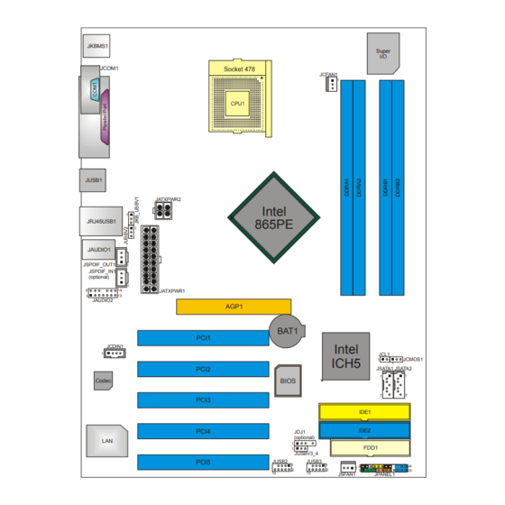
Page 6: Motherboard Layout (Ver 1.0)
Motherboard Manual 1.0) OTHERBOARD AYOUT JKBMS1 Super JCOM1 JCFAN1 JUSB1 JATXPWR2 Intel 865PE JRJ45USB1 JAUDIO1 JSPDIF_OUT1 JSPDIF_IN1 (optional) JATXPWR1 JAUDIO2 AGP1 BAT1 PCI1 Intel JCDIN1 JCL1 ICH5 JCMOS1 PCI2 JSATA1 JSATA2 BIOS Codec PCI3 IDE1 IDE2 PCI4 JDJ1 (optional) FDD1 JUSBV3_4 PCI5 JUSB2... -
Page 7: Motherboard Layout (Ver 7.0)
I86PE-A4 7.0) OTHERBOARD AYOUT JKBMS1 Super JCOM1 JCFAN1 JUSB1 JATXPWR2 Intel 865PE JRJ45USB1 JAUDIO1 JSPDIF_OUT1 JSPDIF_IN1 (optional) JATXPWR1 JAUDIO2 AGP1 BAT1 PCI1 Intel JCDIN1 JCL1 (optional) ICH5 JCMOS1 PCI2 JSATA1 JSATA2 BIOS Codec PCI3 IDE1 IDE2 PCI4 JDJ1 (optional) FDD1... -
Page 8: Installing Central Processing Unit (Cpu)
Motherboard Manual (CPU) NSTALLING ENTRAL ROCESSING Step 1: Pull the lever sideways away from the socket and then raise the lever up to a 90-degree angle. Step 2: Look for the white dot/cut edge. The white dot/cut edge should point wards the lever pivot. The CPU will fit only in the correct orientation. -
Page 9: Fan Headers
I86PE-A4 FAN H EADERS These fan headers support cooling-fans built in the computer. The fan cable and connector may be different according to the fan manufacturer. Connect the fan cable to the connector while matching the black wire to pin#1. -
Page 10: Installing System Memory
Motherboard Manual NSTALLING YSTEM EMORY Unlock a DIMM slot by pressing the retaining clips outward. Align a DIMM on the slot such that the notch on the DIMM matches the break on the Slot. Insert the DIMM vertically and firmly into the slot until the retaining chip snap back in place and the DIMM is properly seated. -
Page 11: Connectors And Slots
I86PE-A4 ONNECTORS AND LOTS FDD1: Floppy Disk Connector The motherboard provides a standard floppy disk connector that supports 360K, 720K, 1.2M, 1.44M and 2.88M floppy disk types. This connector supports the provided floppy drive ribbon cables. IDE1/IDE2: Hard Disk Connectors The motherboard has a 32-bit Enhanced PCI IDE Controller that provides PIO Mode 0~4, Bus Master, and Ultra DMA 33/66/100 functionality. - Page 12 Motherboard Manual PCI1~PCI5: Peripheral Component Interconnect Slots This motherboard is equipped with 5 standard PCI slots. PCI stands for Peripheral Component Interconnect, and it is a bus standard for expansion cards. This PCI slot is designated as 32 bits. AGP1: Accelerated Graphics Port Slot Your monitor will attach directly to that video card.
-
Page 13: Chapter 3: Headers & Jumpers Setup
I86PE-A4 CHAPTER 3: HEADERS & JUMPERS SETUP OW TO ETUP UMPERS The illustration shows how to set up jumpers. When the jumper cap is placed on pins, the jumper is “close”, if not, that means the jumper is “open”. Pin opened... - Page 14 Motherboard Manual JPANEL1: Front Panel Header (for Ver 7.0) This 24-pin connector includes Power-on, Reset, HDD LED, Power LED, Sleep button, speaker and IrDA Connection. It allows user to connect the PC case’s front panel switch functions. IR(optional) PW R_LED On/Off Assignment Function...
- Page 15 I86PE-A4 JATXPWR2: ATX Power Source Connector By connecting this connector, it will provide +12V to CPU power circuit. Assignment +12V +12V Ground Ground...
- Page 16 Motherboard Manual JUSB2/JUSB3: Headers for 2.0 Ports at Front USB Panel This motherboard provides 2 USB 2.0 headers, which allows user to connect additional USB cable on the PC front panel, and also can be connected with internal USB devices, like USB card reader. Assignment +5V (fused) +5V (fused)
- Page 17 I86PE-A4 JFAUDIO1: Front Panel Audio Header This header allows user to connect the front audio output cable with the PC front panel. It will disable the output on back panel audio connectors. Assignment Mic in/center Ground Mic power/Bass Audio power...
- Page 18 Motherboard Manual JCMOS1: Clear CMOS Header By placing the jumper on pin2-3, it allows user to restore the BIOS safe setting and the CMOS data, please carefully follow the procedures to avoid damaging the motherboard. Pin 1-2 Close: Normal Operation (default). Pin 2-3 Close: Clear CMOS data.
- Page 19 I86PE-A4 JSATA1~JSATA2: Serial ATA Connectors The motherboard has a PCI to SATA Controller with 2 channels SATA interface, it satisfies the SATA 1.0 spec and with transfer rate of 1.5Gb/s. Assignment Ground Ground Ground JSPDIF_OUT1 (optional)/ JSPDIF_IN1 (optional): Digital Audio-out Connector This connector allows user to connect the PCI bracket SPDIF output header.
-
Page 20: Chapter 4: Useful Help
Motherboard Manual CHAPTER 4: USEFUL HELP RIVER NSTALLATION After you installed your operating system, please insert the Fully Setup Driver CD into your optical drive and install the driver for better system performance. You will see the following window after you insert the CD The setup guide will auto detect your motherboard and operating system. -
Page 21: Award Bios Beep Code
BIOS contents are corrupted. In this Case, please follow the procedure below to restore the BIOS: 1. Make a bootable floppy disk. 2. Download the Flash Utility “AWDFLASH.exe” from the Biostar website: www.biostar.com.tw 3. Confirm motherboard model and download the respectively BIOS from Biostar website. - Page 22 Motherboard Manual B. CPU Overheated If the system shutdown automatically after power on system for seconds, that means the CPU protection function has been activated. When the CPU is over heated, the motherboard will shutdown automatically to avoid a damage of the CPU, and the system may not power on again.
-
Page 23: Troubleshooting
I86PE-A4 4.4 T ROUBLESHOOTING Probable Solution No power to the system at all Make sure power cable is Power light don’t illuminate, fan securely plugged in. inside power supply does not turn Replace cable. Contact technical support. Indicator light on keyboard does not turn on. -
Page 24: Chapter 5: Warpspeeder
Motherboard Manual WARPSPEEDER™ CHAPTER 5: NTRODUCTION [WarpSpeeder™], a new powerful control utility, features three user-friendly functions including Overclock Manager, Overvoltage Manager, and Hardware Monitor. With the Overclock Manager, users can easily adjust the frequency they prefer or they can get the best CPU performance with just one click. The Overvoltage Manager, on the other hand, helps to power up CPU core voltage and Memory voltage. -
Page 25: Installation
I86PE-A4 NSTALLATION 1. Execute the setup execution file, and then the following dialog will pop up. Please click “Next” button and follow the default procedure to install. 2. When you see the following dialog in setup procedure, it means setup is completed. -
Page 26: Warpspeeder
Motherboard Manual ™ PEEDER 1. Tray Icon: Whenever the Tray Icon utility is launched, it will display a little tray icon on the right side of Windows Taskbar. This utility is responsible for conveniently invoking [WarpSpeeder™] Utility. You can use the mouse by clicking the left button in order to invoke [WarpSpeeder™] directly from the little tray icon or you can right-click the little tray icon to pop up a popup menu as following figure. - Page 27 I86PE-A4 2. Main Panel If you click the tray icon, [WarpSpeeder™] utility will be invoked. Please refer to the following figure; the utility’s first window you will see is Main Panel. Main Panel contains features as follows: a. Display the CPU Speed, CPU external clock, Memory clock, AGP clock, and PCI clock information.
- Page 28 Motherboard Manual 3. Voltage Panel Click the Voltage button in Main Panel, the button will be highlighted and the Voltage Panel will slide out to up as the following figure. In this panel, you can decide to increase CPU core voltage and Memory voltage or not.
- Page 29 I86PE-A4 4. Overclock Panel Click the Overclock button in Main Panel, the button will be highlighted and the Overclock Panel will slide out to left as the following figure. Overclock Panel contains the these features: a. “–3MHz button”, “-1MHz button”, “+1MHz button”, and “+3MHz button”: provide user the ability to do real-time overclock adjustment.
- Page 30 Motherboard Manual “Auto-overclock button”: User can click this button and [WarpSpeeder™] will set the best and stable performance and frequency automatically. [WarpSpeeder™] utility will execute a series of testing until system fail. Then system will do fail-safe reboot by using Watchdog function. After reboot, the [WarpSpeeder™] utility will restore to the hardware default setting or load the verified best and stable frequency according to the Recovery Dialog’s setting.
- Page 31 I86PE-A4 6. About Panel Click the “about” button in Main Panel, the button will be highlighted and the About Panel will slide out to up as the following figure. In this panel, you can get model name and detail information in hints of all the chipset that are related to overclocking.
-
Page 32: Appendencies: Spec In Other Language
Motherboard Manual APPENDENCIES: SPEC IN OTHER LANGUAGE ERMAN Ver 1.0 Ver 7.0 Sockel 478 Sockel 478 Intel Northwood / Prescott Prozessoren mit Intel Northwood / Prescott Prozessoren mit bis zu 3,4 GHz bis zu 3,4 GHz Unterstützt die Unterstützt die Hyper-Threading-Technologie Hyper-Threading-Technologie 400/ 533 / 800 MHz... - Page 33 225 mm (B) X 294 mm (L) ße. Windows 2K / XP Windows 2K / XP Biostar behält sich das Recht vor, ohne Biostar behält sich das Recht vor, ohne OS-Unterst Ankündigung die Unterstützung für ein Ankündigung die Unterstützung für ein ützung...
-
Page 34: France
Motherboard Manual RANCE Ver 1.0 & Ver 7.0 Ver 7.1 Socket 478 Socket 478 Processeurs Intel Northwood / Prescott Processeurs Intel Northwood / Prescott jusqu'à 3,4 GHz jusqu'à 3,4 GHz Prend en charge la technologie Prend en charge la technologie Hyper-Threading Hyper-Threading Bus frontal 400/ 533 / 800 MHz... - Page 35 Windows 2K / XP Windows 2K / XP Support Biostar se réserve le droit d'ajouter ou de Biostar se réserve le droit d'ajouter ou de supprimer le support de SE avec ou sans supprimer le support de SE avec ou sans préavis.
-
Page 36: Italian
Motherboard Manual TALIAN Ver 1.0 Ver 7.0 Socket 478 Socket 478 Processore Intel Northwood / Prescott fino a Processore Intel Northwood / Prescott fino a 3.4 GHz 3.4 GHz Supporto tecnologia Hyper-Threading Supporto tecnologia Hyper-Threading 400/ 533 / 800 MHz 400/ 533 / 800 MHz Intel 865PE Intel 865PE... - Page 37 Windows 2K / XP Windows 2K / XP Sistemi Biostar si riserva il diritto di aggiungere o Biostar si riserva il diritto di aggiungere o operativi rimuovere il supporto di qualsiasi sistema rimuovere il supporto di qualsiasi sistema supportati operativo senza preavviso.
-
Page 38: Spanish
Motherboard Manual PANISH Ver 1.0 Ver 7.0 Conector 478 Conector 478 Procesador Intel Northwood / Prescott Procesador Intel Northwood / Prescott hasta 3,4 GHz hasta 3,4 GHz Soporta tecnología Hyper-Threading Soporta tecnología Hyper-Threading 400 / 533 / 800 MHz 400 / 533 / 800 MHz Conjunto Intel 865PE Intel 865PE... - Page 39 Windows 2K / XP Windows 2K / XP Soporte de Biostar se reserva el derecho de añadir o Biostar se reserva el derecho de añadir o sistema retirar el soporte de cualquier SO con o sin retirar el soporte de cualquier SO con o sin operativo aviso previo.
-
Page 40: Portuguese
Motherboard Manual ORTUGUESE Ver 1.0 Ver 7.0 Socket 478 Socket 478 Processador Intel Northwood / Prescott até Processador Intel Northwood / Prescott até 3,4 GHz 3,4 GHz Suporta a tecnologia Hyper-Threading Suporta a tecnologia Hyper-Threading 400/ 533 / 800 MHz 400/ 533 / 800 MHz Intel 865PE Intel 865PE... - Page 41 Sistemas Windows 2K / XP Windows 2K / XP operativos A Biostar reserva-se o direito de adicionar A Biostar reserva-se o direito de adicionar suportado ou remover suporte para qualquer sistema ou remover suporte para qualquer sistema operativo com ou sem aviso prévio.
-
Page 42: Polish
Motherboard Manual OLISH Ver 1.0 Ver 7.0 Socket 478 Socket 478 Procesor Intel Northwood / Prescott do 3,4 Procesor Intel Northwood / Prescott do 3,4 Procesor Obsługa technologii Hyper-Threading Obsługa technologii Hyper-Threading 400/ 533 / 800 MHz 400/ 533 / 800 MHz Intel 865PE Intel 865PE Chipset... - Page 43 225 mm (S) X 294 mm (W) płyty Obsluga Windows 2K / XP Windows 2K / XP systemu Biostar zastrzega sobie prawo dodawania Biostar zastrzega sobie prawo dodawania operacyjn lub odwoływania obsługi dowolnego lub odwoływania obsługi dowolnego systemu operacyjnego bez powiadomienia.
-
Page 44: Russian
Motherboard Manual RUSSIAN Ver 1.0 Ver 7.0 Гнездо 478 Гнездо 478 (централь Процессор Intel Northwood / Prescott до Процессор Intel Northwood / Prescott до ный 3.4 ГГц 3.4 ГГц процессор Поддержка технологии Hyper-Threading Поддержка технологии Hyper-Threading 400/ 533 / 800 МГц 400/ 533 / 800 МГц... - Page 45 225 мм (Ш) X 294 мм (В) 225 мм (Ш) X 294 мм (В) панели Windows 2K / XP Windows 2K / XP Biostar сохраняет за собой право Biostar сохраняет за собой право Поддержк добавлять или удалять средства добавлять или удалять средства...
-
Page 46: Arabic
Motherboard Manual ARABIC Ver 7.0 Ver 1.0 874ﻡﻘﺒﺲ 874ﻡﻘﺒﺲ ﻡﻌﺎﻟﺠﺎتIntel Northwood / Prescott ﺏﺴﺮﻋﺔ ﺗﺼﻞ ﻡﻌﺎﻟﺠﺎتIntel Northwood / Prescott ﺏﺴﺮﻋﺔ ﺗﺼﻞ اﻟﻤﻌﺎﻟﺠﺔ وﺣﺪة ﺝﻴﺠﺎ هﺮﺗﺰ إﻟﻰ ﺝﻴﺠﺎ هﺮﺗﺰ إﻟﻰ اﻟﻤﺮآﺰﻳﺔ ﺗﺪﻋﻢ ﺗﻘﻨﻴﺔHyper-Threading ﺗﺪﻋﻢ ﺗﻘﻨﻴﺔHyper-Threading اﻷﻣﺎﻣﻲ ﻗﻞ اﻟﻨﺎ ﻡﻴﺠﺎ هﺮﺗﺰ 008 / 335 /004 ﺗﺮدد ﻡﻴﺠﺎ... - Page 47 I86PE-A4 Ver 7.0 Ver 1.0 ﻋﺪد ﻡﻨﻔﺬ اﻟﺼﻮت اﻷﻡﺎﻡﻲ ﻋﺪد ﻡﻨﻔﺬ اﻟﺼﻮت اﻷﻡﺎﻡﻲ ﻋﺪد CD-IN ﻡﻨﻔﺬ ﻋﺪد CD-IN ﻡﻨﻔﺬ ﻋﺪد اﺧﺘﻴﺎري S/PDIF ﻡﻨﻔﺬ دﺧﻞ ﻋﺪد اﺧﺘﻴﺎري S/PDIF ﻡﻨﻔﺬ دﺧﻞ ﻋﺪد S/PDIF ﻡﻨﻔﺬ ﺧﺮج ﻋﺪد S/PDIF ﻡﻨﻔﺬ ﺧﺮج ﻋﺪد وﺹﻠﺔ ﻡﺮوﺣﺔ وﺣﺪة اﻟﻤﻌﺎﻟﺠﺔ اﻟﻤﺮآﺰﻳﺔ...
-
Page 48: Japanese
Motherboard Manual JAPANESE Ver 1.0 Ver 7.0 Socket 478 Socket 478 最大3.4 GHzのIntel Northwood / Prescottプ 最大3.4 GHzのIntel Northwood / Prescottプ ロセッサ ロセッサ ハイパースレッドテクノロジをサポートします ハイパースレッドテクノロジをサポートします 400/ 533 / 800 MHz 400/ 533 / 800 MHz Intel 865PE Intel 865PE チップセッ Intel ICH5 Intel ICH5 ト... - Page 49 I86PE-A4 Ver 1.0 Ver 7.0 S/PDIFアウトコネクタ S/PDIFアウトコネクタ CPUファンヘッダ CPUファンヘッダ システムファンヘッダ システムファンヘッダ シャーシオープンヘッダ(オプション) シャーシオープンヘッダ(オプション) CMOSクリアヘッダ CMOSクリアヘッダ USBコネクタ USBコネクタ 電源コネクタ(20ピン) 電源コネクタ(20ピン) 電源コネクタ(4ピン) 電源コネクタ(4ピン) PS/2キーボード PS/2キーボード PS/2マウス PS/2マウス シリアルポート シリアルポート 背面パネル プリンタポート プリンタポート LANポート LANポート USBポート USBポート オーディオジャック オーディオジャック ボードサイ 225 mm (幅) X 294 mm (高さ) 225 mm (幅) X 294 mm (高さ)
- Page 50 Table of Contents BIOS Setup …………………………………………………………1 Main Menu ....................4 Standard CMOS Features................7 Advanced BIOS Features................9 Advanced Chipset Features ..............13 Integrated Peripherals................16 Power Management Setup ..............23 PnP/PCI Configurations ................. 28 PC Health Status..................31 Frequency Control..................32...
-
Page 51: Bios Setup
I86PE-A4 BIOS Setup BIOS SETUP Introduction This manual discussed Award™ Setup program built into the ROM BIOS. The Setup program allows users to modify the basic system configuration. This special information is then stored in battery-backed RAM so that it retains the Setup information when the power is turned off. - Page 52 I86PE-A4 BIOS Setup (Peripheral Component Interconnect) local bus specification.
- Page 53 I86PE-A4 BIOS Setup DRAM Support DDR DRAM (Double Data Rate Synchronous DRAM) are supported. Supported CPUs ® This AWARD BIOS supports the Intel Pentium 4 CPU. Using Setup In general, you use the arrow keys to highlight items, press <Enter> to select, use the <PgUp>...
-
Page 54: Main Menu
I86PE-A4 BIOS Setup Main Menu Once you enter Award BIOS™ CMOS Setup Utility, the Main Menu will appear on the screen. WARNING The information about BIOS defaults on manual (Figure 1,2,3,4,5,6,7,8,9) is just for reference; please refer to the BIOS installed on board, for update information. - Page 55 I86PE-A4 BIOS Setup P/PCI C ONFIGURATIONS This submenu allows you to configure certain “Plug and Play” and PCI options. PC H EALTH TATUS This submenu allows you to monitor the hardware of your system. REQUENCY ONTROL This submenu allows you to change CPU Vcore Voltage and CPU/PCI clock.
- Page 56 I86PE-A4 BIOS Setup 1.11 & E ETUP Save all configuration changes to CMOS(memory) and exit setup. Confirmation message will be displayed before proceeding. 1.12 ITHOUT AVING Abandon all changes made during the current session and exit setup. Confirmation message will be displayed before proceeding.
-
Page 57: Standard Cmos Features
I86PE-A4 BIOS Setup Standard CMOS Features The items in Standard CMOS Setup Menu are divided into 10 categories. Each category includes no, one or more than one setup items. Use the arrow keys to highlight the item and then use the<PgUp> or <PgDn> keys to select the value... - Page 58 I86PE-A4 BIOS Setup ELECTIONS This table shows the selections that you can make on the Main Menu. Item Options Description Date mm : dd : yy Set the system date. Note that the ‘Day’ automatically changes when you set the date.
-
Page 59: Advanced Bios Features
I86PE-A4 BIOS Setup Advanced BIOS Features & F LOPPY ETUP 3.1.1 First/ Second/ Third/ Boot Other Device These BIOS attempt to load the operating system from the device in the sequence selected in these items. The Choices: Floppy, LS120, HDD-0, SCSI, CDROM, HDD-1, HDD-2, HDD-3, ZIP100, LAN, HPT370, Disabled, Enabled. - Page 60 I86PE-A4 BIOS Setup ACHE ETUP CPU L1&L2 Cache Depending on the CPU/chipset in use, you may be able to increase memory access time with this option. Enabled (default) Enable cache. Disabled Disable cache. CPU F EATURE 3.3.1 Thermal Management This item allows you to choose the monitor’s thermal management.
- Page 61 I86PE-A4 BIOS Setup YPER HREADING ECHNOLOGY This option allows you to enable or disabled Hyper-Threading Technology. “Enabled” for Windows XP and Linux 2.4.x (OS optimized for Hyper-Threading Technology). “Disable” for other OS (OS not optimized for Hyper-Threading Technology). The Choices: Enabled (Default), Disabled.
- Page 62 I86PE-A4 BIOS Setup 3.11 YPEMATIC ELAY Sets the delay time after the key is held down before it begins to repeat the keystroke. The Choices: 250 (default), 500,750,1000. 3.12 ECURITY PTION This option will enable only individuals with passwords to bring the system online and/or to use the CMOS Setup Utility.
-
Page 63: Advanced Chipset Features
I86PE-A4 BIOS Setup Advanced Chipset Features This submenu allows you to configure the specific features of the chipset installed on your system. This chipset manage bus speeds and access to system memory resources, such as DRAM. It also coordinates communications with the PCI bus. The default settings that came with your system have been optimized and therefore should not be changed unless you are suspicious that the settings have been changed incorrectly. - Page 64 I86PE-A4 BIOS Setup DRAM RAS# CAS# D ELAY This field let you insert a timing delay between the CAS and RAS strobe signals, used when DRAM is written to, read from, or refreshed. Fast gives faster performance; and slow gives more stable performance. This field applies only when synchronous DRAM is installed in the system.
- Page 65 I86PE-A4 BIOS Setup 15M-16M EMORY You can reserve this area of system memory for ISA adapter ROM. When this area is reserved it cannot be cached. The user information of peripherals that need to use this area of system memory usually2 discussed their memory requirements.
-
Page 66: Integrated Peripherals
I86PE-A4 BIOS Setup Integrated Peripherals IDE D NBOARD EVICE 5.1.1 IDE HDD Block Mode Block mode is also called block transfer, multiple commands, or multiple sector read / write. If your IDE hard drive supports block mode (most new drives do), select Enabled for automatic detection of... - Page 67 I86PE-A4 BIOS Setup 5.1.4 Primary / Secondary /Master / Slave PIO The IDE PIO (Programmed Input / Output) fields let you set a PIO mode (0-4) for each of the IDE devices that the onboard IDE interface supports. Modes 0 to 4 will increase performance progressively. In Auto mode, the system automatically determines the best mode for each device.
- Page 68 I86PE-A4 BIOS Setup NBOARD EVICE 5.2.1 USB Controller Select Enabled if your system contains a Universal Serial Bus (USB) controller and you have USB peripherals. The Choices: Enabled (default), Disabled 5.2.2 USB 2.0 Controller The Choices: Enabled (default), disabled. 5.2.3...
- Page 69 I86PE-A4 BIOS Setup 5.2.8 Onboard LAN Boot ROM Decide whether to invoke the boot ROM of the onboard LAN chip. The Choices: Disabled, Enable (default).
- Page 70 I86PE-A4 BIOS Setup IO D UPER EVICE 5.3.1 Power On Function This item allows you to choose the power on function. The Choices: Button Only (default), Password, Hot Key, Mouse Left, Mouse Right, Any Key, and Keyboard 98. 5.3.2 KB Power on Password Input password and press Enter to set the Keyboard power on password.
- Page 71 I86PE-A4 BIOS Setup 5.3.7 UART Mode Select This item allows you to determine which Infrared (IR) function of onboard I/O chip. The Choices: Normal (default), ASKIR, IrDA, SCR. 5.3.8 UR2 Duplex Mode Select the value required by the IR device connected to the IR port.
- Page 72 I86PE-A4 BIOS Setup 5.3.12 Power After Power Fail This setting specifies whether your system will reboot after a power fail or interrupts occurs. Leaves the computer in the power off state. Reboots the computer. Former-Sts Restores the system to the status before power failure or interrupt occurs.
-
Page 73: Power Management Setup
I86PE-A4 BIOS Setup Power Management Setup The Power Management Setup Menu allows you to configure your system to utilize energy conservation and power up/power down features. ACPI F UNCTION This item displays the status of the Advanced Configuration and Power Management (ACPI). - Page 74 I86PE-A4 BIOS Setup VGABIOS S3 R ESUME Choosing Enabled will make BIOS run VGA BIOS to initialize the VGA card when system wakes up from S3 state. The system time is shortened if you disable the function, but system will need AGP driver to initialize the card.
- Page 75 I86PE-A4 BIOS Setup IDEO ETHOD This option determines the manner in which the monitor is goes blank. V/H SYNC+Blank This selection will cause the system to turn off the vertical and horizontal synchronization ports and write blanks to the video buffer.
- Page 76 I86PE-A4 BIOS Setup 6.10 PWR-BTTN FF BY Pressing the power button for more than 4 seconds forces the system to enter the Soft-Off state when the system has “hung.” The Choices: Delay 4 Sec, Instant-Off (default). 6.11 NTRUDER ETECTION This item allows you to enabled or disable intruder# detection The Choices: Disabled (default), Enabled.
- Page 77 I86PE-A4 BIOS Setup 6.15 ELOAD LOBAL IMER VENT Reload Global Timer Events are I/O events whose occurrence can prevent the system from entering a power saving mode or can awaken the system from such a mode. In effect, the system remains alert for anything, which occurs to a device, which is configured as Enabled, even when the system is in a power down mode.
-
Page 78: Pnp/Pci Configurations
I86PE-A4 BIOS Setup PnP/PCI Configurations This section describes configuring the PCI bus system. PCI, or Personal Computer Interconnect, is a system that allows I/O devices to operate at speeds nearing the speed of the CPU itself uses when communicating with its own special components. - Page 79 I86PE-A4 BIOS Setup ESOURCES ONTROLLED By Choosing “Auto (ESCD)” (default), the system BIOS will detect the system resources and automatically assign the relative IRQ and DMA channel for each peripheral. By Choosing “Manual”, the user will need to assign IRQ & DMA for add-on cards. Be sure that there are no IRQ/DMA and I/O port conflicts.
- Page 80 I86PE-A4 BIOS Setup PCI / VGA P ALETTE NOOP Choose Disabled or Enabled. Some graphic controllers that are not VGA compatible take the output from a VGA controller and map it to their display as a way to provide boot information and VGA compatibility.
-
Page 81: Pc Health Status
I86PE-A4 BIOS Setup PC Health Status HUTDOWN EMPERATURE This item allows you to set up the CPU shutdown Temperature. This item only effective under Windows 98 ACPI mode. The Choices: 60°C/140°C, 65°C/149°F, Disabled (default). CPU V / AGP V / +3.3V/ +5.0V/ +12V/ -12V/ -5V/... -
Page 82: Frequency Control
I86PE-A4 BIOS Setup Frequency Control CPU C LOCK ATIO The Choices: 8X (default), 9X, 10X, 11X, 12X, 13X, 14 X, 15X, 16X, 17X, 18X, 19X, 20 X, 21 X, 22 X, 23 X. CPU V OLTAGE This item allows you to select CPU Voltage Regulator. - Page 83 I86PE-A4 BIOS Setup CPU C LOCK This item allows you to select CPU Clock, and CPU over clocking. If unfortunately, the system’s frequency that you are selected is not functioning, there are two methods of booting-up the system. Method 1: Clear the COMS data by setting the JCOMS1 ((2-3) closed)) as “ON”...