
Related Manuals for Emerson Micro Motion G-Series


Summary of Contents for Emerson Micro Motion G-Series
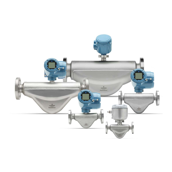
- Page 1 Installation Manual 00825-0100-4630, Rev AA October 2023 Micro Motion ™ G-Series Coriolis Flow and Density Sensors...
- Page 2 Micro Motion employees. If you fail to follow Micro Motion procedures, then Micro Motion will not accept your returned equipment. Return procedures and forms are available on our web support site at Emerson.com, or by calling the Micro Motion Customer Service department.
-
Page 3: Table Of Contents
Installation Manual Contents 00825-0100-4630 October 2023 Contents Chapter 1 Before you begin........................5 1.1 About this document........................5 1.2 Hazard messages........................5 1.3 Related documentation......................6 Chapter 2 Planning............................. 7 2.1 Installation checklist........................7 2.2 Best practices..........................8 2.3 Temperature limits........................8 Chapter 3 Mounting..........................11 3.1 Mount the sensor........................11 Chapter 4 ... - Page 4 Contents Installation Manual October 2023 00825-0100-4630 Micro Motion G-Series...
-
Page 5: Before You Begin
Installation Manual Before you begin 00825-0100-4630 October 2023 1 Before you begin 1.1 About this document This document provides information on planning, mounting, wiring, and grounding the G-Series sensor. The information in this document assumes that users understand basic transmitter and sensor installation, configuration, and maintenance concepts and procedures. -
Page 6: Related Documentation
The hazardous area approvals documentation shipped with the sensor or available www.emerson.com/flowmeasurementhttps://www.emerson.com/en-ca/automation/ micro-motion. • Micro Motion G-Series Flow and Density Meters Product Data Sheet • Micro Motion 9-Wire Flowmeter Cable Preparation and Installation Manual • The transmitter installation guide and the transmitter configuration and use guide... -
Page 7: Chapter 2 Planning
Installation Manual Planning 00825-0100-4630 October 2023 2 Planning 2.1 Installation checklist □ Make sure that the hazardous area specified on the approval tag is suitable for the environment in which the meter will be installed. WARNING Failure to abide by approvals can cause an explosion resulting in injury or death. □... -
Page 8: Best Practices
In all cases, the electronics cannot be operated where the ambient temperature is below -40 °F (-40.0 °C) or above 140 °F (60.0 °C). If a sensor is to be used where the ambient temperature is outside of the range permissible for the electronics, the electronics must Micro Motion G-Series... - Page 9 Installation Manual Planning 00825-0100-4630 October 2023 be remotely located where the ambient temperature is within the permissible range, as indicated by the shaded areas of the temperature limit graphs. Ambient and process temperature limits for all G-Series meters = Ambient temperature °F (°C) = Process temperature °F (°C) proc A = All available electronic options...
- Page 10 Planning Installation Manual October 2023 00825-0100-4630 Micro Motion G-Series...
-
Page 11: Chapter 3 Mounting
The sensor does not require external supports. The flanges will support the sensor in any orientation. • Emerson recommends inserting bolts from the pipeline flange side and placing nuts on the sensor flange side because there is more space on the pipeline flange. Installation Manual... - Page 12 Mounting Installation Manual October 2023 00825-0100-4630 Micro Motion G-Series...
-
Page 13: Chapter 4 Wiring
Installation Manual Wiring 00825-0100-4630 October 2023 4 Wiring 4.1 Options for wiring The wiring procedure you follow depends on which electronics option you have. Table 4-1: Wiring procedures by electronics option Electronics option Wiring procedure Integral transmitter The transmitter is already connected to the sensor. No wiring is required between sensor and transmitter. - Page 14 1. Remove the core processor cover using a flat-blade screw driver. 2. Run the conduit to the sensor. 3. Pull the cable through the conduit. 4. Cut the drain wires and let them float at both ends of the conduit. Micro Motion G-Series...
- Page 15 Installation Manual Wiring 00825-0100-4630 October 2023 4.2.3 Prepare a cable with user-supplied cable glands Procedure 1. Remove the core processor cover using a flat-blade screw driver. 2. Pass the wires through the gland nut and gland body. A. Gland body B. Gland nut 3.
- Page 16 8. Assemble the gland by folding the shield or braid back over the clamping insert and 0.125 in (3 mm) past the O-ring. A. Shield folded back 9. Install the gland body into the conduit opening on the core processor housing. Micro Motion G-Series...
- Page 17 Installation Manual Wiring 00825-0100-4630 October 2023 10. Insert the wires through the gland body and tighten the gland nut onto the gland body. A. Shield folded back B. Gland body 4.2.5 Connect the wires to the core processor terminals After the 4-wire cable has been prepared and shielded (if required), connect the individual wires of the 4-wire cable to the terminals on the core processor.
- Page 18 4. Tighten the screws to hold the wires in place. 5. Ensure integrity of gaskets; then tightly close and seal the junction box cover and all housing covers. 6. Refer to the transmitter installation manual for signal and power wiring instructions. Micro Motion G-Series...
-
Page 19: Chapter 5 Grounding
Installation Manual Grounding 00825-0100-4630 October 2023 5 Grounding The meter must be grounded according to the standards that are applicable at the site. The customer is responsible for knowing and complying with all applicable standards. Prerequisites Use the following guides for grounding practices: •... - Page 20 Grounding Installation Manual October 2023 00825-0100-4630 Micro Motion G-Series...
-
Page 21: Chapter 6 Supplementary Information
Installation Manual Supplementary information 00825-0100-4630 October 2023 6 Supplementary information 6.1 Pressure relief G-Series sensors are available with a rupture disk installed on the case. Rupture disks vent process fluid from the sensor case in the unlikely event of a flow tube breach. The standard rupture activation pressure is 63.8 psig (4.4 barg). - Page 22 Removing the purge fitting, blind plug, or rupture disks compromises the Ex-i Safety Certification, the Ex-tc Safety Certification, and the IP-rating of the Coriolis meter. Any modification to the purge fitting, blind plug, or rupture disks must maintain a minimum of IP66/IP67 Ratings. Micro Motion G-Series...
- Page 23 Installation Manual 00825-0100-4630 October 2023 Installation Manual...
- Page 24 © 2023 Micro Motion, Inc. All rights reserved. The Emerson logo is a trademark and service mark of Emerson Electric Co. Micro Motion, ELITE, ProLink, MVD and MVD Direct Connect marks are marks of one of the Emerson Automation Solutions family of companies. All...