Emerson Micro Motion Quick Start Manual
Liquified natural gas meter
Hide thumbs
Also See for Micro Motion:
- Configuration and use manual (212 pages) ,
- User manual (76 pages) ,
- Installation manual (74 pages)
Table of Contents
Advertisement
Quick Links
Advertisement
Chapters
Table of Contents

Related Manuals for Emerson Micro Motion


Summary of Contents for Emerson Micro Motion
- Page 1 快速安装指南 MMI-20032808, Rev AB 2016 年 12 月 高准(Micro Motion ® )LNG 系列 科里奥利质量流量计和仪表...
- Page 2 其他信息 如需了解完整的产品规格,请参阅产品样本。如需获得故障排查信息,请参阅组态手册。各产品样本和各手册都可访问高准网站 www.micromotion.com/documentation 获取。 返修政策 根据高准规定的程序返修设备。遵循这些程序可确保符合政府运输机构的法规要求, 同时有助于为高准员工提供安全的工作环境。 如未遵循高准返修程序,高准将不会接受返回的设备。 www.micromotion.com 有关于返修程序和返修表格,请登录 获取,或致电高准客户服务部门获取。 Emerson Flow 客户服务 电子邮件: • flow.support@emerson.com 全球: • APflow.support@emerson.com 亚太地区: 电话: 北美和南美 欧洲和中东 亚太地区 800-522-6277 0870 240 1978 800 158 727 美国 英国 澳大利亚 +1 303-527-5200 +31 (0) 704 136 666 新西兰...
-
Page 3: Table Of Contents
目录 目录 第 1 章 安装准备 ..........................1 部件标识 .............................. 1 安装检查表 ............................1 电源要求 .............................. 2 第 2 章 安装方式 ..........................4 安装传感器 ............................4 安装双核处理器(选项 1) ........................4 安装带 MVD Direct Connect 本安型安全栅的增强型核心处理器(选项 2) ........5 第 3 章 接线 ............................8 将核心处理器连接到传感器 ......................... 8 双核处理器接线(选项... - Page 4 目录 高准 LNG 系列科里奥利质量流量计...
-
Page 5: 安装准备
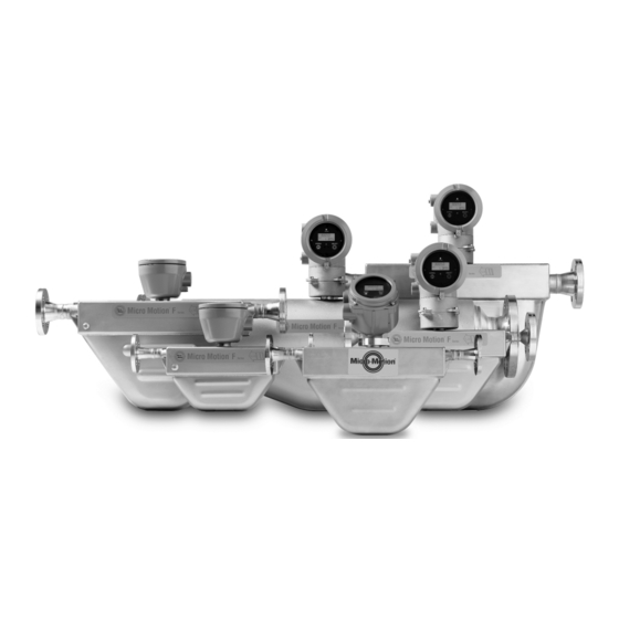
安装准备 本章所涉及的主题: • 部件标识 • 安装检查表 • 电源要求 部件标识 双核处理器 9 线电缆 适用于灌装测量应用的 LNGM10 型仪表 适用于回流测量应用的 LNGS06 型仪表 安装检查表 □ 确保认证标签上规定的危险区域适合于 LNG 仪表的安装环境。 □ 检查当前环境和过程温度,确保其在仪表的限制范围内。 □ 确保核心处理器使用的是低压直流电源。过高的电压可能会损坏核心处理器。 □ 有关本安型应用,请参阅 Micro Motion ATEX、UL 或 CSA 安装说明。 □ 只要导线管的开口不是朝上,您就可以在任何方向安装 LNG 电子元件。 快速安装指南... -
Page 6: 电源要求
安装准备 注意! 若导线管开口朝上,冷凝液可能进入外壳,进而可能损坏内部的电子元件。 □ 安装传感器时, 要保证外壳上的流向箭头与过程介质的实际流向一致。 (流向也可使 用软件进行选择。 ) LNGS06 LNGM10 气体回流传感器 灌装传感器 电源要求 • 18 至 30 V 直流,3 W(典型) ,5 W(最大) • 最小 28 VDC,随附长度为 300 米的 1 mm 电源线 • 启动时,电源在电气部件电源输入端最低电压为 18 V 的条件下必须提供至少 0.5 A 的短暂电流。 •... - Page 7 安装准备 表 1-1: 68 °F (20 °C) 下的典型电源线电阻 (续) 线规 电阻 18 AWG 0.0128 欧/英尺 20 AWG 0.0204 欧/英尺 2.5 平方毫米 0.0136 欧/米 1.5 平方毫米 0.0228 欧/米 1.0 平方毫米 0.0340 欧/米 0.75 平方毫米 0.0460 欧/米 0.50 平方毫米 0.0680 欧/米 快速安装指南...
-
Page 8: 安装方式
安装方式 安装方式 本章所涉及的主题: • 安装传感器 • 安装双核处理器(选项 1) • 安装带 MVD Direct Connect 本安型安全栅的增强型核心处理器(选项 2) 安装传感器 安装 LNGS06。 安装 LNGM10。 安装双核处理器(选项 1) 将双核处理器安装在管道或墙壁上。 高准 LNG 系列科里奥利质量流量计... -
Page 9: 安装带 Mvd Direct Connect 本安型安全栅的增强型核心处理器(选项 2
安装方式 图 2-1: 双核处理器:管道安装型 图 2-2: 双核处理器:墙壁安装型 安装带 MVD Direct Connect 本安型安全栅的增 强型核心处理器(选项 2) 将增强型核心处理器安装在管道或墙壁上。 快速安装指南... - Page 10 安装方式 图 2-3: 增强型核心处理器:管道安装型 图 2-4: 增强型核心处理器:墙壁安装型 将安全栅安装在 DIN 导轨上。 高准 LNG 系列科里奥利质量流量计...
- Page 11 安装方式 图 2-5: DIN 导轨上的安全栅安装 快速安装指南...
-
Page 12: 第 3 章 接线
接线 接线 本章所涉及的主题: • 将核心处理器连接到传感器 • 双核处理器接线(选项 1) • 增强型核心处理器接线(选项 2) 将核心处理器连接到传感器 3.1.1 使用护套电缆连接核心处理器与传感器 先决条件 对于危险区域的安装,请将护套电缆安装在用户自备的密封金属导线管中,该导线管为封 闭的电缆提供 360°端子屏蔽。 注意! • 传感器接线是本安型。为保持传感器接线是本安型,请使传感器接线独立于电源接线和输出 接线。 • 使电缆远离诸如变压器、电机和电源线等设备,这些设备都会产生大磁场。电缆、电缆密封 接头或导管安装不当,可能会导致测量不精确或流量计故障。 • 外壳密封不当可能会使电子部件受潮,进而可能导致测量误差或流量计故障的产生。将滴水 管安装在导管和电缆上(如有必要) 。检查并润滑所有密封垫圈和 O 型圈。完全关闭并拧紧 所有外壳盖和导线管开口。 步骤 将电缆穿过导线管。 在核心处理器处,将各接线的裸端按颜色插入核心处理器末端相应的端子。不得露 出任何裸线。请参见下表。 表 3-1: 核心处理器端子标识 导线颜色 功能... - Page 13 接线 表 3-1: 核心处理器端子标识 (续) 导线颜色 功能 白色 左检测 – 图 3-1: 双核处理器端子 A. 传感器 1 B. 传感器 2 快速安装指南...
- Page 14 接线 图 3-2: 增强型核心处理器端子 A. 棕色 B. 紫色 C. 黄色 D. 橙色 E. 灰色 F. 蓝色 G. 白色 H. 绿色 红色 接地螺钉(黑色) 3.1.2 使用屏蔽电缆连接核心处理器与传感器 先决条件 对于危险区域的安装, 核心处理器末端处的屏蔽电缆安装必须配合使用电缆接头。您可以 从高准购买符合危险区域使用要求的电缆接头。也可以使用其他供应商的电缆接头。 注意! • 传感器接线是本安型。为保持传感器接线是本安型,请使传感器接线独立于电源接线和输出 接线。 • 使电缆远离诸如变压器、电机和电源线等设备,这些设备都会产生大磁场。电缆、电缆密封 接头或导管安装不当,可能会导致测量不精确或流量计故障。 • 外壳密封不当可能会使电子部件受潮,进而可能导致测量误差或流量计故障的产生。将滴水 管安装在导管和电缆上(如有必要) 。检查并润滑所有密封垫圈和 O 型圈。完全关闭并拧紧 所有外壳盖和导线管开口。...
- Page 15 接线 图 3-3: 电缆接头和电缆(分解图) A. 电缆 B. 密封螺母 C. 压紧螺母 D. 黄铜压缩环 E. 编织屏蔽层 F. 电缆 G. 胶带或热缩管 H. 卡座(图示为螺纹接头的组成部分) 螺纹接头 拧松压紧螺母中的螺纹接头。 将螺纹接头拧到 9 线制电缆的导线管开口上。用手拧紧它后再转一圈。 将压缩环、压紧螺母和密封螺母滑到电缆上。确保压缩环正确定向,以便锥形部分 与螺纹接头的锥形端正确接合。 将电缆末端穿过螺纹接头,使编织屏蔽层滑到螺纹接头的锥形端上。 将压缩环滑到编织屏蔽层上。 将压紧螺母拧到螺纹接头上。用手拧紧密封螺母和压紧螺母,确保压缩环可以固定 编织屏蔽层。 使用 25 毫米(1 英寸)扳手拧紧密封螺母和压紧螺母,扭矩为 20–25 英尺磅 (27–34 牛顿-米) 。参见图 3-4, 了解一个完整的电缆接头装配图示。 快速安装指南...
- Page 16 接线 图 3-4: 组装的电缆接头和电缆的横截面 A. 电缆 B. 密封螺母 C. 密封件 D. 压紧螺母 E. 编织屏蔽层 F. 黄铜压缩环 G. 螺纹接头 拆下核心处理器盖。 在核心处理器处,根据以下程序连接电缆: a. 将各接线的裸端按颜色插入核心处理器末端相应的端子。不得露出任何裸线。 请参见下表。 表 3-2: 核心处理器端子标识 导线颜色 功能 黑色 屏蔽线 驱动 + 棕色 红色 驱动 – 橙色 温度 – 黄色 温度回升...
- Page 17 接线 图 3-5: 双核处理器端子 A. 传感器 1 B. 传感器 2 图 3-6: 增强型核心处理器端子 A. 棕色 B. 紫色 C. 黄色 D. 橙色 E. 灰色 F. 蓝色 G. 白色 H. 绿色 红色 接地螺钉(黑色) b. 拧紧螺钉,以将接线固定到位。 c. 请确保垫圈完好,并为所有 O 型圈涂抹润滑脂,然后装回核心处理器外壳盖并 根据需要拧紧所有螺钉。 快速安装指南...
-
Page 18: 双核处理器接线(选项 1
步骤 拆下双核处理器外壳盖。 将各条线的裸端插入接线端子中。确保没有任何线缆暴露在外。 按照匹配的颜色接线(参见表 3-1) 。 A. 传感器 1 B. 传感器 2 如果线长不是 3 米,则使用 ProLink III 来寄存不同的长度。有关更多信息,请参阅 ® ® (Micro Motion ) LNG 系列科里奥利质量流量计和密度仪表组态和使用手册。 高准 3.2.2 双核处理器电源接线 先决条件 根据高准 LNG 系列科里奥利质量流量计安装指南中的说明来准备和安装电缆。 步骤 将电源线连接至正极 (+) 端子和负极 (-) 端子。 将正极线连接到红色正极 (+) 端子,将负极线连接到黑色负极 (-) 端子。... - Page 19 接线 A. 电源 3.2.3 双核处理器输出接线 先决条件 根据高准 LNG 系列科里奥利质量流量计安装指南中的说明来准备和安装电缆。 步骤 将 RS-485 线连接至白色 RS485A 和绿色 RS485B 接口。 A. RS-485 B. 服务端口 快速安装指南...
-
Page 20: 增强型核心处理器接线(选项 2
接线 增强型核心处理器接线(选项 2) 根据本节说明来安装增强型核心处理器。 3.3.1 在增强型核心处理器上连接 9 线电缆 先决条件 根据高准 LNG 系列科里奥利质量流量计安装指南中的说明来准备和安装电缆。 步骤 将各条线的裸端插入接线端子中。确保没有任何线缆暴露在外。 按照匹配的颜色接线(参加表 3-1) 。 拧紧螺钉,以将接线固定到位。 确保垫圈完好,然后紧紧关闭并密封所有外壳盖。 3.3.2 MVD Direct Connect 本安型安全栅接线 先决条件 根据高准 LNG 系列科里奥利质量流量计安装指南中的说明来准备和安装电缆。 步骤 将增强型核心处理器连接到安全栅: a. 将 RS-485 线从增强型核心处理器连接到安全栅上的本安型 RS-485 端子(端子 43 和 44) ,匹配 A 和 B。请参见下表和下图。 b. - Page 21 接线 图 3-7: 安全栅端子 A. 用于连接至增强型核心处理器的本安型端子 B. 用于连接至远程主机和电源的非本安型端子 3.3.3 将电源连接到 MVD Direct Connect 本安型安全栅 • 只要每个装置都能获得足够的电能, 您可以将多个 MVD Direct Connect 装置连接到 单个电源。 • 本安型安全栅的电源同时也可以用于对其他设备供电。 步骤 从安全栅连接电源线,匹配正极和负极(+ 和 –) 。 图 3-8: 安全栅端子 A. 用于连接至增强型核心处理器的本安型端子 B. 用于连接至远程主机和电源的非本安型端子 3.3.4 将远程主机连接到 MVD Direct Connect 本安型安全栅 将...
- Page 22 接线 图 3-9: 安全栅端子 A. 用于连接至增强型核心处理器的本安型端子 B. 用于连接至远程主机和电源的非本安型端子 远程主机上屏蔽线端接。 切勿增加外部电阻。安全栅包含内部上拉/下拉电阻和端接电阻。 高准 LNG 系列科里奥利质量流量计...
-
Page 23: 第 4 章 接地
接地 接地 本章所涉及的主题: • 双核处理器接地 • 增强型核心处理器接地 仪表必须按照现场适用的标准进行接地。客户有责任了解并遵守所有适用标准。 高准建议根据以下指导进行接地操作: • 使用铜线,2.0 mm 或更大线径。 • 所有接地导线应尽可能短,阻抗小于 1 欧姆。 • 将接地导线直接接地,或者按照工厂标准操作。 双核处理器接地 如需安装双核处理器,请遵循本程序。 注 将处理器接地,或者遵照设备的接地网络要求。接地不当可能导致测量误差。 步骤 如果管道中的接头未接地,则将接地线连接到双核处理器上的内部或外部接地螺钉。 图 4-1: 双核处理器接地螺钉 A. 内部接地螺钉 B. 外部接地螺钉 快速安装指南... -
Page 24: 增强型核心处理器接地
接地 增强型核心处理器接地 如需安装增强型核心处理器,请遵循本程序。 注 将处理器接地,或者遵照设备的接地网络要求。接地不当可能导致测量误差。 步骤 如果管道中的接头未接地,则将接地线连接到增强型核心处理器上的内部或外部接地螺 钉。 图 4-2: 增强型核心处理器接地螺钉 A. 内部接地螺钉 B. 外部接地螺钉 C. 内部接地螺钉 高准 LNG 系列科里奥利质量流量计... -
Page 25: 基础组态
基础组态 基础组态 本章所涉及的主题: • 通电 • 传感器启动检查表 • 规格 通电 给流量计通电之前,请关闭并拧紧所有外壳盖。 警告! 在盖子尚未安装到位的情况下运行传感器会产生触电危险, 进而导致死亡、 伤害或财产损失。 确保用于现场接线的安全栅隔离和保护盖、以及电路板所在腔体、电子元件模块及外壳在处 理器通电之前全都安装到位。 警告! 若在危险区域使用服务端口进行通讯,则可能引起爆炸。在危险区域使用服务端口与核心处 理器通讯之前,确保周围气体中不含有爆炸性气体。 打开供电电源。传感器将自动执行诊断例程。传感器通电程序结束后,核心处理器 将在贸易交接安全模式下工作,不会产生报警。 注 随后,传感器即可在通电大约一分钟(这个时间因具体型号而异)之后开始接收过程介质。 但电子元件要预热到平衡状态,则需要大约十分钟。在这十分钟内,处理器可能稍微有点不 稳定或不准确。 传感器启动检查表 安装检查表 □ 将法兰和垫圈牢固地安装在仪表两侧 □ 对仪表上下游的管道进行支撑 □ 流向箭头与过程流向一致 □ 上下游阀门正确打开或关闭 □ 电缆连接点已密封且连接牢固 电源接线检查表 □ 正极端子... - Page 26 基础组态 □ 18 至 30 VDC 规格 物理特性 304L 不锈钢 传感器外壳 电子元件外壳 聚氨酯涂层铝质 316L 不锈钢 接液材料 LNGS06 重量 4.6 kg LNGM10 重量 7.9 kg 含 EN1092-1 PN40 F316/316L 对焊法兰 入口:两个 3/4″ NPT 导管母口用于供 9 线制接 电缆密封接头入口 线连接至 LNG 传感器 出口:两个 1/2”— 14 NPT 或 M20 X 1.5 导管母 口用于输出和电源...
- Page 27 基础组态 LNGS06 LNGM10 精度和流量 ±1.0℃ 加/减(±) 读数的 0.5% ±1.0℃ 加/减(±) 读数的 0.5% 温度精度 (过程温度范围:–100℃至 (过程温度范围:–100℃至 60℃) 60℃) ±1.0℃ 加/减(±) 读数的 1.0% ±1.0℃ 加/减(±) 读数的 1.0% (过程温度范围:-196℃ (过程温度范围:-196℃ 至-100℃) 至-100℃) 1800 kg/hr 18000 kg/hr 液体的最大流量 注 如要确定仪表性能,典型的批量测量/配送流量如下: • 批处理时间不少于 3 分钟。 •...
- Page 28 邮编:710065 电话:86-29-8865 0888 传真:86-29-8865 0899 © 2016 Micro Motion, Inc. 保留所有权利 深圳办事处 深圳市南山区海德三道 Micro Motion 和 Emerson 标志是艾默生电气公司的注册商标和服 天利中央商务广场 B 座 1803 务商标。Micro Motion、 ELITE、 MVD、 ProLink、 MVD Direct Connect 邮编: 518054 以及 PlantWeb 均为艾默生过程管理子公司的标志。所有其他商标 电话:86-755-8659 5099 均为它们各自所有者的资产。 传真:86-755-8659 5095...
- Page 29 Quick Start Guide MMI-20032808, Rev AB December 2016 ® Micro Motion Liquified Natural Gas Meter...
- Page 30 Micro Motion employees. Micro Motion will not accept your returned equipment if you fail to follow Micro Motion procedures. Return procedures and forms are available on our web support site at www.micromotion.com, or by phoning the Micro Motion Customer Service department.
- Page 31 Contents Contents Chapter 1 Planning ...........................1 Component identification ......................1 Installation checklist ........................1 Power requirements ........................2 Chapter 2 Mounting .........................4 Mount the sensors ..........................4 Mount the dual core processor (option 1) ..................4 Mount the enhanced core processor with MVD Direct Connect I.S. Barrier (option 2) .....5 Chapter 3 Wiring ..........................
- Page 32 Contents Micro Motion Liquified Natural Gas Meter...
-
Page 33: Chapter 1 Planning
Planning Planning Topics covered in this chapter: • Component identification • Installation checklist • Power requirements Component identification Dual core processor 9-wire cable Model LNGM10 for filling measurement Model LNGS06 for returning measurement Installation checklist □ Make sure that the hazardous area specified on the approval tag is suitable for the environment in which the LNG meters will be installed. -
Page 34: Power Requirements
Verify that you are using low-voltage DC power for the core processor. Excess voltage can damage the core processor. □ For I.S. applications, refer to Micro Motion ATEX, UL, or CSA installation instructions. □ Mount the LNG electronics in any orientation as long as the conduit openings do not point upward. - Page 35 Planning Cable sizing formula M = 18V + (R x L x 0.2A) • M: minimum supply voltage • R: cable resistance • L: cable length Table 1-1: Typical power cable resistance at 68 °F (20 °C) Wire gauge Resistance 0.0050 Ω/ft 14 AWG 0.0080 Ω/ft...
-
Page 36: Chapter 2 Mounting
Mount the enhanced core processor with MVD Direct Connect I.S. Barrier (option 2) Mount the sensors Mount the LNGS06. Mount the LNGM10. Mount the dual core processor (option 1) Mount the dual core processor on either a pipe or a wall. Micro Motion Liquified Natural Gas Meter... -
Page 37: Mount The Enhanced Core Processor With Mvd Direct Connect I.s. Barrier (Option 2)
Mounting Figure 2-1: Dual core processor: pipe mount Figure 2-2: Dual core processor: wall mount Mount the enhanced core processor with MVD Direct Connect I.S. Barrier (option 2) Mount the enhanced core processor on either a pipe or a wall. Quick Start Guide... - Page 38 Mounting Figure 2-3: Enhanced core processor: pipe mount Figure 2-4: Enhanced core processor: wall mount Mount the barrier on a DIN rail. Micro Motion Liquified Natural Gas Meter...
- Page 39 Mounting Figure 2-5: Barrier mount on DIN rail Quick Start Guide...
-
Page 40: Chapter 3 Wiring
No bare wires should remain exposed. See the following table. Table 3-1: Core processor terminal designations Wire color Function Black Drain wires Brown Drive + Drive – Micro Motion Liquified Natural Gas Meter... - Page 41 Wiring Table 3-1: Core processor terminal designations (continued) Wire color Function Orange Temperature – Yellow Temperature return Green Left pickoff + Blue Right pickoff + Violet Temperature + Gray Right pickoff – White Left pickoff – Figure 3-1: Dual core processor terminals A.
- Page 42 For hazardous area installations, shielded cable must be installed with cable glands at the core processor end. Cable glands that meet hazardous area requirements can be purchased from Micro Motion. Cable glands from other vendors can be used. CAUTION! •...
- Page 43 Wiring Figure 3-3: Cable gland and cable (exploded view) A. Cable B. Sealing nut C. Compression nut D. Brass compression ring E. Braided shield F. Cable G. Tape or heat-shrink tubing H. Clamp seat (shown as integral to nipple) Nipple Unscrew the nipple from the compression nut.
- Page 44 Function Black Drain wires Brown Drive + Drive – Orange Temperature – Yellow Temperature return Green Left pickoff + Blue Right pickoff + Violet Temperature + Gray Right pickoff – White Left pickoff – Micro Motion Liquified Natural Gas Meter...
- Page 45 Wiring Figure 3-5: Dual core processor terminals A. Sensor 1 B. Sensor 2 Figure 3-6: Enhanced core processor terminals A. Brown B. Violet C. Yellow D. Orange E. Gray F. Blue G. White H. Green Ground screw (black) Quick Start Guide...
-
Page 46: Wire The Dual Core Processor (Option 1)
Use this section for a dual core processor installation. 3.2.1 Connect the 9-wire cable on a dual core processor Prerequisites Prepare and install the cable according to the instructions in the Micro Motion Liquified Natural Gas Meter Installation Guide. Procedure Remove the dual processor housing cover. - Page 47 3.2.2 Wire the dual core processor power supply Prerequisites Prepare and install the cable according to the instructions in the Micro Motion Liquified Natural Gas Meter Installation Guide. Procedure Connect the power supply wires to the positive (+) and negative (–) terminals.
-
Page 48: Wire The Enhanced Core Processor (Option 2)
3.3.1 Connect the 9-wire cable on an enhanced core processor Prerequisites Prepare and install the cable according to the instructions in the Micro Motion Liquified Natural Gas Meter Installation Guide. Procedure Insert the stripped ends of the individual wires into the terminal blocks. Ensure that no bare wires remain exposed. - Page 49 Wiring Procedure Connect the enhanced core processor to the barrier: a. Connect the RS-485 wires from the enhanced core processor to the I.S. RS-485 terminals at the barrier (terminals 43 and 44), matching A and B. See the following table and figure. b.
- Page 50 B. Non I.S. terminals for connection to remote host and power supply 3.3.4 Wire the remote host to the MVD Direct Connect I.S. Barrier Connect the RS-485 wire from the barrier to the RS-485 terminals at the remote host. Micro Motion Liquified Natural Gas Meter...
- Page 51 Wiring Figure 3-9: Barrier terminals A. I.S. terminals for connection to enhanced core processor B. Non I.S. terminals for connection to remote host and power supply Terminate the shields at the remote host. Do not add external resistors. The barrier contains internal pull-up/pull-down and termination resistors.
-
Page 52: Chapter 4 Grounding
The meter must be grounded according to the standards that are applicable at the site. The customer is responsible for knowing and complying with all applicable standards. Micro Motion suggests the following guides for grounding practices: • Use copper wire, 2,0 mm or larger wire size. -
Page 53: Ground The Enhanced Core Processor
Grounding Figure 4-1: Dual core processor grounding screws A. Internal grounding screws B. External grounding screw Ground the enhanced core processor Use this procedure if your installation contains an enhanced core processor. Note Ground the processor to earth, or follow ground network requirements for the facility. Improper grounding can cause measurement error. - Page 54 Grounding Figure 4-2: Enhanced core processor grounding screws A. Internal ground screw B. External ground screw C. Internal ground screw Micro Motion Liquified Natural Gas Meter...
-
Page 55: Chapter 5 Basic Configuration
Basic configuration Basic configuration Topics covered in this chapter: • Power on • Sensor start up checklist • Specifications Power on Before you apply power to the sensors, close and tighten all housing covers. WARNING! Operating the sensor without covers in place creates electrical hazards that can cause death, injury, or property damage. -
Page 56: Specifications
MVD Direct Connect I.S. barrier Digital communications Modbus / RS-485 accepts data rates 4800, 9600, 19200, and 38400 baud for dual core pro- cessor and enhanced core processor with MVD Direct Connect I.S. barrier Micro Motion Liquified Natural Gas Meter... - Page 57 Basic configuration Output signals Measurement variables • Mass flow • Temperature Accuracy and flow rate Accuracy and flow rate LNGS06 LNGM10 Batch accuracy ±1.0% of batch ±0.5% of batch Temperature accuracy ±1.0 °C ±0.5% of reading (proc- ±1.0 °C ±0.5% of reading (proc- ess temperature: -100 to 60 °C) ess temperature: -100 to 60 °C) ±1.0 °C ±1.0% of reading (proc-...
- Page 58 © Micro Motion Japan 2016 Micro Motion, Inc. All rights reserved. Emerson Automation Solutions The Emerson logo is a trademark and service mark of Emerson 1-2-5, Higashi Shinagawa Electric Co. Micro Motion, ELITE, ProLink, MVD and MVD Direct Shinagawa-ku Connect marks are marks of one of the Emerson Automation Tokyo 140-0002 Japan Solutions family of companies.