Table of Contents
Advertisement
Quick Links
ICFDV Series Direct Vent Gas Fireplace Insert
Installation and Operating Instructions
Models: ICFDV40LNTSCSB, ICFDV40CNTSCSB
WARNING:
FIRE OR EXPLOSION HAZARD
Failure to follow safety warnings exactly
could result in serious injury, death or
property damage.
•
Do not store or use gasoline or other
flammable vapors and liquids in the
vicinity of this or any other appliance.
•
WHAT TO DO IF YOU SMELL GAS
– Do not try to light any appliance.
– Do not touch any electrical switch; do
not use any phone in your building.
– Leave the building immediately.
– Immediately call your gas supplier from
a neighbor's phone. Follow the gas
supplier's instructions.
– If you cannot reach your gas supplier,
call the fire department.
•
Installation and service must be performed
by a qualified installer, service agency or
the gas supplier.
WARNING: Improper installation, adjustment,
alteration, service or maintenance can cause
injury or property damage. Refer to this manual.
For assistance or additional information consult
a qualified installer, service agency or the
gas supplier.
This appliance may be installed in an aftermarket,*
permanently located, manufactured home (USA
only) or mobile home, where not prohibited by
local codes.
This appliance is for use only with the type of gas
indicated on the rating plate. This appliance is
not convertible for use with other gases, unless
a certified kit is used.
* Aftermarket: Completion of sale, not for purpose of resale, from
the manufacturer.
DANGER
4852
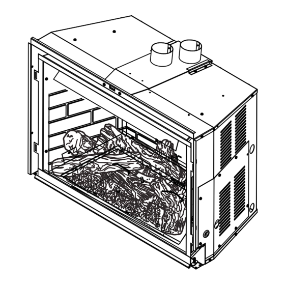
ICFDV40 insert cover
A barrier designed to reduce the risk of burns from the hot
viewing glass is provided with this appliance and shall
be installed for the protection of children and
other at risk individuals.
INSTALLER: Leave this manual with the appliance.
CONSUMER: Retain this manual for
future reference.
CERTIFIED
S
B
AFETY
ARRIER
HOT GLASS WILL
CAUSE BURNS.
DO NOT TOUCH GLASS
UNTIL COOLED.
NEVER ALLOW CHILDREN
TO TOUCH GLASS.
20306751 3/15 Rev. 2
20306543
Advertisement
Table of Contents
Troubleshooting

Related Manuals for Vermont Castings ICFDV40LNTSCSB


Summary of Contents for Vermont Castings ICFDV40LNTSCSB
- Page 1 ICFDV Series Direct Vent Gas Fireplace Insert Installation and Operating Instructions Models: ICFDV40LNTSCSB, ICFDV40CNTSCSB CERTIFIED WARNING: AFETY ARRIER FIRE OR EXPLOSION HAZARD Failure to follow safety warnings exactly could result in serious injury, death or property damage. • Do not store or use gasoline or other flammable vapors and liquids in the vicinity of this or any other appliance.
-
Page 2: Table Of Contents
ICFDV40 Fireplace Insert CONTENTS Thank you and congratulations on your purchase of a Vermont Castings Group Fireplace Insert. PLEASE READ THE INSTALLATION AND OPERATION INSTRUCTIONS BEFORE USING THE APPLIANCE! IMPORTANT: Read all instructions and warnings carefully before starting installation. Failure to follow these instructions may result in a possible fire hazard and will void the warranty. -
Page 3: Important Safety Information
ICFDV40 Fireplace Insert IMPORTANT SAFETY INFORMATION OWNER INSTALLER Please leave these instructions with the appliance. Please retain these instructions for future reference. WARNING: • Read this owner’s manual carefully and completely before trying to assemble, operate, or service this fireplace. •... -
Page 4: Code Approval
ICFDV40 Fireplace Insert IMPORTANT SAFETY INFORMATION & CODE APPROVAL 12. You must keep control compartments, burners, and IMPORTANT: circulating air passages clean. More frequent cleaning PLEASE READ THE FOLLOWING may be needed due to excessive lint and dust. Turn off CAREFULLY the gas valve and pilot light before cleaning fireplace. -
Page 5: Product Features
ICFDV40 Fireplace Insert PRODUCT FEATURES PRODUCT SPECIFICATIONS • This appliance has been certified for use with either natural or propane gas. Refer to the appropriate data plates. • This appliance is not for use with solid fuels. • The appliance is approved for bedroom or bedsitting room installations. -
Page 6: Insert Dimensions
ICFDV40 Fireplace Insert INSERT DIMENSIONS 24 ⁄ ” (621 mm) 13¼” (337 mm) 2 ⁄ ” 12½” (56 mm) (318 mm) 5 ⁄ ” (144 mm) 18 ⁄ " 23 ⁄ " (460 mm) (586 mm) 26 ⁄ ” (668 mm) 29 ⁄... -
Page 7: General Installation Information
ICFDV40 Fireplace Insert GENERAL INSTALLATION INFORMATION BEFORE YOU START Your remote control receiver must "learn" the signal code from your hand-held trans- Read this homeowner manual thoroughly and follow all mitter. This operation should be performed instructions carefully. Inspect all contents for shipping with power applied to the fireplace but before damage and immediately inform your dealer if any damage the fireplace is installed into the fireplace... -
Page 8: Clearances
ICFDV40 Fireplace Insert CLEARANCES INSERT CLEARANCES No combustibles (ie: drapes, doors) may be within, or swing within 36" of the front of the insert. Finish Wall 12" (305 mm) 12” (305 mm) Maximum Depth 14" Side Wall (355 mm) Noncombustible Material Required up to 9"... -
Page 9: Installation
INSTALLATION ICFDV40 Fireplace Insert INSERT PLACEMENT • The insert must be placed within a code-conforming masonry fireplace or a tested and listed zero-clearance (UL-127, solid fuel) fireplace. Repair any fireplace damage prior to installation. • Because the insert uses a circulation blower, clean the fireplace, smoke shelf and chimney before installing. -
Page 10: Zero-Clearance Fireplace Requirements
ICFDV40 Fireplace Insert INSTALLATION ZERO-CLEARANCE (METAL) FIREPLACE Insulation REQUIREMENTS • The damper and grate must be removed. • The smoke shelf, internal baffles, screen, refractory and Shelf metal or glass doors may be removed (if applicable). • Do not remove or alter the insulation or any structured Masonry Lining or Refractory rigid frame members (metal sides, floor, door frames, face of the fireplace, etc.). -
Page 11: Venting Installation
Installation of any damaged venting component. • Unauthorized modification of the venting system. • Installation of any component part not manufactured or approved by Vermont Castings Group. • Installation other than permitted by these instruc- Maximum Height 40' tions. (12.9 m) Minimum Height 10' This insert must be vented to the outside. -
Page 12: Altitude Considerations
ICFDV40 Fireplace Insert VENTING INSTALLATION ALTITUDE CONSIDERATIONS Failure to adjust air shutter properly may This heater has been tested at altitudes ranging from sea lead to improper combustion which can level to 4,500 feet (1,370 m). In this testing, heater with create a safety hazard. -
Page 13: Intake/Exhaust Manifold Removal And Vent Installation
ICFDV40 Fireplace Insert VENTING INSTALLATION INTAKE/EXHAUST MANIFOLD REMOVAL AND VENT INSTALLATION Plate Assembly The intake/exhaust manifold is shipped attached to insert. It may be removed to allow tight installation. 1. Unfasten the two (2) machine screws on the face of the unit and release the plate assembly by sliding the plate back. -
Page 14: Glass Frame Removal
ICFDV40 Fireplace Insert GLASS FRAME REMOVAL GLASS FRAME REMOVAL DANGER NOTE: You must first remove the safety barrier before you remove the glass frame. To remove the barrier, simply lift up and pull out until the tabs are clear of their corresponding slots on the firebox. -
Page 15: Insert Installation
INSERT INSTALLATION ICFDV40 Fireplace Insert CHECK GAS TYPE Use proper gas type for the insert you are installing. If you 100 gal. (min. have conflicting gas type, do not install insert. See dealer External Propane/LP Regula- where you purchased the insert for proper insert according Supply Tank to your gas type. - Page 16 ICFDV40 Fireplace Insert INSERT INSTALLATION A manual shut-off valve is factory installed Only persons licensed to work with gas upstream of the appliance. Union tee and piping may make the necessary gas con- plugged 1/8" NPT pressure tapping point nections to this appliance. should be installed upstream of the appli- ance.
-
Page 17: Check Gas Pressure
ICFDV40 Fireplace Insert CHECK GAS PRESSURE Pressure Inlet 1. Check gas type. The gas supply must be the same as stated on the appliance’s rating decal. If the gas supply is different from the fireplace, STOP! Do not install the appliance. -
Page 18: Electrical Installation
ICFDV40 Fireplace Insert ELECTRICAL INSTALLATION ELECTRICAL WIRING Label all wires before disconnecting This insert will work without any electrical supply. Electricity when servicing controls. Wiring errors is only needed to operate blower. can cause improper and dangerous Verify proper operation after servicing. operation. -
Page 19: Firebrick Installation
ICFDV40 Fireplace Insert FIREBRICK INSTALLATION FIREBRICK INSTALLATION 5. Carefully place right or left side brick panel in place IMPORTANT: Fireplace must have an approved brick kit making sure front edge of brick is behind the front brick and/or porcelain panel kit installed before operation. retainer bracket. -
Page 20: Rock Wool And Log Placement
ICFDV40 Fireplace Insert ROCK WOOL AND LOG PLACEMENT Before you begin - This unit is supplied with six (6) ceramic fiber logs. Do not handle these logs with your bare hands. Do not use the entire bag of rock wool Always wear gloves to prevent skin irritation from to cover burner area. -
Page 21: Glass And Stone Installation
GLASS & STONE INSTALLATION ICFDV40 Fireplace Insert 5. Position Log #3 over Log #1 by aligning the indentation 8. Position Log #6 over Log #5 by aligning the bottom of on Log #3 over the protrusion of Log #1. Figure 24 the log over the cut out on Log #5. -
Page 22: Glass And Stone Placement
ICFDV40 Fireplace Insert SURROUND INSTALLATION INSTALL COMMAND CENTER NOTE: Must be done prior to installing surround. 1. Remove Command Center from box in finsh bag. 2. Attach wires from control board to the Command Center. Figure 29 3. Insert Command Center into tabs on the lower right corner of the surround. -
Page 23: Safety Barrier Installation
SAFETY BARRIER INSTALLATION ICFDV40 Fireplace Insert SAFETY BARRIER INSTALLATION DANGER INSTRUCTIONS CERTIFIED HOT GLASS WILL CAUSE BURNS. AFETY ARRIER DO NOT TOUCH GLASS UNTIL COOLED. NEVER ALLOW CHILDREN TO TOUCH GLASS. NOTE: A barrier designed to reduce the risk of burns A barrier designed to reduce the risk of burns from from the hot viewing glass is provided with this the hot viewing glass is provided with this... -
Page 24: Operating Instructions
ICFDV40 Fireplace Insert OPERATING INSTRUCTIONS FOR YOUR SAFETY READ BEFORE LIGHTING If you do not follow these instructions exactly, a fire or explosion may result causing property damage, personal injury or loss of lie. A. This appliance is equipped with an ignition device which automatically lights the pilot. Refer to the instructions. -
Page 25: Operating Instructions
ICFDV40 Fireplace Insert OPERATING INSTRUCTIONS OPERATING INSTRUCTIONS 1. STOP! Read the safety information above. 2. This appliance is equipped with an ignition device which automatically lights the burner. Do not try to light the burner by hand. 3. With five (5) minutes to clear out any gas. Then smell for gas, including near the floor. If you smell gas, STOP! Follow "B"... -
Page 26: Signature Command System Operation
ICFDV40 Fireplace Insert SIGNATURE COMMAND SYSTEM OPERATION INSTRUCTIONS FEATURES To Install Batteries (not included): 1. Press down the battery door tabs and pull out to remove Command Center battery door. • 2. Install the batteries as indicated on Command Center. Easy Access Function Operation and System Config- uration 3. -
Page 27: Remote Transmitter Learn Function
SIGNATURE COMMAND SYSTEM OPERATION INSTRUCTIONS ICFDV40 Fireplace Insert • REMOTE TRANSMITTER LEARN FUNCTION The Intermittent Pilot Mode is ideal for maximum effi- ciency, igniting the pilot only when needed to start your (DEFAULT OFF) fireplace, lowering fuel consumption and reducing your NOTE: To access the Control Board, remove the access carbon footprint. -
Page 28: Functions/Operation
ICFDV40 Fireplace Insert SIGNATURE COMMAND SYSTEM OPERATION INSTRUCTIONS FUNCTIONS/OPERATION (with Command two presses will decrease the flame height to medium Center) and low. 3. The third press on OFF will turn off the main burner. In Turning on the fireplace standing pilot configuration, the pilot will stay;... -
Page 29: Touch Screen Remote Control Operation
ICFDV40 Fireplace Insert TOUCH SCREEN REMOTE CONTROL OPERATION Due to the sensitive temperature monitoring components in the transmitter, it is necessary to allow the transmitter to stabilize to room temperature before accurate room tempera- tures are displayed. If the transmitter is acti- vated from a severe cold condition, allow 15 minutes for accurate temperature readings to appear on the LCD display. - Page 30 ICFDV40 Fireplace Insert TOUCH SCREEN REMOTE CONTROL OPERATION Master Switch Setting Privacy Code on Transmitter: Figure 38 The remote transmitter privacy code is preset in factory. In the event of activation or interference from other near- by transmissions, change the code using the following procedures (learn function must be performed after changing the code): 1.
- Page 31 ICFDV40 Fireplace Insert TOUCH SCREEN REMOTE CONTROL OPERATION 1. Press the ON/up button to turn b. Use the OFF/down buttons on the fireplace. The flame icon to decrease the Set Time to on the LCD displays High. zero Or c. Slide down on the arrow 2.
- Page 32 ICFDV40 Fireplace Insert TOUCH SCREEN REMOTE CONTROL OPERATION thermostat and the regular Thermostat Mode. The icon 4. After the signal is sent, the ON/up and OFF/down but- “Smart Mode” will appear under the Set Temperature. tons become flame height controller again. The transmitter will automatically adjust the flame height 5.
-
Page 33: Safety Features
ICFDV40 Fireplace Insert TOUCH SCREEN REMOTE CONTROL OPERATION 4. After the signal is sent, the On/up and Off/down but- 2. When the current setting is B), pressing TIMER button tons become flame height controller again. and THERMO button at the same time for 3 seconds will switch to A) Mode. -
Page 34: Using The Mounting Base
ICFDV40 Fireplace Insert TOUCH SCREEN REMOTE CONTROL OPERATION n Using the Mounting Base The transmitter comes with a mounting base which allows you to hang the transmitter on the wall. 1. Secure the mounting base on the wall with supplied screws. -
Page 35: Signature Command Troubleshooting
ICFDV40 Fireplace Insert TROUBLESHOOTING SIGNATURE COMMAND SYSTEM OPERATION FAULT ACTION DIAGNOSIS Using Battery polarity wrong? Re-install batteries battery? Make sure Command Install batteries and/or Battery voltage low? Change batteries Center and plug in the AC board No beep in about the control 8 seconds board are... -
Page 36: Air Shutter Adjustment
ICFDV40 Fireplace Insert AIR SHUTTER ADJUSTMENT (NATURAL GAS ONLY) ADJUSTING THE AIR SHUTTER • To increase air mixture, loosen the screw to open the shutter more. This will reduce soot formation. Figure The venturi under the burner is equipped with an air shut- ter. -
Page 37: Cleaning And Maintenance
ICFDV40 Fireplace Insert CLEANING AND MAINTENANCE Make sure the gas valve knob is in the “OFF” position. Sensor Wait at least five (5) minutes before start -ing maintenance. VENTING SYSTEM Thermopile A qualified agency should examine the venting system annually. CLEANING GLASS Clean the ceramic glass periodically. -
Page 38: Yearly Service Procedure
ICFDV40 Fireplace Insert CLEANING AND MAINTENANCE YEARLY SERVICE PROCEDURE 4. Remove rock wool or decorative glass. Clean burner and burner ports. Figure 54 Failure to inspect and maintain heater may lead to im- 5. Replace log set and rock wool or stones and glass proper combustion and a potentially dangerous situation. -
Page 39: Replacement Parts
ICFDV40 Fireplace Insert REPLACEMENT PARTS WARNING: Failure to position the parts in accordance with these diagrams or failure to use only parts specifically approved with this appliance may result in property damage or personal injury. 4852 20306751 ICFDV40 parts... -
Page 40: Replacement Parts And Required Accessories
ICFDV40 Fireplace Insert REPLACEMENT PARTS AND REQUIRED ACCESSORIES Ref. Description Qty. ICFDV40LNTSC ICFDV40CNTSC 1. Log #1 20305212K 2. Log #2 20305213K 3. Log #3 20305214K 4. Log #4 20305215K 5. Log #5 20305216K 6. Log #6 20305217K 7. Stone xx White 20303043K 8. -
Page 41: Optional Accessories
OPTIONAL ACCESSORIES ICFDV40 Fireplace Insert OPTIONAL ACCESSORIES - ICFDV40 FP2953 Ref. Description Dimensions Part No. sm surr 3 side ctrl FP2951 Small, 3-sided Surround with side control 29"H x 40 ⁄ "W x 4"D ICF40S3B4 med surr 3 side ctrl access, black Medium, 3-sided Surround with side control 36"H x 48"W x 4"D... -
Page 42: For Massachusetts Residents Only
ICFDV40 Fireplace Insert MASSACHUSETTS RESIDENTS ONLY — PLEASE READ AND FOLLOW THESE SPECIAL REQUIREMENTS NOTE REGARDING VENTED PRODUCTS 2. Approved Carbon Monoxide Detectors. Each carbon This product must be installed by a licensed plumber or gas fitter monoxide detector as required in accordance with the above when installed within the Commonwealth of Massachusetts. -
Page 43: Warranty
(3) years. Labor rates will be determined by Vermont Castings Group’s published labor rates in effect at the time labor is performed. -
Page 44: Efficiencies
ICFDV40 Fireplace Insert Based on CSA P.4.1-09 EFFICIENCY RATINGS EnerGuide Ratings D.O.E. Model Fireplace Efficiency (%) (AFUE %) ICFDV40LN 77.2 72.08 ICFDV40CN 77.3 71.15 ICFDV40LN w/propane conversion 78.5 71.32 Recherchez dans la brochure ICFDV40CN w/propane conversion 77.8 71.51 les caractéristique de rendement énergétique de foyer au gaz Énerguide Based on CSA P.4.1-09...