Advertisement
Quick Links
Safety • Set-Up • Operation • Adjustments • Maintenance • Troubleshooting • Parts Lists • Warranty
OPERATOR'S MANUAL
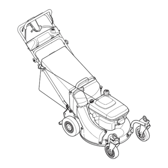
Model E997 shown.
21" Self-Propelled Mower — Model Series 900
IMPORTANT:
READ SAFETY RULES AND INSTRUCTIONS
CAREFULLY BEFORE OPERATING EQUIPMENT.
769-03045
MTD Products Ltd., P. O. Box 1386, KITCHENER, ONTARIO N2G
PRINTED IN U.S.A.
1/4/07
Advertisement

Related Manuals for Troy-Bilt E997


Summary of Contents for Troy-Bilt E997
- Page 1 Safety • Set-Up • Operation • Adjustments • Maintenance • Troubleshooting • Parts Lists • Warranty OPERATOR’S MANUAL Model E997 shown. 21” Self-Propelled Mower — Model Series 900 IMPORTANT: READ SAFETY RULES AND INSTRUCTIONS CAREFULLY BEFORE OPERATING EQUIPMENT. 769-03045 MTD Products Ltd., P. O. Box 1386, KITCHENER, ONTARIO N2G PRINTED IN U.S.A.
-
Page 2: Table Of Contents
This Operator’s Manual is an important part of your new equipment. It will help you assemble, prepare and maintain the unit for best performance. Please read and understand what it says. Table of Contents Slope Gauge............3 Maintenance & Off-Season Storage ....10 Safe Operation Practices ........ -
Page 3: Slope Gauge
Use this page as a guide to determine slopes where you may not operate safely. Do not operate your lawn mower on such slopes. Slope Gauge WARNING Do not mow on inclines with a slope in excess of 15 degrees (a rise of approximately 2-1/2 feet every 10 feet). -
Page 4: Safe Operation Practices
WARNING: Engine Exhaust, some of its constituents, and certain vehicle components contain or emit chemicals known to State of California to cause cancer and birth defects or other reproduc- tive harm. DANGER: This machine was built to be operated according to the rules for safe operation in this manual. As with any type of power equipment, carelessness or error on the part of the operator can result in serious injury. - Page 5 8. Never fuel machine indoors because flammable vapors will accumulate in the area. 1. Mow across the face of slopes; never up and down. Exercise extreme caution when changing direction on 9. Never remove gas cap or add fuel while the engine is slopes.
-
Page 6: Set-Up & Adjustments
NOTE: This owner’s manual covers various models of lawnmowers. The units illustrated may vary slightly from your unit. Follow only those instructions which pertain to your model lawnmower. 1. Remove loose parts and any packing material which may be between upper and lower handles. Pull up and back on the upper handle to raise the handle from position A. - Page 7 5. Bagging Grass Clippings. a. Remove wing nuts holding mulching plug (see Figure 4) or side discharge chute (see Figure 5) in place. Then remove baffle or discharge chute. b. Replace with bagging adapter (see Figure 6). Attach using wing nuts. Be sure that inner lip of Setup and attachment goes under the edge of the deck.
-
Page 8: Operation
Know Your Lawn Mower Electric Starter Blade Contro (If Equipped) The ignition switch is located Electric Start on the left side of the electric Drive Control Operating starter handle panel. It is nec- essary to charge the battery Your Lawn Shift Lever for 8 to 10 hours before initial use. - Page 9 This lever is used to select the operating speed of the mower. Release the drive clutch control when changing speeds. To Stop Engine 1. Release the blade control handle to stop the engine and blade. Operating WARNING: The blade continues to rotate for a few seconds after the engine is shut Your Lawn off.
-
Page 10: Maintenance & Off-Season Storage
NOTE: This spark ignition system meets all require- ments of the Canadian Interference-Causing Equipment Regulations. 5. Clean the engine regularly with a cloth or brush. Keep the cooling system (blower housing area) clean to permit proper air circulation which is essential to engine performance and life. - Page 11 Blade Care Periodically inspect the blade adapter for cracks, especially if you strike a foreign object. Replace when necessary. Follow the steps below for blade service: 1. Remove the bolt and the blade bell support which hold the blade and the blade adapter to the engine Maintenance crankshaft.
- Page 12 10. Using a pair of pliers, pull back and rotate belt keeper bracket from the slot on idler pulley. 11. Slide the belt out from between the belt keeper bracket and the idler pulley. See Figure 16. 12. Squeeze the belt together and push belt forward. Press the control arm inward towards the deck and Maintenance remove the six speed cable from the slot.
- Page 13 25. Lightly lubricate the crankshaft and reinstall blade and blade adapter as described in the “Cutting Blade” section. 26. Tip the mower back on its wheels. 27. Make certain to retest the unit for neutral as instructed Maintenance in the Operation Section. Replacing Battery WARNING: Batteries contain sulfuric acid which may cause burns.
- Page 14 3. After charging, disconnect charger plug from outlet first, then disconnect charger lead from battery. IMPORTANT: Always plug charger lead into battery pack lead first, and then insert battery charger plug into 120 volt standard household outlet. Follow this order of Maintenance action every time you charge the battery.
-
Page 15: Trouble Shooting
Problem Cause Remedy 1. Engage blade control handle. Engine fails to start 1. Blade control handle disengaged. 2. Connect wire to spark plug. 2. Spark plug wire disconnected. 3. Fill tank with clean, fresh gasoline. 3. Fuel tank empty or stale fuel. 4. -
Page 16: Warranty
FOUR YEAR SUPREME WARRANTY: For four years from date of retail purchase within Canada, MTD PRODUCTS LIMITED will, at its option, repair or replace, for the original purchaser, free of charge, any part or parts found to be defective in material or workmanship. This warranty covers units which have Warranty been operated and maintained in accordance with the owner’s instructions furnished with the unit, and which have not been subject to misuse, abuse, commercial use, neglect, accident... -
Page 17: Illustrated Parts Lists
Parts List Pièces détachées For parts and/or accessories refer to customer support on page 2. Adressez-vous au «Service après-vente» PART à la page 2 pour ce qui N° DE N° DE concerne les pièces RÉF PIÈCE DE SCRIP TION DE SCRIP TION et/ou accessoires. - Page 18 � �...
- Page 19 PART N° DE N° DE RÉF PIÈCE DE SCRIP TION DE SCRIP TION 710-1174 Carriage Bolt 5/16-18 x 2.0 Boulon ordi naire 5/16-18 x 2,0 714-0104 Int. Cotter Pin 5/16 DIA Goupille fendue 5/16 DIA. 720-04072 Plas tic Knob Bouton en plastique Parts List 726-0240 Ca ble Tie...
- Page 20 For models with front wheel casters. Pour modèles avec roulettes pivotantes avant.
- Page 21 PART N° DE N° DE RÉF PIÈCE DE SCRIP TION DE SCRIP TION 638-0012 Axle Ass’y 20T x 21.46" Lg. Essieu 20 dents x 21,46 po de lg. 682-7526 Trans Axle Ass’y Essieu 782-7528 Chain Cover Ass’y Couvercle de la chaîne 710-0604A Hex Wash HD Scr 5/16-18 x .62 Vis taraudée 5/16-18 x 0,62...
- Page 22 PART N° DE N° DE RÉF PIÈCE DE SCRIP TION DE SCRIP TION 682-9020A RH Caster Ass’y Roulette pivotante - droit 682-9021A LH Caster Ass’y Roulette pivotante - gauche 682-9026 Wheel Caster Brkt Ass’y LH Support de rou lette Parts List 710-0260A Carriage Bolt 5/16 x 18 x .62"...
- Page 23 Parts List Pièces détachées For parts and/or accessories refer to TRANS MIS SION 618-0263A customer support on page 2. PART Adressez-vous au N° DE N° DE RÉF PIÈCE DE SCRIP TION DE SCRIP TION «Service après- 712-3025 Hex Jam Nut 5/16-24 Écrou blocage à...
- Page 24 For models without front wheel casters./Pour modèles sans roulettes pivotantes avant. Transmission and pulley for reference only./Transmission et poulie illustrées à titre de référence seulement. Pulley assembly for reference only./ Poulie illustrée à titre de référence seulement.
- Page 25 PART N° DE N° DE RÉF PIÈCE DE SCRIP TION DE SCRIP TION 638-0012 Axle Ass’y 20T x 21.46" Lg. Essieu 20 dents x 21,46 po de lg. 682-0531 Pivot Arm Ass’y Bras du pivot 682-7526 Trans Axle Ass’y Essieu 682-7528 Chain Cover Couvercle de chaîne...
- Page 26 PART N° DE N° DE RÉF PIÈCE DE SCRIP TION DE SCRIP TION 754-0460 V-Belt 3/8 x 39.24" Lg. Courroie trapézoïdale 3/8 x 39,24 po de lg 812-00251 Pul ley (6 speed ac tu a tor) Poulie 611-0064 Axle Ass’y Essieu 710-1241 Hex Wash.
- Page 27 Parts List Pièces détachées For parts and/or accessories refer to customer support on page 2. Adressez-vous au PART «Service après- vente» à la page 2 N° DE N° DE RÉF PIÈCE DE SCRIP TION DE SCRIP TION pour ce qui concerne les pièces et/ou 749-004354 Up per Han dle...