Table of Contents

Related Manuals for Toro TimeCutter 77503


Summary of Contents for Toro TimeCutter 77503
- Page 1 Operator’s Manual TimeCutter® Max or MyRIDE 54in Zero Turn Riding Mower Model—Serial Range 77503—400000000 and Up 77504—400000000 and Up 77601—400000000 and Up 77603—400000000 and Up *3464-625* A 3464-625A Original Instructions (EN)
-
Page 2: Table Of Contents
Chapter 3: Product Overview ......................3–1 Control Panel............................. 3–2 Motion-Control Levers........................3–3 Park Position ..........................3–3 MyRide® Suspension Adjustment Lever ..................3–4 © 2023—The Toro ® Company Contact us at www.Toro.com 8111 Lyndale Ave So Printed in the USA Bloomington, MN 55044 All rights reserved... - Page 3 Height-of-Cut Pin ..........................3–4 Deck-Lift Pedal..........................3–4 Specifications ............................ 3–4 Chapter 4: Operation ........................... 4–1 Before Operation ..........................4–1 Before Operation Safety ......................4–1 Fuel ..............................4–3 Performing Daily Maintenance ....................4–3 Break-In Time ..........................4–4 Safety-Interlock System......................4–4 Positioning the Seat ........................4–5 Adjusting the Motion-Control Lever Height ................
- Page 4 Inspecting the Belts........................5–22 Replacing the Mower Belt......................5–22 Mower-Deck Maintenance ......................5–24 Blade Safety ..........................5–24 Blade Service ..........................5–24 Leveling the Mower Deck ......................5–27 Removing the Mower Deck ...................... 5–29 Installing the Mower Deck ......................5–30 Replacing the Grass Deflector ....................5–30 Cleaning............................
-
Page 5: Chapter 1: Introduction
Whenever you need service, genuine Toro parts, or additional information, contact an Authorized Service Dealer or Toro Customer Service and have the model and serial numbers of your product ready. These numbers are located on the serial plate on your product . -
Page 6: Manual Conventions
Manual Conventions This manual identifies potential hazards and has safety messages identified by the safety- alert symbol, which signals a hazard that may cause serious injury or death if you do not follow the recommended precautions. G405934 This manual uses 2 words to highlight information. Important calls attention to special mechanical information and Note emphasizes general information worthy of special attention. -
Page 7: Chapter 2: Safety
Chapter 2 Safety General Safety This product is capable of amputating hands and feet and of throwing objects. Always follow all safety instructions to avoid serious personal injury or death. • Read, understand, and follow the instructions and warnings in this Operator’s Manual and on the machine, engine, and attachments before starting the engine. -
Page 8: Slope Indicator
Slope Indicator You may copy this page for personal use. G011841s The maximum slope you can operate the machine on is 15 degrees. Use the slope chart to determine the degree of slope of hills before operating. Do not operate this machine on a slope greater than 15 degrees. Fold along the appropriate line to match the recommended slope. -
Page 9: Safety And Instructional Decals
Safety and Instructional Decals Safety decals and instructions are easily visible to the operator and are located near any area of potential danger. Replace any decal that is damaged or missing. Decal Part: 99-3943 Belt routing Engine s_decal99-3943 Decal Part: 112-9840 Read the Operator's Manual. - Page 10 Decal Part: 132-0872 Thrown object hazard—keep bystanders away. Thrown object hazard, mower—do not operate the machine with an open deck; use a bagger or a deflector. Cutting/dismemberment hazard of hands or feet, mower blade—stay away from moving parts. Entanglement hazard of hands, belt—stay away from moving parts;...
- Page 11 Decal Part: 144-5288 Warning—read the Operator’s Manual. Cutting/dismemberment hazard of the fingers or hand—keep hands away from moving parts; keep all guards and shields in place. Thrown object hazard—keep bystanders away; pick up debris; keep the deflector in place. Runover hazard—do not carry passengers;...
- Page 12 Decal Part: 147-2866 Height of cut decal147-2866 Decal Part: 147-7571 Fast Slow s_decal147-7571 Decal Part: 147-7574 MyRIDE models only s_decal147-7574 Safety: Safety and Instructional Decals Page 2–6 3464-625 A...
- Page 13 Decal Part: 161-6207 Bypass lever position for pushing the machine Bypass lever position for operating the machine decal161-6207 3464-625A Page 2–7 Safety: Safety and Instructional Decals...
-
Page 14: Chapter 3: Product Overview
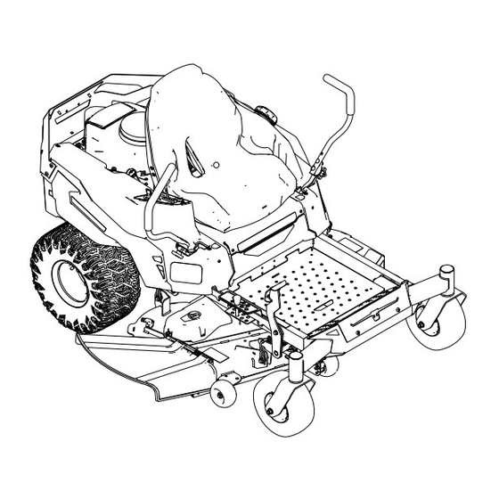
Chapter 3 Product Overview G454341 Engine Deflector Front caster wheel Height-of-cut pin Motion-control lever MyRide® suspension adjustment lever (machines Fuel-tank cap Deck-lift pedal with MyRide suspension only) Anti-scalp roller Control panel Product Overview Page 3–1 3464-625 A... -
Page 15: Control Panel
Control Panel Throttle control Choke control Key switch Blade-control switch (power takeoff) G450844 Key Switch Use the key switch to start or shut off the machine. Shut off the engine Run the engine Start engine G375755s Throttle Control The throttle controls the engine speed, and it has a continuous-variable setting from the to F position. -
Page 16: Motion-Control Levers
Blade-Control (PTO) Switch The blade-control switch, represented by a power- takeoff (PTO) symbol, engages and disengages power to the mower blades. G428617 Choke Control Use the choke control to aid in starting a cold engine. G419508 Disengaged Engaged Motion-Control Levers Use the motion-control levers to drive the machine forward, reverse, and turn either direction. -
Page 17: Myride® Suspension Adjustment Lever
MyRide® Suspension Adjustment Lever For Machines with the MyRide Suspension System Use the adjustment lever to adjust the seat suspension for a smooth and comfortable ride. Adjustment lever Softer suspension Firmer suspension G292102s Height-of-Cut Pin The height-of-cut pin works with the foot pedal to lock the deck in a specific cutting height. Adjust the height of cut only when the machine is not moving. - Page 18 Attachments/Accessories A selection of Toro approved attachments and accessories is available for use with the machine to enhance and expand its capabilities. Contact your Authorized Service Dealer or authorized Toro distributor or go to www.Toro.com for a list of all approved attachments and accessories.
-
Page 19: Chapter 4: Operation
Chapter 4 Operation Before Operation Before Operation Safety • Do not allow children or untrained people to operate or service the machine. Local regulations may restrict the age of the operator. The owner is responsible for training all operators and mechanics. •... - Page 20 Before Operation Safety (continued) Fuel Safety • Fuel is extremely flammable and highly explosive. A fire or explosion from fuel can burn you and others and can damage property. – To prevent a static charge from igniting the fuel, place the container and/or machine directly on the ground before filling, not in a vehicle or on an object.
-
Page 21: Fuel
Fuel Fuel Specifications Capacity 19 L (5 US gallons) Type Unleaded gasoline Minimum octane rating 87 (US) or 91 (research octane; outside the US) Ethanol No more than 10% by volume Methanol None MTBE (methyl tertiary butyl ether) Less than 15% by volume Do not add to the fuel Use only clean, fresh (no more than 30 days old), fuel from a reputable source. -
Page 22: Break-In Time
Break-In Time New engines take time to develop full power. Mower decks and drive systems have higher friction when new, placing additional load on the engine. Allow 40 to 50 hours of break-in time for new machines to develop full power and best performance. Safety-Interlock System The safety-interlock system is designed to prevent the engine from starting unless: •... -
Page 23: Positioning The Seat
Safety-Interlock System (continued) 3. Sit on the seat, move the blade-control switch to the O position, and move the motion- control levers to the P position. Start the engine. While the engine is running, engage the blade-control switch, and rise slightly from the seat; the engine should shut off within 1 second. -
Page 24: Adjusting The Motion-Control Lever Height
Positioning the Seat (continued) Machines without MyRide Suspension G293874s Adjusting the Motion-Control Lever Height Adjust the motion-control levers higher or lower for your comfort. G450938 Operation: Before Operation Page 4–6 3464-625 A... -
Page 25: Adjusting The Motion-Control Lever Tilt
• Do not operate the machine unless all guards and safety devices, such as the deflectors and the entire grass catcher, are in place and functioning properly. Replace worn or deteriorated parts with genuine Toro parts when necessary. • Operating engine parts, especially the muffler, can become extremely hot. Severe burns can occur on contact and debris, such as leaves, grass, brush, etc. - Page 26 • Do not use the machine as a towing vehicle unless it has a hitch installed. Attach towed equipment to the machine only at the hitch point. • Use only accessories and attachments approved by The Toro® Company. Slope Safety •...
- Page 27 During Operation Safety (continued) – Use an angle indicator to determine the approximate slope angle of the area. – Never operate on slopes greater than 15°. – Evaluate the site conditions of the day to determine if the slope is safe for machine operation.
-
Page 28: Starting The Engine
During Operation Safety (continued) Towing Safety • Do not attach towed equipment except at the hitch point. • Do not use the machine as a towing vehicle unless it has a hitch installed. • Do not exceed the maximum gross towing weight. •... -
Page 29: Shutting Off The Engine
Shutting Off the Engine 1. Disengage the blades by moving the blade- control switch to the O position. 2. Move the motion-control levers outward to the position. 3. Move the throttle control to the S position and let the engine idle for 1 minute. 4. -
Page 30: Driving The Machine
Driving the Machine CAUTION Positioning one lever too far in front of the other causes the machine to spin very rapidly. As a result, you may lose control of the machine, causing personal injury to you and damage to the machine. Slow down the machine before making sharp turns. -
Page 31: Operating The Mower Blade-Control Switch (Pto)
Driving the Machine (continued) 2. Slowly push the motion-control levers forward or rearward. Move 1 lever farther than the other lever to turn. Note: The farther you move the motion- control levers, the faster the machine moves in that direction. 3. -
Page 32: Side Discharge
Operating the Mower Blade-Control Switch (PTO) (continued) 2. Engage the blade-control switch. G450387 3. Mow as desired. 4. Disengage the blade-control switch. G450388 Side Discharge The hinged grass deflector disperses clippings to the side and down toward the turf. DANGER Without the grass deflector, discharge cover, or complete grass catcher assembly mounted in place, you and bystanders are exposed to blade contact and thrown debris. -
Page 33: Adjusting The Height Of Cut
Adjusting the Height of Cut You can adjust the height of cut from 38 to 127 mm (1-1/2 to 5 inches) in 13 mm (1/2 inch) increments. 1. Push the deck-lift pedal with your foot to raise the mower deck. 2. - Page 34 Operating Tips (continued) Avoid Cutting Too Low When mowing uneven ground, raise the cutting height to slightly higher than normal to avoid scalping the turf. However, the cutting height used in the past is generally the best one to use. When cutting grass longer than 15 cm (6 inches) tall, you may want to cut the lawn twice to ensure an acceptable quality of cut.
-
Page 35: After Operation
After Operation After Operation Safety • Park the machine on a level surface, disengage the drives, engage the parking brake, shut off the engine, remove the key, and wait for all moving parts to stop before leaving the operator’s position. •... - Page 36 Hauling the Machine (continued) Trailer Requirements WARNING Loading a machine onto a trailer or truck increases the possibility of tip-over and could cause serious injury or death. • Use only a full-width ramp; do not use individual ramps for each side of the machine.
- Page 37 Hauling the Machine (continued) Loading the Machine WARNING Loading a machine onto a trailer or truck increases the possibility of tip-over and could cause serious injury or death. • Use extreme caution when operating a machine on a ramp. • Back the machine up the ramp and drive it forward down the ramp. •...
-
Page 38: Chapter 5: Maintenance
Removing or modifying original equipment, parts, and/or accessories may alter the warranty, controllability, and safety of the machine. Making unauthorized modifications to the original equipment or failing to use original Toro parts could lead to serious injury or death. • Check the parking brake operation frequently. Adjust and service it as required. -
Page 39: Recommended Maintenance Schedule
• To ensure optimum performance, use only genuine Toro replacement parts and accessories. Replacement parts and accessories made by other manufacturers could be dangerous. Recommended Maintenance Schedule Maintenance Maintenance Procedure Service Interval After the first 8 hours Change the engine oil. -
Page 40: Pre-Maintenance Procedures
Pre-Maintenance Procedures Moving a Non-Functioning Machine 1. Park the machine on a level surface, disengage the blade-control switch, and move the motion-control levers outward to the P position. 2. Shut off the engine and wait for all moving parts to stop before leaving the operating position. -
Page 41: Raising The Machine
Moving a Non-Functioning Machine (continued) 5. Disengage the parking brake by moving both motion-control levers down to the center, unlocked position. Note: Do not start the machine. 6. Move the machine as required. IMPORTANT Always push the machine by hand. Do not tow the machine, because towing may damage it. -
Page 42: Lubrication
Lubrication Greasing the Bearings 1. Park the machine on a level surface, disengage the blade-control switch, and move the motion-control levers outward to the P position. 2. Shut off the engine and wait for all moving parts to stop before leaving the operating position. -
Page 43: Engine Maintenance
Engine Maintenance Engine Safety • Keep your hands, feet, face, other body parts, and clothing away from the muffler and other hot surfaces. Wait for the engine to cool before performing maintenance. • Do not change the engine governor speed or overspeed the engine. Air Cleaner Service Removing the Air-Cleaner Element 1. -
Page 44: Engine-Oil Service
Air Cleaner Service (continued) Installing the Air-Cleaner Element 1. Install the air-cleaner element onto the air- cleaner base. 2. Install the cover and tighten the hose clamp G207139s Engine-Oil Service Engine-Oil Specifications Oil Type Detergent oil (API service SF, SG, SH, SJ, or Crankcase Capacity 1.8 L (61 fl oz);... - Page 45 Engine-Oil Service (continued) Checking the Engine-Oil Level 1. Park the machine on a level surface, disengage the blade-control switch, and move the motion-control levers outward to the P position. 2. Shut off the engine, remove the key, and wait for all moving parts to stop before leaving the operating position.
- Page 46 Engine-Oil Service (continued) Changing the Engine Oil 1. Park the machine so that the drain side is slightly lower than the opposite side to ensure that the oil drains completely. 2. Disengage the blade-control switch (PTO) and move the motion-control levers outward to the P position.
- Page 47 Engine-Oil Service (continued) Changing the Engine-Oil Filter 1. Drain the oil from the engine. 2. Change the engine-oil filter as shown. Note: Ensure that the oil-filter gasket touches the engine, and then turn the oil filter an extra 3/4 turn. G398545s 3.
-
Page 48: Servicing The Spark Plug
Servicing the Spark Plug Ensure that the air gap between the center and side electrodes is correct before installing the spark plug. Use a spark plug wrench for removing and installing the spark plug and a gapping tool or feeler gauge to check and adjust the air gap. Install a new spark plug if necessary. -
Page 49: Cleaning The Cooling System
Servicing the Spark Plug (continued) Installing the Spark Plug g027661s Cleaning the Cooling System 1. Park the machine on a level surface, disengage the blade-control switch, and move the motion-control levers outward to the P position. 2. Shut off the engine, remove the key, and wait for all moving parts to stop before leaving the operating position. -
Page 50: Fuel Maintenance
Fuel Maintenance DANGER In certain conditions, fuel is extremely flammable and highly explosive. A fire or explosion from fuel can burn you and others and can damage property. Refer to Fuel Safety, page 4–2 for a complete list of fuel related precautions. Replacing the Fuel Filter 1. -
Page 51: Electrical System Maintenance
Electrical System Maintenance Electrical System Safety • Disconnect the cable from the negative terminal of the battery before repairing the machine. • Charge the battery in an open, well-ventilated area, away from sparks and flames. Unplug the charger before connecting or disconnecting the battery. Wear protective clothing and use insulated tools. - Page 52 Battery Service (continued) 5. Disconnect the positive (red) cable from the battery post (+). Note: Retain all fasteners. 6. Remove the battery hold-down and lift the battery from the battery tray. G440221 Battery hold-down Battery Bolt, washer, and nut Terminal boot Negative (–) battery post Positive (+) battery post Wing nut, washer, and bolt...
- Page 53 Battery Service (continued) IMPORTANT Do not overcharge the battery; otherwise, you could damage it. Positive battery post Negative battery post Red (+) charger lead Black (-) charger lead G003792S 3. When the battery is fully charged, unplug the charger from the electrical outlet (if applicable), then disconnect the charger leads from the battery posts.
- Page 54 Battery Service (continued) Installing the Battery 1. Position the battery in the tray. 2. Using the fasteners previously removed, install the positive (red) battery cable to the positive (+) battery terminal. 3. Using the fasteners previously removed, install the negative battery cable to the negative (-) battery terminal.
-
Page 55: Jump-Starting The Machine
Jump-Starting the Machine WARNING Jump-starting the battery can produce gasses that can explode. Do not smoke near the battery, and keep sparks and flames away from battery. DANGER Jump-starting a weak battery that is cracked or frozen or has a low electrolyte level or an open/shorted battery cell can cause an explosion, resulting in serious personal injury. - Page 56 Jump-Starting the Machine (continued) Positive (+) cable on discharged battery Positive (+) cable on booster battery Negative (–) cable on the booster battery Negative (–) cable on the engine block Booster battery Discharged battery g012785 Engine block 4. Connect the other end of the positive (+) jumper cable to the positive terminal of the battery in the other machine.
-
Page 57: Servicing The Fuses
Servicing the Fuses The electrical system is protected by fuses. It requires no maintenance; however, if a fuse blows, check the component/circuit for a malfunction or short. 1. Park the machine on a level surface, disengage the blade-control switch, and move the motion-control levers outward to the P position. -
Page 58: Checking The Wheel Lug Nuts
Checking the Wheel Lug Nuts Check and torque the wheel lug nuts to 108 N∙m (80 ft-lb). Adjusting the Tracking When driving the machine forward full speed across a flat, level surface, if the machine pulls to 1 side, adjust the tracking. If the machine pulls to the left, adjust the right motion-control lever;... -
Page 59: Belt Maintenance
Belt Maintenance Inspecting the Belts 1. Park the machine on a level surface, disengage the blade-control switch, and move the motion-control levers outward to the P position. 2. Shut off the engine and wait for all moving parts to stop before leaving the operating position. - Page 60 Wire form Idler pulley G336421s 6. Using a spring-removal too (Toro Part No. 92-5771), remove the idler spring from the deck hook to remove tension on the idler pulley. WARNING The spring is under tension when installed and can cause personal injury.
-
Page 61: Mower-Deck Maintenance
Replacing the Mower Belt (continued) 9. Use the spring-removal tool to install the idler spring over the deck hook and place tension on the idler pulley and the mower belt. 10. Tighten the nut securing the wire form to the idler pulley. Note: Position the wire form against the idler arm. - Page 62 Blade Service (continued) Checking for Bent Blades The machine must be on a level surface for this procedure. 1. Raise the mower deck to the highest height-of-cut position. 2. While wearing thickly padded gloves, or other adequate hand protection, slowly rotate the blade into a position that allows you to measure the distance between the cutting edge and the level surface.
- Page 63 Blade Service (continued) 6. If the difference between A and B is greater than 3 mm (1/8 inch), replace the blade. Note: If you replace the blade and the difference continues to exceed 3 mm (1/8 inch), the blade spindle could be bent. Contact an Authorized Service Dealer for service. 7.
-
Page 64: Leveling The Mower Deck
WARNING Operating a machine after incorrectly installing the blade assembly and/or not using genuine Toro blade and blade hardware could allow a blade or blade component to be thrown out from under the deck, resulting in serious injury or death. - Page 65 Leveling the Mower Deck (continued) Checking the Mower-Deck Level 1. Position the blades side-to-side. 2. Measure at locations from a level surface to the cutting edge of the blade tips The difference between the measurements should be no more than 5 mm (3/16 inch). If the measurement is larger, adjust the side-to- side level.
-
Page 66: Removing The Mower Deck
Leveling the Mower Deck (continued) IMPORTANT Do not place the blocks under the anti-scalp roller brackets. 4. Place 2 blocks , each having a thickness of 7.3 cm (2-7/8 inches), under each side of the rear edge of the deck. 5. -
Page 67: Installing The Mower Deck
Installing the Mower Deck 1. Park the machine on a level surface, disengage the blade-control switch, and move the motion-control levers outward to the P position. 2. Shut off the engine, remove the key, and wait for all moving parts to stop before leaving the operating position. -
Page 68: Cleaning
Replacing the Grass Deflector (continued) Mower deck Grass-deflector pivot Grass deflector Spring G451625 4. Slide the rod out. 5. Remove the damaged or worn grass deflector. 6. Install the new grass deflector. 7. Slide the straight end of the rod through the rear grass deflector pivot. 8. -
Page 69: Disposing Of Waste
Washing the Underside of the Mower Deck (continued) Wash the underside of the mower deck after each use to prevent grass buildup for improved mulch action and clipping dispersal. 1. Park the machine on a level surface, disengage the blade-control switch (PTO), and move the motion-control levers outward to the P position. -
Page 70: Chapter 6: Storage
Chapter 6 Storage Storage Safety • Park the machine on a level surface, disengage the drives, engage the parking brake, shut off the engine, remove the key, and wait for all moving parts to stop before leaving the operator’s position. •... - Page 71 6. Check the tire pressure. 7. Charge the battery. 8. Check the condition of the cutting blades. 9. Prepare the fuel system. A. Add a petroleum-based fuel stabilizer/conditioner to the fuel in the tank. Do not use an alcohol-based stabilizer (ethanol or methanol). B.
-
Page 72: Storing The Battery
Storing the Battery Note: Follow the tips below to properly store the battery. • If you are storing the machine for more than 30 days, remove the battery and charge it fully. • Store it either on the shelf or on the machine. •... -
Page 73: Chapter 7: Troubleshooting
Chapter 7 Troubleshooting The fuel tank is showing signs of collapsing or the machine is frequently showing signs of running out of fuel. Possible Cause Corrective Action The air-cleaner paper element clogged. Clean the paper element. The engine overheats. Possible Cause Corrective Action The engine load is excessive. - Page 74 The engine does not start, starts hard, or fails to keep running. Possible Cause Corrective Action The fuel tank is empty. Fill the fuel tank. The choke (if applicable) is not on. Move the choke lever to the position. The air cleaner is dirty. Clean or replace the air-cleaner element.
- Page 75 The machine does not drive. Possible Cause Corrective Action The bypass valves are open. Close the tow valves. The traction belts are worn, loose, or Contact an Authorized Service Dealer. broken. The traction belts are off the pulleys. Contact an Authorized Service Dealer. The transmission has failed.
- Page 76 The blades do not rotate. Possible Cause Corrective Action The drive belt is worn, loose or broken. Install a new drive belt. The drive belt is off of the pulley. Install the drive belt and check the adjusting shafts and belt guides for the correct position.
- Page 77 Chapter 8 Schematics Electrical Diagram G454156 3464-625 A Page 8–1 Schematics...
-
Page 78: California Proposition 65 Warning Information
Toro has chosen to provide consumers with as much information as possible so that they can make informed decisions about the products they buy and use. Toro provides warnings in certain cases based on its knowledge of the presence of one or more listed chemicals without evaluating the level of exposure, as not all the listed chemicals provide exposure limit requirements. - Page 79 Notes:...