Table of Contents
Advertisement
Introduction
U N P A C K I N G
Congratulations on Your Purchase!
Your new high fidelity receiver is designed to deliver
maximum enjoyment and years of trouble free service.
Please take a few moments to read this manual
thoroughly. It will explain the features and operation of
your unit and help ensure a trouble free installation.
Please unpack your unit carefully. We recommend that
you save the carton and packing material. They will be
helpful if you ever need to move your unit and may be
required if you ever need to return it for service. Your unit
is designed to be placed in a horizontal position and it is
important to allow at least two inches of space behind
your unit for adequate ventilation and cabling
convenience.
To avoid damage, never place the unit near radiators, in
front of heating vents, in direct sunlight, or in excessively
humid or dusty locations. Connect your complementary
components as illustrated in the following section.
CAUTION
RISK OF ELECTRIC SHOCK
DO NOT OPEN
CAUTION : TO REDUCE THE RISK OF
ELECTRIC SHOCK, DO NOT
REMOVE COVER (OR BACK).
NO USER-SERVICEABLE PARTS
INSIDE. REFER SERVICING TO
QUALIFIED SERVICE PERSONNEL.
This symbol is intended to alert the user to the
presence of uninsulated "dangerous voltage"
within the product's enclosure that may be of
sufficient magnitude to constitute a risk of
electric shock to persons.
This symbol is intended to alert the user to the
presence of important operating and
maintenance (servicing) instructions in the
literature accompanying the appliance.
WARNING
To reduce the risk of fire or electric shock, do not expose
this appliance to rain or moisture.
Caution : Do not block ventilation openings or stack
other equipment on the top.
A N D
FOR U.S.A
Note to CATV System Installer: This reminder is
provided to call the CATV system installer's attention
to Article 820-40 of the NEC that provides guidelines
for proper grounding and, in particular, specifies that
the cable ground shall be connected to the
grounding system of the building, as close to the
point of cable entry as practical.
FCC INFORMATION
This equipment has been tested and found to
comply with the limits for a Class B digital device,
pursuant to Part 15 of the FCC Rules. These limits
are designed to provide reasonable protection
against harmful interference in a residential
installation. This equipment generates, uses and can
radiate radio frequency energy and, if not installed
and used in accordance with the instructions, may
cause harmful interference to radio communications.
However, there is no guarantee that interference will
not occur in a particular installation. If this equipment
does cause harmful interference to radio or
television reception, which can be determined by
turning the equipment off and on, the user is
encouraged to try to correct the interference by one
or more of the following measures:
Reorient or relocate the receiving antenna.
Increase the separation between the equipment
and receiver.
Connect the equipment into an outlet on a circuit
different from that to which the receiver is
connected.
Consult the dealer or an experienced radio/TV
technician for help.
CAUTION: Any changes or modifications in
construction of this device which are not expressly
approved by the party responsible for compliance
could void the user's authority to operate the
equipment.
Caution regarding placement
(Except for U.S.A and Canada)
To maintain proper ventilation, be sure
to leave a space around the unit (from
the largest outer dimensions including projections)
equal to, or greater than, shown below.
Left and right panels: 5 cm
Rear panel: 5 cm
Top panel: 20 cm
2
Advertisement
Table of Contents

Related Manuals for Sherwood RD-8108


Summary of Contents for Sherwood RD-8108
-
Page 1: Unpacking And Installation
Introduction U N P A C K I N G Congratulations on Your Purchase! Your new high fidelity receiver is designed to deliver maximum enjoyment and years of trouble free service. Please take a few moments to read this manual thoroughly. -
Page 2: Read This Before Operating Your Unit
READ THIS BEFORE OPERATING FOR U.S.A AND CANADA ... 120 V FOR YOUR SAFETY Units shipped to the U.S.A and Canada are designed for operation on 120 V AC only. Safety precaution with use of a polarized AC plug. However, some products may be supplied with a nonpolarized plug. -
Page 3: Table Of Contents
CONTENTS Introduction • UNPACKING AND INSTALLATION ... 2 • READ THIS BEFORE OPERATING YOUR UNIT... 3 System Connections ... 5 Front Panel Controls ... 8 Universal Remote Controls ... 9 • OPERATING COMPONENTS WITH REMOTE CONTROL... 11 • REMOTE CONTROL OPERATION RANGE ... 11 •... -
Page 4: System Connections
• Be sure to observe the color coding when connecting audio and video cords. • Make connections firmly and correctly. If not, it can cause loss of sound, noise or damage to the receiver. • If the electricity fails or the AC input cord is left unplugged for more than 2 weeks, the memorized contents will be cleared. - Page 5 Note : • When Sherwood DVD player such as V-756, etc. is connected to the DIGI LINK jack for system control, you should connect the DVD player to the “VIDEO 2” jacks of this unit. Because if the PLAY button, etc. is pressed on the DVD player, the “VIDEO 2”...
-
Page 6: Connecting Speakers
6 . CONNECTING DIGITAL INs and O U T • The COAXIAL or the OPTICAL DIGITAL OUTs of the components that are connected to CD and VIDEO 1~3 of this unit can be connected to these DIGITAL INs. • If a digital recorder or other component with OPTICAL DIGITAL IN/OUT jacks is connected to the corresponding jacks of this unit, you can playback and/or record the high quality sound of CD’s, etc. -
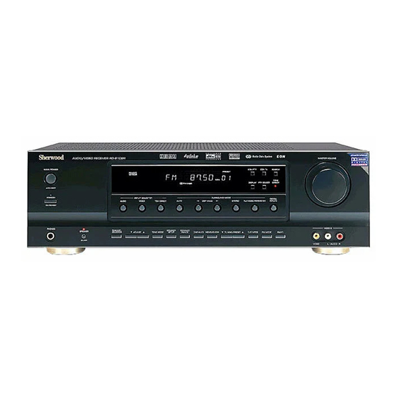
Page 7: Front Panel Controls
Front Panel Controls 25 24 23 22 AUDIO/VIDEO RECEIVER RD-8108 POWER STANDBY ON/STANDBY PHONES SPEAKER ON/OFF 1. POWER switch 2. STANDBY button/indicator 3 . H E A D P H O N E jack 4. SPEAKER button/indicator 5. CHANNEL SELECTOR button 6. -
Page 8: Universal Remote Controls
(For details, refer to “USING FUNCTIONS OF REMOTE CONTROL” on page 12.) Digi link system remote controls This remote control can also operate Sherwood compatible components bearing the DIGI LINK (II or III) logo. • For digi link system remote control operation, first make the DIGI LINK connections between Sherwood components. -
Page 9: Function Table Of The Numbered Buttons
REVERSE SEARCH( )/ FAST FORWARD( ) FORWARD SEARCH( ) REVERSE SKIP( FORWARD SKIP( NUMERIC NUMERIC NUMERIC CABLE (for cable box) (for satellite receiver) POWER POWER STANDBY STANDBY (POWER OFF) (POWER OFF) CHANNEL LEVEL CHANNEL LEVEL UP/DOWN( / ) UP/DOWN( / ) -
Page 10: Operating Components With Remote Control
SENSOR of the component you wish to control and press the button corresponding to the operation you want. • When operating a Sherwood CD player or tape deck using digi link system remote control, aim the remote control at the REMOTE SENSOR of this receiver. -
Page 11: Using Functions Of Remote Control
Sherwood CD player, “DVD” for Sherwood DVD player and “AUX” for Sherwood tape deck respectively as its factory setup code. So, you don’t need to enter its code for each Sherwood component except in such a case that its code does not work. - Page 12 TV channel punch-through in conjunction with any of the eight components controlled by this remote control. For example, since this receiver will likely be used as the sound system while watching TV, you may want to adjust this receiver’s volume although this remote control is set to control the TV.
- Page 13 VIDEO 2 jacks of this receiver. 1. Press “AUDIO” button to control this receiver. 2. Press “POWER” button to turn this receiver on. 3. Press “AUDIO” button to control this receiver. 4. Press “VIDEO 2(7)” button to select the desired input source.
-
Page 14: Operations
Operations • Note : Before operating this receiver with the supplied remote control, refer to “Universal Remote Controls” on page 9 for details about operation. L I S T E N I N G T O A P R O G R A M Before operation •... - Page 15 When CD, VIDEO 1~3 is selected as an input source Select the digital or analog input connected as desired. DIGITAL INPUTS • Each time this button is pressed, the corresponding input is selected as follows ; A(nalog) c(oaxial) 1 c(oaxial) 2 o(ptical) 2 o(ptical) 1 •...
- Page 16 Adjusting the tone(bass and treble) Enter the tone mode. TONE MODE • Each time this button is pressed, the corresponding tone mode is selected and shown for several seconds as follows: BASS TRBL(treble) TONE ON • When the tone mode is off, “TONE OFF” is shown. At the desired tone mode, adjust the tone as desired.
-
Page 17: Surround Sound
SURROUND SOUND • This receiver incorporates a sophisticated Digital Signal Processor that allows you to create optimum sound quality and sound atmosphere in your personal Home Theater. Surround modes DTS Digital Surround DTS Digital Surround(also called simply DTS) is a multi- channel digital signal format which can handle higher data rates than Dolby Digital. - Page 18 Dolby Pro Logic Dolby Pro Logic is a specially encoded two channel surround format which consists of four channels ( front left, center, front right and surround). Sources bearing the “ ” provide the theater-like surround sound. DOLBY SURROUND The surround channel is monaural, but is played through both surround speakers.
-
Page 19: Speaker Placement
Speaker placement Ideal speaker placement varies depending on the size of your room and the wall coverings, etc. The typical example of speaker placement and recommendations are as follows : Front left and right speakers and center speaker Place the front speakers with their front surfaces as flush with TV or monitor screen as possible. - Page 20 Adjusting the speaker settings • After you have installed this unit and connected all the components, you should adjust the speaker settings for the optimum sound acoustics according to your environment and speaker layout. • There are two kinds of speaker settings for speaker size and speaker distance. Speaker size settings Select the corresponding settings depending on the sizes of the connected speakers and whether the speakers are connected or not.
- Page 21 Refer to the previous page and adjust the speaker settings Note : When the SPEAKER button is set to off or the 7 CH DIRECT is selected as an input source, the speaker setting function cannot be available. When selecting each setting mode POWER AUDIO SPK SET...
-
Page 22: Enjoying Surround Sound
ENJOYING SURROUND SOUND Depending on the input digital signal format, select the desired decoding mode. POWER AUDIO AUTO SPK SET AUDIO SEL. AUTO Notes : • Only when the digital input is selected as signal input for the input sources except TUNER, TAPE and AUX, the decoding mode can be selected. - Page 23 To cancel the surround mode for stereo operation STEREO • Then the stereo mode is selected. • To cancel the stereo mode, select the desired surround mode with using the DSP MODE Adjusting the Dolby Pro Logic II Music parameters •...
- Page 24 Adjusting each channel level Select the desired channel. POWER STANDBY AUDIO CABLE MACRO CH SEL. CHANNEL SPK SET PARA. CH SEL. CH/LEVEL SELECTOR ADJUST MUTE VOLUME AUDIO SEL. SUBTITLE ZOOM AUTO STEREO T.TONE SETUP MENU ENTER SLEEP DIMMER DISPLAY RETURN P .SCAN TUNE PRESET...
- Page 25 At each channel, adjust the level as desired until the sound level of each speaker is heard to be equally loud. POWER STANDBY AUDIO CABLE MACRO SPK SET PARA. CH SEL. CH/LEVEL ADJUST ADJUST MUTE CH/LEVEL VOLUME AUDIO SEL. SUBTITLE ZOOM AUTO STEREO...
-
Page 26: Listening To Radio Broadcasts
LISTENING Auto tuning Select the tuner. POWER AUDIO AUDIO SPK SET ADJUST AUDIO SEL. AUTO SETUP TUNER SLEEP DISPLAY TUNE TUNER VIDEO1 VIDEO2 VIDEO3 UNIVERSAL REMOTE CONTROL Select the tuning mode. T/P MODE • Each time this button is pressed, the mode changes as follows;... - Page 27 TUNE TUNER VIDEO1 VIDEO2 VIDEO3 UNIVERSAL REMOTE CONTROL • The receiver will start scanning the stations in the preset sequence and each station is received for 5 seconds. • At the desired station, press this button again to stop scanning.
-
Page 28: Recording
RECORDING • The analog signals from the 7 CH DIRECT inputs as well as the digital signals from the coaxial or optical digital input can be heard but cannot be recorded. • The volume and tone (bass, treble) settings have no effect on the recording signals. Recording with TAPE Select the desired input as a recording source except for TAPE. -
Page 29: Digital Audio Recording With Md Recorder
DIGITAL AUDIO RECORDING WITH • Only when the OPTICAL DIGITAL OUT of this receiver is connected to the OPTICAL DIGITAL IN of the MD recorder or CD recorder, you can enjoy high-quality sound of digital recording without converting the original signals. -
Page 30: Other Functions
• While operating the sleep timer, “SLEEP” lights up. • When the sleep time is selected, all display panels of Sherwood components connected by the DIGI LINK III are dimly lit. • Each time this button is pressed, the mode changes and the display scrolls. -
Page 31: Using The Osd
Using the OSD This unit incorporates an OSD(On-screen display) function to provide information about basic operation of this unit and to simplify the setup procedures. The OSD function uses a monitor TV connected to this unit as a display and has two kinds of display modes such as current status display and menu screen. - Page 32 Select the desired menu using the CURSOR UP( ) or DOWN( ) button. Confirm your selection. When selecting the SPEAKER SETUP SPEAKER SETUP SUBWOOFER - YE S FRON T LARGE CENTER - LARGE SURR LARGE SURR B LARGE u p / d o wn : MOVE ENTER : SEL .
- Page 33 Select the desired menu or(and) change the condition with the corresponding buttons. Repeat the above steps 2~4 to change the conditions on other menus.
-
Page 34: Troubleshooting Guide
If a fault occurs, run through the table below before taking your receiver for repair. If the fault persists, attempt to solve it by switching the receiver off and on again. If this fails to resolve the situation, consult your dealer. Under no circumstances should you attempt to repair the receiver yourself. This could void the warranty. -
Page 35: Specifications
Specifications AMPLIFIER SECTION Power output, stereo mode, 6 Ω, THD 0.2 %, 40 Hz~20 kHz ... 2 100 W Total harmonic distortion, 6 Ω, 95 W, 1 kHz ... 0.09% Intermodulation distortion 60 Hz : 7 kHz= 4 : 1 SMPTE, 6 Ω, 95 W ... 0.1% Input sensitivity, 47 kΩ... -
Page 36: Setup Code Table
Setup Code Table A O C 005 003 Admiral 041 031 Aiko Akai Alaron Ambassador America Action A m p r o A n a m 027 047 048 049 Audiovox 030 027 014 034 Baysonic Belcor Bell & Howell 019 001 Bradford Brockwood... - Page 37 Scimitsu Scotch Scott 028 027 025 003 026 Sears 007 010 019 020 025 026 011 006 Semivox S e m p Sharp 041 021 006 Sherwood Shogun Signature Sony Soundesign 027 025 026 Squareview Starlite Supreme Sylvania 010 005...
- Page 38 Headquarter Hitachi 000 008 026 Hughes Net.Sys 014 026 Jensen K E C 005 025 K L H Kenwood 014 026 006 Kodak 004 005 Lloyd’s Logik M G A 023 009 MGN Technology 023 M T C 023 000 Magnasonic Magnavox 004 007 016 000 019...
- Page 39 Panasonic Philips 011 006 Pioneer 003 014 026 Proscan R C A Samsung Sherwood 001 012 000 018 019 020 021 022 023 025 Sony Technics Theta Digital Toshiba Y a m a h a 0 1 3 0 0 7...
- Page 40 003 000 002 012 Radio Shack Realistic Sony Star Choice Toshiba Uniden 006 005 014 AUX- Sherwood 000 (for tape deck) 035 (for MD recorder) AUX-LD D e n o n 0 0 7 Mitsubishi N A D Pioneer Sony...
- Page 41 Realistic 012 019 013 Rotel 010 019 Sansui 010 035 Sanyo Scott Sears Sharp 029 013 037 Sherwood 013 027 038 039 040 041 Sony 001 014 022 Soundesign Tascam Teac 019 018 033 013 Technics 002 031 Victor Wards...