Table of Contents
Advertisement
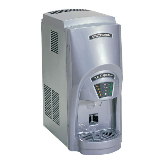
INTRODUCTION
This manual provides the specifications and the
step-by-step procedures for the installation,
start-up, operation, maintenance and cleaning for
the SCOTSMAN MDT2 counter top cubelet ice
dispenser.
SPECIFICATIONS · · · · · · · · · · · · · · · · · · · · · · · · · · · · · · · · · · · · · · · · · · · · · Page 2
CABINET DIAGRAMS
GENERAL INFORMATION AND INSTALLATION
ELECTRICAL CONNECTIONS · · · · · · · · · · · · · · · · · · · · · · · · · · · · · · · · · · · · · · Page 5
WATER SUPPLY AND DRAIN CONNECTIONS · · · · · · · · · · · · · · · · · · · · · · · · · · · · · Page 6
FINAL CHECK LIST · · · · · · · · · · · · · · · · · · · · · · · · · · · · · · · · · · · · · · · · · · · · Page 7
OPERATING INSTRUCTIONS · · · · · · · · · · · · · · · · · · · · · · · · · · · · · · · · · · · · · · Page 8
INITIAL START UP CONTINUED · · · · · · · · · · · · · · · · · · · · · · · · · · · · · · · · · · · · · Page 9
SETTING THE DISPENSING SELECTOR · · · · · · · · · · · · · · · · · · · · · · · · · · · · · · · · Page 11
PRINCIPLE OF OPERATION · · · · · · · · · · · · · · · · · · · · · · · · · · · · · · · · · · · · · · · Page 12
REFRIGERANT CIRCUIT · · · · · · · · · · · · · · · · · · · · · · · · · · · · · · · · · · · · · · · · · Page 13
MECHANICAL SYSTEM · · · · · · · · · · · · · · · · · · · · · · · · · · · · · · · · · · · · · · · · · Page 14
COMPONENT DESCRIPTION · · · · · · · · · · · · · · · · · · · · · · · · · · · · · · · · · · · · · · Page 15
COMPONENT DESCRIPTION · · · · · · · · · · · · · · · · · · · · · · · · · · · · · · · · · · · · · · Page 16
COMPONENT DESCRIPTION · · · · · · · · · · · · · · · · · · · · · · · · · · · · · · · · · · · · · · Page 17
COMPONENT DESCRIPTION · · · · · · · · · · · · · · · · · · · · · · · · · · · · · · · · · · · · · · Page 18
SERVICE DIAGNOSIS · · · · · · · · · · · · · · · · · · · · · · · · · · · · · · · · · · · · · · · · · · Page 19
SERVICE DIAGNOSIS · · · · · · · · · · · · · · · · · · · · · · · · · · · · · · · · · · · · · · · · · · Page 20
MAINTENANCE AND CLEANING INSTRUCTION · · · · · · · · · · · · · · · · · · · · · · · · · · · · Page 21
CLEANING INSTRUCTIONS OF WATER SYSTEM · · · · · · · · · · · · · · · · · · · · · · · · · · · Page 22
REMOVAL AND REPLACEMENT
TOP BEARING REPLACEMENT · · · · · · · · · · · · · · · · · · · · · · · · · · · · · · · · · · · · · Page 24
BEARING REPLACEMENT - CONTINUED · · · · · · · · · · · · · · · · · · · · · · · · · · · · · · · · Page 25
WATER SEAL · · · · · · · · · · · · · · · · · · · · · · · · · · · · · · · · · · · · · · · · · · · · · · · Page 26
Table of Contents
· · · · · · · · · · · · · · · · · · · · · · · · · · · · · · · · · · · · · · · · · · Page 3
· · · · · · · · · · · · · · · · · · · · · · · · · · · · · · · · · · · · Page 23
NOTE: To retain the safety and performance built
into this ice machine, it is important that installation
and maintenance be conducted in the manner
outlined in this manual.
· · · · · · · · · · · · · · · · · · · · · · · · · · · · Page 4
May 2002
Page 1
MDT2
Advertisement
Table of Contents

Related Manuals for Scotsman MDT2C12


Summary of Contents for Scotsman MDT2C12
- Page 1 SCOTSMAN MDT2 counter top cubelet ice dispenser. SPECIFICATIONS · · · · · · · · · · · · · · · · · · · · · · · · · · · · · · · · · · · · · · · · · · · · · Page 2 CABINET DIAGRAMS ·...
-
Page 2: Specifications
- Water temperature - Water pressure - Electrical voltage variations from voltage rating specified on nameplate To keep your SCOTSMAN CUBELET DISPENSER at peak performance levels, periodic maintenance checks must be carried out as indicated in this manual. MACHINE SPECIFICATIONS Model Cond. -
Page 3: Cabinet Diagrams
MDT2 CABINET DIAGRAMS May 2002 Page 3... -
Page 4: General Information And Installation
1. Place the unit in its final position. 2. Place a bead of sealant on the counter top to match the outside edge of the cabinet base and sink. Food grade silastic sealant such as Scotsman part number 19-0529-01 is recommended. May 2002 Page 4 50°F... -
Page 5: Electrical Connections
All SCOTSMAN ice machines require a solid earth wire. This SCOTSMAN ice machine is supplied from the factory completely pre-wired and only needs to be plugged into a nearby 115 volt outlet. -
Page 6: Water Supply And Drain Connections
MDT2 WATER SUPPLY AND DRAIN CONNECTIONS GENERAL When choosing the water supply for the ice flaker, consideration should be given to: a) Length of run b) Water clarity and purity c) Adequate water supply pressure Water is the most important single ingredient in producing ice - these three items are very important. -
Page 7: Final Check List
Check the model and serial number against the serial plate and mail the registration card to Scotsman. 11. Has the owner been given the name and the phone number of the authorized SCOTSMAN Service Agency serving them? May 2002 Page 7... -
Page 8: Operating Instructions
MDT2 OPERATING INSTRUCTIONS INITIAL START UP After having correctly installed the ice machine and completed the plumbing and electrical connections, perform the following “Start-up” procedure. Remove the control board inspection panel and cover to view the lights on the control board. A. -
Page 9: Initial Start Up Continued
INITIAL START UP CONTINUED NOTE: If the evaporating temperature has not dropped lower than 30° F within ten minutes of compressor start-up, the evaporating temperature sensor will detect the abnormal temperature and stop the unit operation. In this circumstance, the 3rd warning YELLOW LED will blink (Fig.3). - Page 10 MDT2 After diagnosing and fixing the cause of the temperature rise, push the RESET BUTTON on the control board. Before resuming operation the unit will go through the usual 3 minute STAND-BY period. E. Check for the correct CUT-OUT and CUT-IN of the float reservoir water level sensors by shutting off the valve on the water supply line.
-
Page 11: Setting The Dispensing Selector
SETTING THE DISPENSING SELECTOR Setting the dispensing time It’s possible to modify the dispensing time to 5, 10 or 15 seconds. To modify the original setting time (5 seconds): a) Push and hold the 4 switch (CONTINUOUS) for 10 seconds until the first 3 lights start to blink, b) Push &... -
Page 12: Principle Of Operation
MDT2 PRINCIPLE OF OPERATION WATER CIRCUIT The water enters the machine through the water inlet fitting (which has a strainer and is located at the rear side of the cabinet) and goes to the water reservoir through a float valve. NOTE: The presence of the water in the float reservoir is detected by a system of two sensors that operate in conjunction with the PC Board. -
Page 13: Refrigerant Circuit
REFRIGERANT CIRCUIT The hot gas refrigerant discharged from the compressor reaches the condenser where it is cooled down and condenses into liquid. Flowing into the liquid line it passes through the drier filter, then it goes all the way through the capillary tube where it loses some of its pressure. -
Page 14: Mechanical System
MDT2 MECHANICAL SYSTEM The mechanical system of the SCOTSMAN Nugget Ice Dispenser consists of a gear motor assembly that drives (through a ratchet coupling) a worn shaft or auger placed on its vertical axis within the freezing cylinder. The gear motor is made of a single-phase electric motor with a permanent capacitor. -
Page 15: Component Description
COMPONENT DESCRIPTION A. EVAPORATOR TEMPERATURE SENSOR - BLUE 2 POLE CONNECTOR - MANUAL RESET The evaporator sensor probe is inserted into its tube well, which is welded on the evaporator outlet line. It detects the temperature of the refrigerant on the way out of the evaporator and signals it by supplying a low voltage current flow to the PC Board microprocessor. -
Page 16: Component Description
MDT2 COMPONENT DESCRIPTION E. ICE BIN LEVEL LIGHT CONTROL – BLACK FOUR POLE CONNECTOR –AUTOMATIC RESET The electronic ice bin level control (located on the ice spout) stops the operation of the ice machine when the light beam between the light source and the sensor gets interrupted by the ice which accumulates in the spout. -
Page 17: Component Description
COMPONENT DESCRIPTION G. FRONT DISPENSING SELECTOR/DISPLAY - BLACK SIX-POLE CONNECTOR Placed in the upper front part of the dispensing area it is used to select (varies by machine model): a) Ice (first switch) a) Ice (first switch) b) Ice and water (second switch) c) Water - not chilled - (third switch) It is also possible to set up for “continuous”... -
Page 18: Component Description
N. ICE DISPENSER DRIVE MOTOR Located on the upper side of the storage bin, it turns the dispensing vane by a milled shaft inside the round storage bin. -
Page 19: Service Diagnosis
SERVICE DIAGNOSIS SYMPTOM Unit will not run No LED lights 6th Yellow LED glows 5th Yellow LED glows 2nd LED glows 3rd Yellow LED blinks 3rd Yellow LED glows Compressor cycles intermittently Low ice production Will not dispense POSSIBLE CAUSE Blown fuse in P.C. -
Page 20: Service Diagnosis
MDT2 SERVICE DIAGNOSIS SYMPTOM Wet ice Machine runs but makes no ice Water leaks Excessive noise or chattering Gear motor noise Shortage of water POSSIBLE CAUSE Ambient temperature too high High water level in the freezer Faulty compressor Water not entering in the freezer Gear stripped Moisture in the system Water seal leaking... -
Page 21: Maintenance And Cleaning Instruction
5. Clean the water system, water reservoir and the interior of freezing cylinder using a solution of SCOTSMAN Ice Machine Cleaner. Refer to section C. CLEANING INSTRUCTIONS OF WATER SYSTEM for cleaning procedures and after cleaning will indicate frequency and procedure to be followed in local areas. -
Page 22: Cleaning Instructions Of Water System
2.1 quarts (2 liters) of warm water (113°-122°F) with 7 ounces (0.2 liters) of SCOTSMAN Ice Machine Cleaner. WARNING: SCOTSMAN Ice Machine Cleaner contains Phosphoric and Hydroxyacetic acids. These compounds are corrosive and may cause burns if swallowed, DO NOT induce vomiting. Give large amounts of water or milk and call a Physician immediately. -
Page 23: Removal And Replacement
REMOVAL AND REPLACEMENT Bearings, Auger, Water Seal Note: Metric tools are required for this procedure. Disconnect electrical power. 1. Remove all panels and the sink assembly. 2. Remove the spout cover. 3. Use a 17mm socket to remove the top bolt holding the ice sweep to the auger. -
Page 24: Top Bearing Replacement
MDT2 TOP BEARING REPLACEMENT Replacement of the top bearing The MDT2 top bearing is a unique design. It is two bearings in one: a flat thrust bearing and a roller bearing. The bearing will separate if not installed properly. Do not attempt to install it unless it is secured as described in these instructions. -
Page 25: Bearing Replacement - Continued
BEARING REPLACEMENT - CONTINUED Tighten finger tight before inserting into breaker Bearing and Tool 4. Add food grade lube to the edges of the breaker where the bearing will be inserted. 5. Tap the new roller bearing into the breaker using a plastic mallet. -
Page 26: Water Seal
1. Remove old rotating half from the auger. Clean the mounting area. 2. Place a bead of food grade sealant (such as Scotsman part number 19-0529-01) onto the shoulder of the auger where the rotating half of the water seal will be installed.