Table of Contents
Advertisement
Quick Links
HEAT CONTROLLER
INSTALLATION INSTRUCTIONS
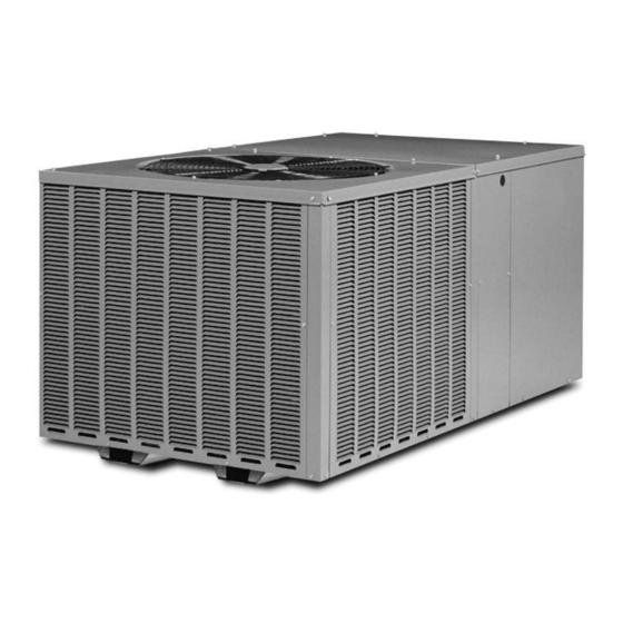
PACKAGE HEAT PUMPS FEATURING EARTH-
FRIENDLY R-410A REFRIGERANT
MPH 13 SEER SERIES – (2 - 5 TONS)
!
!
THESE INSTRUCTIONS ARE INTENDED AS AN AID TO
QUALIFIED, LICENSED SERVICE PERSONNEL FOR PROPER
INSTALLATION, ADJUSTMENT AND OPERATION OF THIS
UNIT. READ THESE INSTRUCTIONS THOROUGHLY BEFORE
ATTEMPTING INSTALLATION OR OPERATION. FAILURE TO
FOLLOW THESE INSTRUCTIONS MAY RESULT IN IMPROPER
INSTALLATION, ADJUSTMENT, SERVICE OR MAINTENANCE
POSSIBLY RESULTING IN FIRE, ELECTRICAL SHOCK,
PROPERTY DAMAGE, PERSONAL INJURY OR DEATH.
[ ] INDICATES METRIC CONVERSION
r e f r i g e r a n t
SUPERSEDES 92-20522-60-01
92-20522-60-02
Advertisement
Table of Contents

Related Manuals for Rheem MPH 13 SEER Series


Summary of Contents for Rheem MPH 13 SEER Series
- Page 1 PACKAGE HEAT PUMPS FEATURING EARTH- FRIENDLY R-410A REFRIGERANT r e f r i g e r a n t MPH 13 SEER SERIES – (2 - 5 TONS) THESE INSTRUCTIONS ARE INTENDED AS AN AID TO QUALIFIED, LICENSED SERVICE PERSONNEL FOR PROPER INSTALLATION, ADJUSTMENT AND OPERATION OF THIS UNIT.
-
Page 2: Table Of Contents
TABLE OF CONTENTS I. Safety Information ....................3 II. Introduction......................4 III. Checking Product Received ..................7 IV. Equipment Protection ....................7 V. Installation ......................7 A. General ......................7 1. Pre-Installation Check Points ................7 2. Location......................7 B. Outside Slab Installation ...................8 C. Clearances ......................8 D. Rooftop Installation ...................9 VI. -
Page 3: Safety Information
I. SAFETY INFORMATION WARNING THESE INSTRUCTIONS ARE INTENDED AS AN AID TO QUALIFIED, LICENSED SERVICE PERSONNEL FOR PROPER INSTALLATION, ADJUSTMENT AND OPERATION OF THIS UNIT. READ THESE INSTRUCTIONS THOROUGHLY BEFORE ATTEMPTING INSTALLATION OR OPERATION. FAILURE TO FOLLOW THESE INSTRUCTIONS MAY RESULT IN IMPROPER INSTALLATION, ADJUST- MENT, SERIVICE OR MAINTENANCE POSSIBLY RESULTING IN FIRE, ELECTRI- CAL SHOCK, PROPERTY DAMAGE, PERSONAL INJURY OR DEATH. -
Page 4: Introduction
II. INTRODUCTION This booklet contains the installation and operating instructions for your package heat pump. There are a few precautions that should be taken to derive maximum satisfaction from it. Improper installation can result in unsatisfactory operation or dangerous conditions. Read this booklet and any instructions packaged with separate equipment required to make up the system prior to installation. - Page 5 FRONT VIEW FIGURE 1 UNIT DIMENSIONS AND ACCESS LOCATIONS [1498.6 mm] CONDENSATE DRAIN ACCESS Model Height “A” 024, 030, 036 29 1/8" 042, 048, 060 37 1/8" CONTROL BOX ACCESS [77.7 mm] [1358.9 mm] [266.7 mm] [266.7 mm] BOTTOM VIEW ELECTRICAL CONNECTIONS RECOMMENDED UNIT DISCONNECT LOCATION...
- Page 6 DUCT CONNECTIONS ROUND DUCT CONNECTIONS [355.6 mm] [355.6 mm] SQUARE DUCT CONNECTIONS " 14.00" 14.00" " [355.6 mm] [19.05 mm] [355.6 mm] [19.05 mm] 14.00" 14.00" [355.6 mm] [355.6 mm] IMPORTANT: DO NOT SCREW OR DRILL OUTSIDE THE DESIGNATED AREAS.
-
Page 7: Checking Product Received
III. CHECKING PRODUCT RECEIVED Upon receiving the unit, inspect it for any damage from shipment. Claims for damage, either shipping or concealed, should be filed immediately with the shipping company. Check the unit model number, heating size, electrical characteristics, and accessories to determine if they are correct. -
Page 8: Outside Slab Installation
FIGURE 2 FIGURE 3 PACKAGED HEAT PUMP PACKAGED HEAT PUMP OUTSIDE SLAB INSTALLATION, BASEMENT OR PITCHED ROOFTOP INSTALLATION, ATTIC CRAWL SPACE DISTRIBUTION SYSTEM OR DROP CEILING DISTRIBUTING SYSTEM. MUST BE MOUNTED LEVEL. B. OUTSIDE SLAB INSTALLATION (Typical outdoor slab installations are shown in Figure 2.) 1. -
Page 9: Rooftop Installation
3. Unit is design certified for application on combustible flooring with 0" minimum clearance. 4. See Figure 2 for illustration of minimum installation-service clearances. D. ROOFTOP INSTALLATION 1. Before locating the unit on the roof, make sure that the strength of the roof and beams is adequate at that point to support the weight involved. -
Page 10: Condensate Drain, Outdoor Coil
IX. CONDENSATE DRAIN, OUTDOOR COIL The outdoor coil during heating operation will sweat or run water off. The outdoor coil will also run water off during the defrost cycle. See Section V, Installation, for mounting pre- cautions. FIGURE 4 REMOVABLE CONDENSATE DRAIN PAN AND REMOVAL PROCEDURE A small side panel grants... -
Page 11: Control Wiring
contactor L1 and L3 connections. Connect ground lead to ground lug on heater kit fuse block. b. Dual-circuit wiring: Remove unit power pigtails from heater kit fuse block and discard. Connect one set of high voltage field power circuit leads to the heater kit fuse block and connect ground lead to ground lug on heater kit fuse block. -
Page 12: Thermostat
F. THERMOSTAT Mount the thermostat on an inside wall about five feet above the floor in a location where it will not be affected by unconditioned air, sun, or drafts from open doors or other sources. READ installation instructions in heat pump thermostat package CAREFULLY because each has some different wiring requirements. -
Page 13: Operation
7. Is compressor running correctly. 8. Turn thermostat system switch to “HEAT.” Unit should stop. Wait 5 minutes, then raise temperature setting to above room temperature. Unit should run in heating mode and after about 30 to 50 seconds auxiliary heaters, if installed, should come 9. -
Page 14: Demand Defrost Control
continuously by setting the thermostat fan switch at the “ON” position. The revers- ing valve coil is de-energized when the changeover relay is energized. 2. In the heating mode, the first heat stage of the thermostat will energize one or more supplementary resistance heaters. -
Page 15: General Data
XVII. GENERAL DATA - MPH NOMINAL SIZES 2-5 TONS [7-17.6 kW] Model MPH - Series G24A-1K-00 G30A-1K-00 G36A-1K-00 G42A-1K-00 Continued -> Cooling Performance Gross Cooling Capacity Btu [kW] 24,600 [7.21] 29,800 [8.73] 36,600 [10.72] 43,500 [12.75] EER, SEER 11/13 11.15/13 11/13 11/13 Nominal CFM/ARI Rated CFM [L/s]... - Page 16 GENERAL DATA - MPH NOMINAL SIZES 2-5 TONS [7-17.6 kW] Model MPH - Series G48A-1K-00 G60A-1K-00 Cooling Performance Gross Cooling Capacity Btu [kW] 49,500 [14.5] 62,000 [18.17] EER, SEER 11/13 11/13 Nominal CFM/ARI Rated CFM [L/s] 1600/1550 [755/731] 2000/1900 [944/897] ARI Net Cooling Capacity Btu [kW] 47,500 [13.92] 59,000 [17.29]...
-
Page 17: Miscellaneous
XVIII. MISCELLANEOUS ELECTRICAL AND PHYSICAL DATA ELECTRICAL DATA – MPH SERIES G24A-1K-00 G30A-1K-00 G36A-1K-00 G42A-1K-00 G48A-1K-00 G60A-1K-00 Unit Operating 187-253 187-253 187-253 187-253 187-253 187-253 Voltage Range Minimum Circuit 20/20 21/21 25/25 33/33 33/33 41/41 Ampacity Minimum Overcurrent 25/25 25/25 30/30 40/40 40/40... -
Page 18: Airflow Performance
INDOOR AIRFLOW PERFORMANCE FOR 2-5 TON PACKAGE HEAT PUMPS – 230V MPH SERIES... - Page 19 INDOOR AIRFLOW PERFORMANCE FOR 2-5 TON PACKAGE HEAT PUMPS – 208V MPH SERIES...
-
Page 20: Electric Heater Kit
ELECTRIC HEATER KIT – 1 PHASE... -
Page 21: Wiring Diagram
FIGURE 7 WIRING DIAGRAM – MPH SERIES... -
Page 22: Charge Charts
FIGURE 8 CHARGING CHART 2.0 TON HP (R410A) 5 50 SYSTEM CHARGE CHART (COOLING) 5 00 4 50 4 00 3 50 3 00 2 50 2 00 SUCTION PRESSURE - PSIG SYSTEM CHARGE CHART (HEATING) SUCTION PRESSURE - PSIG 92-102273-01-01... - Page 23 FIGURE 9 CHARGING CHART 2.5 TON HP (R410A) SYSTEM CHARGE CHART (COOLING) SUCTION PRESSURE - PSIG SYSTEM CHARGE CHART (HEATING) SUCTION PRESSURE - PSIG 92-102273-02-01...
- Page 24 FIGURE 10 CHARGING CHART 3.0 TON HP (R410A) SYSTEM CHARGE CHART (COOLING) SUCTION PRESSURE - PSIG SYSTEM CHARGE CHART (HEATING) SUCTION PRESSURE - PSIG 92-102273-03-01...
- Page 25 FIGURE 11 CHARGING CHART 3.5 TON HP (R410A) SYSTEM CHARGE CHART (COOLING) SUCTION PRESSURE - PSIG SYSTEM CHARGE CHART (HEATING) SUCTION PRESSURE - PSIG 92-102273-04-01...
- Page 26 FIGURE 12 CHARGING CHART 4.0 TON HP (R410A) SYSTEM CHARGE CHART (COOLING) SUCTION PRESSURE - PSIG SYSTEM CHARGE CHART (HEATING) 100 120 140 160 180 200 220 SUCTION PRESSURE - PSIG 92-102273-05-01...
- Page 27 FIGURE 13 CHARGING CHART 5.0 TON HP (R410A) 5 5 5 5 0 0 SYSTEM CHARGE CHART (COOLING) 5 5 0 0 0 0 4 4 5 5 0 0 4 4 0 0 0 0 3 3 5 5 0 0 3 3 0 0 0 0 2 2 5 5 0 0 2 2 0 0 0 0...
- Page 28 CM 1008...