Table of Contents
Advertisement
Quick Links
Installation Instructions
Low Ambient Kit
Commercial Air Conditioners
Only qualified personnel should install and service the equipment. The installation, starting up, and servicing of
heating, ventilating, and air-conditioning equipment can be hazardous and requires specific knowledge and training.
Improperly installed, adjusted or altered equipment by an unqualified person could result in death or serious injury.
When working on the equipment, observe all precautions in the literature and on the tags, stickers, and labels that are
attached to the equipment.
September 2023
SAFETY WARNING
ACC-SVN137C-EN
Advertisement
Table of Contents

Related Manuals for Trane Kit-3938


Summary of Contents for Trane Kit-3938
- Page 1 Installation Instructions Low Ambient Kit Commercial Air Conditioners SAFETY WARNING Only qualified personnel should install and service the equipment. The installation, starting up, and servicing of heating, ventilating, and air-conditioning equipment can be hazardous and requires specific knowledge and training. Improperly installed, adjusted or altered equipment by an unqualified person could result in death or serious injury.
- Page 2 When working with or around hazardous chemicals, these compounds have the same potential impact to the ALWAYS refer to the appropriate SDS and OSHA/GHS environment. Trane advocates the responsible handling of all (Global Harmonized System of Classification and refrigerants. Labeling of Chemicals) guidelines for information on...
- Page 3 Copyright This document and the information in it are the property of Trane, and may not be used or reproduced in whole or in part without written permission. Trane reserves the right to revise this publication at any time, and to make changes to its content without obligation to notify any person of such revision or change.
-
Page 4: Table Of Contents
Table of Contents Overview ....... . 5 Kit Inspection ......5 Actuator Specifications . -
Page 5: Overview
Note: One copy of this document ships inside each kit and is is no damage prior to starting the installation. Contact the customer property. It must be retained by the unit’s Trane Parts Center if there is damage or missing components. maintenance personnel. Actuator Specifications This manual is divided into four sections. - Page 6 Overview Table 1. Unit conversion kits (continued) Parts List Refrigerant Number Rated Voltage Circuit Used With Unit Unit Tonnage Description Electronic Damper Actuator Actuator Cover w/ Top 1/2" X 9" Damper Shaft Actuator Template Sensor All Voltages Kit-3942 Circuit #2 CAUJ, RAUJ C40 - D121 Sensor Clip...
-
Page 7: Installation
Installation Units with Low Ambient Dampers The following procedures are broken down into five parts: • Damper actuator installation - single and dual circuit units Low Ambient Damper Actuator • Actuator control panel installation - kit dependent The direct coupled damper actuator utilizes a single-point •... - Page 8 Installation d. Drill the three holes using a 3/16-inch bit. Do not install c. Set the cover aside and drill the holes using a 3/16-inch the anti-rotation bracket. drill bit. Do not install the cover until the final checkout is completed. 8.
-
Page 9: Mounting The Actuator Control Panel
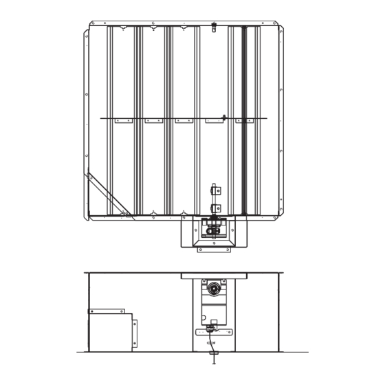
Installation Figure 2. Actuator cover assembly Figure 3. Actuator cover assembly Figure 4. Actuator mounting Mounting the Actuator Control Panel WARNING Only one control panel is required for single or dual circuit units. Hazardous Voltage! Refer to Table 1, p. 5 to determine if a control panel is required. -
Page 10: Condensing Temperature Sensor Installation
Installation Note: On units that require the mounting bracket, use the Figure 6. Actuator control panel locations for 40 mounting bracket as a template. through 130 ton units 2. Use the control panel mounting feet as a template for drilling the mounting holes. a. -
Page 11: Low Ambient Damper Wiring
Installation Table 2. Condenser coil sensor location (continued) Unit Size Unit Type Sensor Location - Ckt #1 "A” Sensor Location - Ckt #2 "B" RAUJ, CAUJ 32-1/8 "32-1/8" RAUJ, CAUJ 48-1/8 "48-1/8" RAUJ, CAUJ 28-1/8 "28-1/8" Low Ambient Damper Wiring Field wiring for the line voltage to the control panel should be 14 gauge minimum. -
Page 12: Connecting The Condenser Sensor Wires
Installation a. On units utilizing the number 2 actuator, the 24 VAC wires are connected to the same terminals as actuator WARNING number 1, i.e. Brn to 2TB34-8 and Blk to 2TB34-3. Proper Field Wiring and Grounding Figure 9. Actuator control cable hookup Required! Failure to follow code could result in death or serious injury. -
Page 13: Actuator Setup
Installation Figure 11. Low ambient connections diagram for all units Actuator Setup Figure 12. Damper actuator and blade alignment NOTICE Actuator Damage! Do not depress actuator clutch while actuator is energized as it could result in actuator damage. The actuator should be in the full clockwise (closed) position. To align the actuator hub in the correct fully closed position, refer to Figure 12... -
Page 14: Actuator Checkout
Installation Actuator Checkout signal will go to 0.0 VDC and the damper will drive to the closed position. The controller has a factory default setpoint of 105° F. This 5. Turn the main power Off and remove all jumpers and setpoint can be adjusted by installing a field supplied 1/4 watt reconnect all sensor leads. - Page 15 Notes ACC-SVN137C-EN...
- Page 16 For more information, please visit trane.com or tranetechnologies.com. Trane has a policy of continuous product and product data improvement and reserves the right to change design and specifications without notice. We are committed to using environmentally conscious print practices.