Advertisement
Quick Links
Advertisement

Related Manuals for Nautilus LEVERAGE SHOULDER NP-L4002


Summary of Contents for Nautilus LEVERAGE SHOULDER NP-L4002
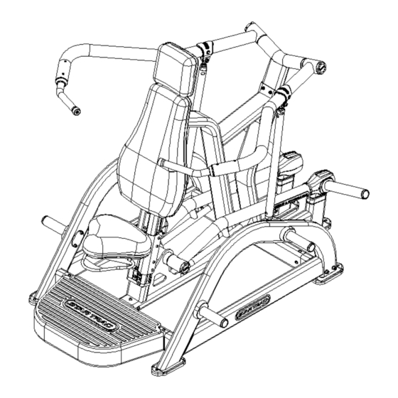
- Page 1 NP-L4002 SHOULDER PRESS OWNER’S MANUAL and INSTALLATION INSTRUCTIONS...
- Page 2 Leverage Shoulder Press Press Owner’s Manual Copyright 2016. Core Health and Fitness, LLC. All rights reserved, including those to reproduce this book or parts thereof in any form without first obtaining written permission from Core Health and Fitness, LLC. Every effort has been made to keep this information current; however, periodically, changes are made to the information herein, and these changes will be incorporated into new editions of this publication.
-
Page 3: Table Of Contents
TABLE OF CONTENTS • SAFETY INSTRUCTIONS / WARNINGS • WARNING LABLES WITH PART NUMBERS • EXERCISE GUIDELINES • MAINTENANCE AND SERVICE • INSTALLATION INSTRUCTIONS • HARDWARE Page 3... -
Page 4: Safety Instructions / Warnings
Proper Usage Do not use any equipment in any way other than designed or intended by the manufacturer. It is imperative that Nautilus equipment be used properly to avoid injury. Keep hands and feet clear at all times from moving parts to avoid injury. - Page 5 Ensure that any person(s) making adjustments or performing maintenance or repair of any kind is qualified to do so. Nautilus will provide service and maintenance training at our corporate facility upon request or in the field if proper arrangements are made.
- Page 6 19. Routinely inspect all fasteners that join attachments and framework tighten as needed to maintain the integrity of the unit. 20. Perform regular maintenance checks on the NAUTILUS equipment. Also, pay close attention to all areas most susceptible to wear.
-
Page 7: Warning Lables With Part Numbers
Warning labels and communication stickers The following pages show examples of the Nautilus® Leverage Strength® warning labels and communication stickers placed on the equipment as part of the manufacturing process. It is critical that owners maintain the integrity and placement of these stickers. If you find any stickers missing or damaged each sample indicated includes its corresponding part number so that replacements may be ordered. -
Page 8: Exercise Guidelines
Also, be certain that all the stickers (safety, instructional and/or other) are read and understood by each user. • All users should be instructed on the proper use of NAUTILUS as well as those actions that should be avoided. •... -
Page 9: Maintenance And Service
MAINTENANCE AND SERVICE LEVERAGE requires very little upkeep to keep your equipment performing at its best, the following guidelines are suggested. GENERAL CLEANING Wipe LEVERAGE with a light all-purpose cleaner, such as diluted Simple Green at a 30:1 solution. ... -
Page 10: Installation Instructions
Nyloc nut is used.) • All NAUTILUS Strength equipment MUST be secured to the floor using either 10mm or 3/8in. (grade 5 minimum) bolts. • This Installation Instructions Manual must be used in conjunction with the equipment’s Owner’s Manual. The Owner’s manual describes equipment setup and instructs members on how to use it correctly and safely. - Page 11 STEP #1 - UNPACK AND ASSEMBLE MAIN FRAME: 1. Remove and unwrap all product from shipping boxes. Lay all parts out in a clean open area to prepare for assembly. 2. Locate the FOOT PAD,SEAT PAD, MAIN FRAME, REAR FRAME and BACKING PLATE as shown below. 3.
- Page 12 STEP #2 - ASSEMBLE SIDE FRAMES: 1. Locate the SIDE FRAME LEFT, AND SIDE FRAME RIGHT as shown below. 2. As shown slide SIDE FRAME LEFT into STEP #1 ASSEMBLY. At each tube joint loosely Install three (M8 X 25MM, BUTTON HEAD BOLTS), and three (M8, FLAT WASHERS) do not tighten at this time.
- Page 13 STEP #3 - ASSEMBLE WEIGHT ARMS ASSY : 1. Locate one of the Leverage arms and slide it onto the corresponding shaft as shown below. The side of the Leverage arms that has the bearing and seal pre-installed will slide onto the shaft first. 2.
- Page 14 STEP #4: INSTALL ROM AJUST 1. Locate one of the Leverage ROM ADJUST to install. On the end with the spherical rod, insert two misalignment bushings and two O-rings, one bushing and one O-ring on each side of the rod end as shown below. 2.
- Page 15 STEP #5: INSTALL WEIGHT STORAGE 1. Install the WEIGHT HORN weldment and BACKING PLATE using two (M8 X 75MM, SOCKET HEAD BOLTS) four (M8,FLAT WASHERS) and two (M8, NYLOCK NUTS). Tighten to specified torque using a 6MM hex key and 13MM wrench.
- Page 16 STEP #6 – BEARING END CAPS: 1. After you have ensured smooth quiet operation of the Leverage unit, locate the four black END CAPS and push them into the end of the Leverage arms as shown. NOTE: Ensure that you press the caps in straight and evenly when installing. Once installed pull out on the cap to ensure they are fully snapped into place.
-
Page 17: Hardware
HARDWARE 731-0570 - M8x16mm 731-0365 731-0390 - M8*25mm Page 17... - Page 18 1. Perform all steps MACHINE CLEARANCE AND SPACING For the safe operation of Leverage Strength® NAUTILUS recommends that a clearance of 24 inches (60.96cm) be maintained between and behind machines including moving arms and levers. To insure safe entry and exit to each unit a walkway of at least 36 inches (91.44cm) inches is recommended front of, or on the entry side of each machine.
- Page 19 Page 19...
- Page 20 MANUFACTURER 4400 NE 77 Avenue, Suite 300, Vancouver, WA 98662 USA Tel +1 (888) 678-2476 www.corehandf.com CUSTOMER SUPPORT Contact your local distributor, or Core Health & Fitness directly at: Tel +1-800-503-1221 www.support@corehandf.com Part Number: 620-8420, Rev A.