
Related Manuals for Emerson Control Techniques FM-4


Summary of Contents for Emerson Control Techniques FM-4
- Page 1 FM-4 Programming Module Reference Manual P/N 400509-01 Revision: A7 Date: March 26, 2009 © Control Techniques Drives, Inc. 2001-2009...
- Page 3 FM-4 Programming Module Reference Manual Information furnished by Control Techniques Americas LLC (Control Techniques) is believed to be accurate and reliable. However, no responsibility is assumed by Control Techniques for its use. Control Techniques reserves the right to change the design or operation of the equipment described herein and any associated motion products without notice.
- Page 4 The following are trademarks of Control Techniques and may not be reproduced in any fashion without written approval of Control Techniques: EMERSON Motion Control, EMERSON Motion Control PowerTools, AXIMA, “Motion Made Easy.” Control Techniques is a division of EMERSON Co.
-
Page 5: Customer Support
Customer Support Control Techniques Americas LLC 12005 Technology Drive Eden Prairie, Minnesota 55344-3620 U.S.A. Telephone: (952) 995-8000 or (800) 893-2321 It is Control Techniques’ goal to ensure your greatest possible satisfaction with the operation of our products. We are dedicated to providing fast, friendly, and accurate assistance. That is why we offer you so many ways to get the support you need. - Page 6 Customer Service (Sales) (952) 995-8000 or (800) 893-2321 Email: customer.service@emersonct.com Authorized Control Techniques distributors may place orders directly with our Customer Service department. Contact the Customer Service department at this number for the distributor nearest you. Document Conventions Manual conventions have been established to help you learn to use this manual quickly and easily. As much as possible, these conventions correspond to those found in other Microsoft®...
-
Page 7: Safety Instructions
Safety Instructions General Warning Failure to follow safe installation guidelines can cause death or serious injury. The voltages used in the product can cause severe electric shock and/or burns and could be lethal. Extreme care is necessary at all times when working with or adjacent to the product. -
Page 9: Safety Considerations
Safety Considerations Safety Precautions This product is intended for professional integration into a complete system. If you install the product incorrectly, it may present a safety hazard. The product and system may use high voltages and currents, carry a high level of stored electrical energy, or control mechanical equipment that can cause injury. - Page 10 Isolation of control circuits The installer must ensure that the external control circuits are isolated from human contact by at least one layer of insulation rated for use at the applied AC supply voltage. viii...
-
Page 11: Table Of Contents
Table of Contents Customer Support ................. . iii Document Conventions . - Page 12 Input Lines View ................. . 100 Output Lines View .
- Page 13 Error Messages ................. . .242 Online Status Indicators.
-
Page 15: Introduction
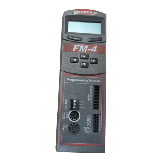
’on the fly’. The FM-4 module defines complex motion by a configuration file that includes setups, function assignments and programs. The configuration file is created using EMERSON Control Techniques PowerTools Pro software on a PC running Windows® 98, 2000, 2003, 2008, XP (SP2) (32-bit) or Vista (32-bit) operating system. Setup views have the same look and feel as dialog boxes. - Page 16 FM-4 Programming Module Reference Manual Fastening Latch 3 Row by 12 Character Display Soft Keys Direction Arrow Keys Programming Module 100-Pin Connector Inputs 485 + Expanded I/O 485 - SHLD (not used at this time) Sync. Input Outputs MODEL FM-4 PART 960498-01 Sync.
-
Page 17: Operational Overview
FM-4 Programming Module Reference Manual Operational Overview This section provides a complete functional description of the FM-4 module. It is intended to provide you, the user, with a thorough understanding of all operations. The description includes references to many FM-4 module and drive parameters which can be displayed and/or edited using PowerTools Pro software, or through any Modbus interface. -
Page 18: Keypad Interface
FM-4 Programming Module Reference Manual Keypad Interface The keypad and character display on the front of the FM-4 module provides navigation through a menu of common parameters and displays current functions. Navigation through the menu is accomplished with the six keys located below the display. - Page 19 Operational Overview Menu Screen EN-204 Adr01 MG-316 SECUR PROG* QUICK PBus- DVNET+ SECUR RAMPS JOG* HOME INDEX* Group Group Group Group Group Group Group Group Group Posn Fdbk <Prg.0.Init> Slave Address MacID Auto Log Out Stop <Jog.0.Vel> Home.0.Vel <Ind.0.Vel> GRAPH MENU MODIF MENU...
-
Page 20: How Motion Works
FM-4 Programming Module Reference Manual Numeric parameter units are sometimes shown before the actual value, because the parameter value and the units cannot be displayed on one line. The unit of measure will appear on the second line for about one second. Then the actual parameter value will appear. - Page 21 Operational Overview Gear Reducer External Home Sensor NT Motor with Encoder Carriage Sensor Point Home Offset Distance Figure 6: Basic Home Function, Example The figure above show a basic home function using a ball screw. This example uses most of the setup features in the PowerTools Pro Home view.
- Page 22 FM-4 Programming Module Reference Manual Figure 8: Marker Home Reference Position Sensor then Marker Selecting Sensor then Marker means the reference position is established using the first marker rising edge after the device sees the rising edge of the Home Sensor input function. Figure 9: Sensor then Marker Home Reference Position Example 1 Accuracy and Repeatability...
- Page 23 Operational Overview >800 µsec Sensor Marker Direction of Travel Figure 10: Sensor then Marker Home Reference Position Example 2 The Home Sensor must be “On” for at least 800 μsec to guarantee that it will be recognized. Sensor Min. On Time Sensor 800 μsec Figure 11:...
- Page 24 FM-4 Programming Module Reference Manual Figure 12: Calculated Home Offset, Peak Velocity Not Reached If the Home Reference is detected after the axis has reached its peak velocity, the axis will decelerate to the precise offset position. Calculated Home Offset Figure 13: Calculated Home Offset, Peak Velocity Reached Two examples below show operation when the specified offset is greater or lesser than the calculated offset.
- Page 25 Operational Overview Specified Offset Figure 15: Specified Home Offset, Backup Required End of Home Position The End of Home Position (End Posn) defines the home position in relation to the machine’s coordinate system. At the completion of the home, the value of the End of Home Position is put into the command position. Home Limit Distance This parameter places an upper limit on the incremental distance the motor will travel during the home.
- Page 26 FM-4 Programming Module Reference Manual The motor continues at that velocity until it first senses the Home Sensor input. It continues at the same velocity until the motor’s encoder marker channel is sensed. The rising edge of the motor’s encoder marker channel is used to establish the reference position.
-
Page 27: How Indexes Work
Operational Overview Figure 19: Home Sensor and Marker then Offset, Example When the device sees the rising edge of the Home Initiate function, it accelerates the motor to the Home Velocity. The motor continues at that velocity until it first senses the Home Sensor input. The motor continues on at the home velocity until the marker is activated. - Page 28 FM-4 Programming Module Reference Manual Figure 22: Indexes View Indexes use acceleration and deceleration ramps which may or may not reach the specified velocity depending on the total distance and the ramp values. For example, a short move with long acceleration and deceleration ramps may not reach the target velocity entered.
- Page 29 Operational Overview Absolute Index Absolute Index Start Position = 1 Rev Index Position = 5 Revs Figure 23: Absolute Index Example 1 In the example above, the current position is 1 rev. If this index is initiated, the motor will travel to a position of 5 revs no matter where it is sitting before the move.
- Page 30 FM-4 Programming Module Reference Manual Incremental Index Start Position = 1 Rev Index Distance = 2 Revs Figure 26: Incremental Index Example 2 Registration Index A Registration Index is used in applications where the motor must move until an object is detected and then move a specific distance from the point of detection, such as finding a registration mark and moving a distance beyond.
-
Page 31: How Communications Work
Operational Overview Rotary Minus indexes move to the specified position, but are forced to travel in the negative (or minus) direction. Rotary Minus index positions must be within the rotary rollover range. Example 6: As in examples 2 and 4 above, the starting position is at 90° and 80° is the specified position. A Rotary Minus index would travel 10°... - Page 32 FM-4 Programming Module Reference Manual was found, an EN-204 drive with a FM-4DN module. The Upload Drive Configuration dialog box contains the following information for every device found: • Ip Address/COM • Modbus Address ID • Drive Type • Module Type •...
- Page 33 Operational Overview • Drive Serial Number Figure 28: Download to Device ID 1 Dialog box Select the device to download to and click OK. Change Path Connection This function allows the user to change the drive and Ip address/Com port used for download and upload. It is used when the user has already selected one Ip address.Com port and wishes to change to another.
- Page 34 FM-4 Programming Module Reference Manual Figure 29: Change Path Dialog Box Select the device in the list and then click OK. The communication connection path will then be displayed in the status bar at the bottom of PowerTools Pro window. NVM Options for Uploading and Downloading Uploading When uploading from a FM-4 module, the values that were last downloaded are uploaded and put into a PowerTools Pro...
- Page 35 Operational Overview Update – This option will upload the current NVM parameter values from the FM-4 module and enter them into the user configuration (PowerTools Pro file). Once the NVM values have been stored in the file, the file is fully downloaded. Keep –...
- Page 36 FM-4 Programming Module Reference Manual If the user modifies parameters, and disconnects, the update button will be disabled, and the changes will not be sent. Options/Preferences/Ptools Operation Communications Tab This tab allows the user to set-up the serial communication baud rate. The drive baud rate and PowerTools Pro baud rate must match, default drive baud rate = 19200.
- Page 37 Operational Overview Figure 32: Preferences-PopUps Tab Download Section: Ignore saving file on Ptools/Drive revision conversion. On a download PowerTools Pro checks the firmware revision of the module that it is about to be downloaded to and is required to make changes to files that are to be downloaded to older firmware revisions. This check box allows the user to avoid saving the newer file before converting it to a previous revision.
- Page 38 FM-4 Programming Module Reference Manual Upload Section: Always convert Application to latest Ptool capability. When this option is selected, PowerTools Pro will automatically update an uploaded file to match the current functionality of PowerTools Pro. Always leave Application matching Module capability. When this option is selected, PowerTools Pro will default to upload and display the configuration to match the firmware revision and capabilities of the module.
-
Page 39: Secure Downloading
Operational Overview Standard Motor DDF Name The name of the standard motor ddf file is entered in the text box, the information in this file will be used to setup the configuration file, the default is stdmotor.ddf. User Motor DDF Name When a custom motor is created this is the name of the motor ddf file where the information is stored, default is motor.ddf. -
Page 40: Brake Operation
FM-4 Programming Module Reference Manual A dialog box will then open asking the user to select the secure file that they wish to download. Select the secure file that was just saved, then click Open. This will download the secure file to the target device. A secure file (.fm4s) cannot be opened or modified. -
Page 41: How Data Capture Works
Operational Overview How Data Capture Works Data Capture is a mechanism to capture data and display that data graphically. The capture mechanism is part of the drive and captures drive data as fast as 100 usec. Data is captured in a circular 8 K byte buffer. The format is fixed at 4 channels of 32 bit words for a total of 512 time samples. - Page 42 FM-4 Programming Module Reference Manual...
-
Page 43: Setting Up Parameters
FM-4 Programming Module Reference Manual Setting Up Parameters Status View Status Online Tab The Status Online tab (see Figure 33) is active when online and consists of the Motor Position group, Motor Velocity group, Control Loop group, Master Feedback group, and the Torque group. Figure 33: Status View - Online Status Tab - FM-4E Motor Position Group... - Page 44 FM-4 Programming Module Reference Manual Velocity Feedback The Velocity Feedback (VelFeedback) is the feedback (or actual) velocity. It is calculated using the change in position of the motor encoder. It will always return the actual motor velocity - even in synchronized applications in which the master axis is halted during a move.
-
Page 45: Information Tab
Setting Up Parameters Information Tab PowerTools Pro is designed to work with all releases of drive firmware. PowerTools Pro internally uses interface revisions to negotiate and define the application to match the connected drive. The first line shows the file name and user application for reference. Drive Information Group Firmware Part Number Displays the part number of the drive firmware. -
Page 46: Graph View
FM-4 Programming Module Reference Manual Graph View Figure 34: Graph View Data Capture Group Graph State There are three graph state conditions in the following order: Filling Buffer, Filled. Waiting for Trigger, and Filled and Triggered. The Run button commands the drive to begin a high speed data capture of the parameters as selected in each of the four data channels. - Page 47 Setting Up Parameters Timing Group The sliders can be moved in several different ways. 1. With the mouse pointer over the slider, left click and hold while dragging the slider back or forth to the desire setting. 2. With the mouse pointer over the slider, left click on the slider and then the arrow keys on the PC keyboard can be used to move the slider in fine increments.
-
Page 48: Setup View
FM-4 Programming Module Reference Manual Setup View The Setup View contains all of the primary system setup parameters. These parameters must be setup prior to using your system. By selecting Setup in the Hierarchy Tree, the Setup view will appear on the right side of the view (see Figure 35). The Setup view is divided into six groups, with an explanation of each function. - Page 49 Setting Up Parameters Gateway (FM-4E Only) This 32-bit parameter indicates the default Gateway address for the FM-4E. When attempting to communicate with a device on a different Subnet, the message must go through this gateway to reach it’s destination. For a detailed description of the Gateway address refer to the Industrial Ethernet Overview section in the FM-3 and FM-4 Connectivity Modules Reference Manual (P/N 400508-04).
-
Page 50: Motor View
FM-4 Programming Module Reference Manual handled. Messages are Modbus data, DeviceNet data, Keypad/Display information, and are only processed if a message is waiting. If no device is querying data from the FM-4 or sending data to the FM-4, then messages do not take up any time. Once messages have been processed, the remainder of the interrupt is dedicated to running the motion programs of user programs. - Page 51 Setting Up Parameters Selecting the wrong motor type can cause instability and may cause property damage to the motor and/or drive. Use Motor Data From .ddf File Check box When selecting a motor for use with the drive and FM-4 module, the user has two basic options: Use a motor that already exists in the standard motor definition file (StdMotor.ddf) or custom motor definition file (Motor.ddf).
- Page 52 FM-4 Programming Module Reference Manual Rotor Inertia This parameter specifies the inertia of the mo tor rotor. The drive uses this parameter to interpret the “Inertia Ratio” parameter. “Inertia Ratio” is specified as a ratio of reflected load inertia to motor inertia. Motor KE Specifies the Ke of the motor.
- Page 53 Setting Up Parameters Encoder Reference Motion Specifies the direction of motion assumed in phase plots of the encoder’s quadrature and summation signals. The supported values are CW(1) and CCW(0). Your encoder may have the same phase plot but is generated from a different direction of rotation.
- Page 54 FM-4 Programming Module Reference Manual Figure 37: Auto-Tune Dialog Box - Auto-Tune Mode 3 After the Auto-Tune Mode has been selected, click Proceed, to start the Auto-Tune. As the Auto-Tune is executing the gray check boxes will show the progress of the Auto-Tune. When the Auto-Tune is completed the Auto-Tune dialog box closes and the auto-tune results will be in the Values from Drive column on the Motor view.
- Page 55 Setting Up Parameters Move #3, Vel = 0.15 Electrical Cycles/sec (approx 1 rev/min), Distance < 1.0 Revolutions of motor, Direction = CW The parameters measured by Auto-Tune Mode 2 are those tested in Auto-Tune Mode 1 plus Phase Resistance and Phase Inductance.
- Page 56 FM-4 Programming Module Reference Manual Save .ddf Values Button Once the user has entered the data for the motor they are using, they may or may not wish to save the motor data to the Motor.ddf file so it can be easily recalled at a later time. If the user does not save the motor data to the Motor.ddf file, then the motor data will only reside in the specific application configuration file that it has been entered into.
-
Page 57: User Units View
Setting Up Parameters attempts to overwrite a standard motor. In this case, the user would need to change the motor name before saving to the .ddf file. Load and use motor parameters from matching motor in .ddf file If this option is selected, the motor data in the Motor.ddf or stdmotor.ddf file for the matching Motor Name will overwrite the data in the Motor Parameters column. - Page 58 FM-4 Programming Module Reference Manual Figure 39: User Units View Distance Group Units Name This is a 10-character name for the distance user units the user wants to use in the application. Decimal Places The number of decimal places set in this parameter determines the number of digits after the decimal point used in all distance and position parameters throughout the configuration.
- Page 59 Setting Up Parameters = 1.5 x 3.14... = 4.712 inches / revolution Characteristic Distance = 4.712 Scaling -------------------------------------------------------------------------- - Characteristic Length = 1 If the user decides to put a 5:1 reducer on the system, the user simply needs to change the Characteristic Length. Now the belt travels 4.71"...
-
Page 60: Master Units View
FM-4 Programming Module Reference Manual Decimal Places The number of decimal places set in this parameter determines the number of digits after the decimal point used in all real- time velocity parameters throughout the software. Using a high number of decimal places will improve velocity resolution, but will also limit the maximum velocity. - Page 61 Setting Up Parameters Encoder Setup Group Master Source Master Source (MasterAxis.Source) indicates the source of the master encoder input. FM-4E Only, select Custom Variable, the Module Variable text box will became available to enter a parameter. The custom variable can be entered two ways: by just typing the parameter into the text box using the program format for the variable, or click the Popup Variables button and the Select Variables from Tree window will open.
- Page 62 FM-4 Programming Module Reference Manual Units Name This is a text string up to 12 characters that will be used to define the units of distance traveled by the master axis for incoming synchronization signals. Decimal Places The number of decimal places set in this parameter determines the number of digits after the decimal point used in all distance and position parameters used in synchronized motion throughout the software.
-
Page 63: Virtual Master View - Fm-4E Only
Setting Up Parameters The gray box in the table above denotes the default setting for the master filter parameters. Enable Check Box The Enable check box is used to turn on or turn off the Master Position Filter. If selected, the filter is turned on (active) and the user must select the number of samples used by the filter. -
Page 64: Position View
FM-4 Programming Module Reference Manual Acceleration Acceleration (VirtualMaster.Accel) is the acceleration rate, in user units, that the virtual master will use to accelerate. This parameter is used when in either jog or indexing mode. Deceleration Deceleration (VirtualMaster.Decel) is the deceleration rate, in user units, that the virtual master will use to decelerate in either jog or index mode. - Page 65 Setting Up Parameters Figure 42: Position View - FM-4E Settings Group Define Home Position This is the value to which the position command will be set when the Define Home destination is activated. This is used in applications which do not use a home routine, but require a known reference point. The units are defined on the User Units View.
- Page 66 FM-4 Programming Module Reference Manual the drive will generate a Following Error Fault (F). All accumulated Following Error will be cleared when the drive is disabled. The Following Error Limit is defined in user units. Enable Software Travel Limits Check Box Select this check box to enable (or disable if clear) the software travel limits.
-
Page 67: Velocity View
Setting Up Parameters Position Feedback This is the feedback position of the motor in user units. Following Error The Following Error is the difference (in user units) between the Position Command and the Position Feedback. It is positive when the Position Command is greater than the Position Feedback. Encoder Position The motor position in encoder counts since power up when the value was set to zero. -
Page 68: Ramps View
FM-4 Programming Module Reference Manual = 0.5 Seconds A user wishes to accelerate from 100% programmed velocity to 175% in 0.5 Seconds. Therefore, the value they need to enter for Feedrate Decel/Accel is calculated as follows: FeedRate Decel/Accel = Decel Time/ % Change in FeedRate = (0.5 Sec) / (175% - 100%) =0.5 Sec / 75% = (0.5 Sec) / (100% * 75%) - Page 69 Setting Up Parameters smoothing at the beginning and end of the ramp but have constant (linear) acceleration rates in the middle of their profiles. The “5/8 S-Curve” is less smooth than the “S-Curve” but smoother than the “1/4 S-Curve”. S-Curve accelerations are very useful on machines where product slip is a problem. They are also useful when smooth machine operation is critical.
- Page 70 FM-4 Programming Module Reference Manual = Index 0 = Index 1 1250 Compound Index Blended Index Compound Index Blended Index User Ramps User Ramps Auto Ramps Auto Ramps Index.1.Accel specified by user is used to decelerate from Index.0.Vel, to Index.1.Vel, but overshoots since ramp is not aggressive enough to reach Index.1.Vel within Index.1.Dist of 3 Revs.
- Page 71 Setting Up Parameters Distance Velocity Accel Decel (Revs) (RPM) (RPM/sec) (RPM/sec) Index 0 1000 1000 Index 1 1250 2000 2000 = Index 0 = Index 1 1250 Compound Index Blended Index Compound Index Blended Index User Ramps User Ramps Auto Ramps Auto Ramps Index.0.Accel specified by user is used to accelerate up to Index.0.Vel.
-
Page 72: Torque View
FM-4 Programming Module Reference Manual example, if the motor is running at 50 revs/second and feedhold is activated with 2 seconds specified in the FeedholdDecelTime parameter, then the motor will actually slow and stop in 2 seconds as measured time (on a time/velocity profile) goes from 100% to 0%. -
Page 73: Distance Recovery View - Fm-4E Only
Setting Up Parameters Distance Recovery View - FM-4E Only When initiating gear or cam using the Master Axis to provide synchronization, distance is lost as we must follow the acceleration limitations. This distance can be recovered when at velocity by adding a distance recovery index on top of the gear operation or cam. - Page 74 FM-4 Programming Module Reference Manual Figure 49: Tuning View Load Group Inertia Ratio Inertia Ratio specifies the load to motor inertia ratio and has a range of 0.0 to 50.0. If the exact inertia is unknown, a conservative approximate value should be used. If you enter an inertia value higher than the actual inertia, the resultant motor response will tend to be more oscillatory.
-
Page 75: Faults View
Setting Up Parameters than the actual friction, it may result in velocity error or instability. If the Friction parameter is less than the actual friction, velocity error will be reduced but not eliminated. Position Error Integral Group Time Constant Check Box When this check box is selected it enables the Time Constant parameter. - Page 76 FM-4 Programming Module Reference Manual Figure 51: Faults Window When online, the Active Faults window, Reset button and Power Up group window become active. There will also be three tabs that appear, Fault Log, Fault Counts, and Drive Fault Log. Figure 52: Faults View Online - Faults Log Tab Active Faults Group...
- Page 77 Setting Up Parameters Fault Log Tab The Fault Log tab is visible when online and consists of a list of the ten most recent faults detected by the drive or module. These are saved in non-volatile memory to be preserved during power down. Faults are listed in reverse order of occurrence-the most recent fault is listed first, and older faults are pushed off the list.
-
Page 78: Setup Nvm View
FM-4 Programming Module Reference Manual A few faults are saved in non-volatile memory so that the total number of times they have occurred can be easily viewed. These faults tend to have hardware significance. Fault Code This is the faults parameter name. Fault Counts This is the number of times that the fault has occurred. -
Page 79: Devices / Vars Group
Setting Up Parameters Figure 55: Setup NVM View NVM Warning: Assigning parameters to NVM could shorten the life of your FM-4 or FM-4! The Non-Volatile memory list displays the parameters that will be saved so they can be restored after a powerdown. A command to store these parameters into the NVM is given to the module whenever a parameter on the list changes value (via a program or a communications network). - Page 80 FM-4 Programming Module Reference Manual Figure 56: PLS View A PLS can be used to turn on or off a bit based on feedback position, commanded position, or master feedback position. Eight global PLS’s are available for a single application. To operate a PLS, first it must be enabled (see the PLS enable destinations in the assignments view) and then the Absolute Position Valid source must be active.
-
Page 81: Capture View
Setting Up Parameters Off Point PLS.#.Status will be active when the selected source position is between the PLS.#.OnPosn and the PLS.#.OffPosn. Assume that the PLS.#.Direction is set to "Both". When traveling in the positive direction and the feedback position reaches the OnPosn, the PLS.#.Status will activate. - Page 82 FM-4 Programming Module Reference Manual the following parameters are captured and stored: Time, Command Position, Feedback Position, and Master Feedback Position. Figure 57: Capture View The user must determine which signals are used to enable, activate, and then reset the Capture component. A CaptureTriggered destination is then available to indicate to the user that data has been captured and is available for use.
- Page 83 Setting Up Parameters CaptureActivate If the Capture component is enabled and has been reset (CaptureTriggered is inactive), then the rising edge of CaptureActivate will capture the four data parameters and cause CaptureTriggered to be activated. If the Capture component is not enabled, or has not been reset, the CaptureActivate will be ignored. CaptureReset The CaptureReset is used to reset or re-arm the capture component after it has been activated.
- Page 84 FM-4 Programming Module Reference Manual The captured data remains in these parameters until the capture component is reset and CaptureActivate is activated. When the capture component is reset and CaptureActivate is activated, the data related to the previous capture will be over-written by the most recent capture data.
- Page 85 Setting Up Parameters Destinations that use captured data: Index/Jog Initiates – When one of the sources listed above is assigned to an Index or Jog Initiate, the captured information is automatically applied to the index starting point. This offers extremely high accuracy for initiation of motion, which is beneficial especially in synchronized applications.
- Page 86 FM-4 Programming Module Reference Manual Queue Object Exit Data[ ] Empty Clear Size Offset Full Level Compare Full Comparitor Select Enable Name Overflow Data In Data Out Queue Data = X Y = Queue Data Figure 61: Queue Object and Components Diagram A detailed explanation of each of the queue components is as follows: Queue Data The queue data is loaded into the queue by statements in the user program.
- Page 87 Setting Up Parameters Queue Sources and Destinations Sources Queue Exit This source activates when the Comparitor Select parameter is greater to or equal to the sum of the data entered into the queue, and the queue offset. Queue Empty This source is active if no data is stored in the queue. It will become inactive when the first piece of data is loaded into the queue and remain inactive until all data has been removed from the queue.
-
Page 88: Timers View - Fm-4E Only
FM-4 Programming Module Reference Manual QueueEmpty IF (# of Queue Objects = 0) QueueClear Set # of Queue Objects = 0 QueueFull IF (# of Queue and clear data in queue Objects = or > Full Level) Data In Source Select: Full MasterPosn Level... - Page 89 Setting Up Parameters Figure 63: Timers View - FM-4E Only Number of Timers This parameter determines the number of Timer objects that are available in the configuration. Use the spin control to change the number of Timers from 1 to 8. The Timers are numbered with a base number of 0. This means that if there are 5 Timers available, they will be numbered 0 through 4.
- Page 90 FM-4 Programming Module Reference Manual In the case of the Edge type timer, once the rising-edge occurs on the Input, it doesn't matter what happens to the state of the Input after that. The Output will always turn ON when the Preset Time is reached (unless the Reset activates before the Preset Time is reached).
- Page 91 Setting Up Parameters Note that if the Input is already ON when the Reset activates, the Output will not automatically activate at that point. The timer controller must see a rising edge on the Input to activate the Output. Figure 66: Edge Off Timer - Timing Diagram Level OFF Timer With this type of timer, when the Input of the timer activates, the Output turns ON automatically.
- Page 92 FM-4 Programming Module Reference Manual being ON reaches the Preset time, the Output turns ON. Figure 6 below shows an example timing diagram of the Cumulative On Timer. Figure 68: Cumulative ON Timer, No Reset - Timing Diagram Additionally, a Reset signal can be used to clear the cumulative timer and restart it at zero. The figure below shows an example of this.
- Page 93 Setting Up Parameters the Output of the timer turns OFF. If the Input turns ON again before the Preset time is reached, the clock resets to zero and waits again for the Input to turn OFF before resuming the count again. Figure 70: Cumulative OFF Timer - Timing Diagram Additionally, a Reset signal can be used to clear the cumulative timer and restart it at zero.
- Page 94 FM-4 Programming Module Reference Manual reaches Preset time, the Output turns ON. The Output will remain ON until the Timer Reset is activated. If a rising edge is seen on the Input while the Output is ON, it will be ignored and the Elapsed Time will NOT be reset. Figure 72: Watchdog Timer - Timing Diagram One Shot...
- Page 95 Setting Up Parameters However, if you wanted to hold that same output active for ten revolutions of the Master Encoder instead of ten seconds, you set the Timebase to Synchronized. This means that you are using the master encoder position to control the duration of the Timer rather than actual Time.
- Page 96 FM-4 Programming Module Reference Manual When the TimerEnable is deactivated, all output events associated with that Timer object will also deactivate and Elapsed Time will be set to zero. All timer types use the Enable even though it is not shown in the individual timing diagrams. See examples of how TimerEnable affects timer functionality in Figure 77 and Figure 78.
-
Page 97: Variables View
Setting Up Parameters Timer.#.TimerOutput The Timer Output state is controlled by the Timer Input, the Timer Type, and the other configuration settings of the Timer object. See the various timing diagrams in Figures 2 through 10 to see how Timer Output functions. The Timer Output can be assigned to multiple Destinations on the Assignments view just as any other Output Event. - Page 98 FM-4 Programming Module Reference Manual Figure 77: Variables View The following parameters are part of the Variables definition: Name This is a twelve-character string that allows the user to assign a descriptive name to the parameter. Spaces are not allowed in the name of a user variable.
-
Page 99: Bits View
Setting Up Parameters Bits View Bits act just like Variables except that they allow the user to store bit level parameters rather than 32-bit parameters. The user may customize each Bit by giving it a Name and an Initial Value. The Name for each bit may be up to 12 characters in length, and must start in an alpha character (non-numeric character). - Page 100 FM-4 Programming Module Reference Manual 32-bit Bit Register and Bit Masking When using different communications protocols (i.e. DeviceNet, Profibus, Modbus), it is often desirable to access groups of Bits in a single parameter, rather than having to access them individually. In the FM-4 module it is possible to access 32 Bits in a single parameter.
- Page 101 Setting Up Parameters FM-3/4 Write Network Master Read Mask Value Written data is AND’ed with the Mask and then written into 32-bit Value. Read data is read directly from the 32-bit Value and bypasses the Mask. Figure 80: User Bits Read/Write Process Configuring the Bit Mask Register The Bit Mask is a 32-bit parameter that can be configured through Power Tools Pro, in the User Program, or over the communications network.
-
Page 102: Packed Bits - Fm-4E Only
FM-4 Programming Module Reference Manual Figure 81: Bits Mask View To configure the mask in a user program, the parameter named BitRegisiter.#.ValueMask is written to. The mask can be written to using Hexadecimal based values or decimal based values. To write a hexadecimal value to the parameter, the hex value must be preceded with the characters "0x". - Page 103 Setting Up Parameters a user program, Bit0 of the Control Word in the Figure 84 below would not automatically change to 1. Bit0 will only be 1 if the master device sets that bit when writing to the Control Word. ControlWord.0 Value Bit0...
- Page 104 FM-4 Programming Module Reference Manual Packed Bits Control Words View Control Words handle data being written to the user defined drive bit-level parameters. The user configures the Control Word(s) by dragging-and-dropping the desired bit-level parameters they wish to write into the Control Word mapping. Figure 86 below shows the Packed Bits Control Words view onto which the user has dragged several motion initiate parameters.
- Page 105 Setting Up Parameters To delete parameters from the Control Word, simply drag and drop the parameter off the control word (see explanation above), or highlight the desired parameter to delete, and click the Delete button on the right side of the view. Note Parameters can be mapped while online, but cannot be sent to the drive using the Update to RAM function.
- Page 106 FM-4 Programming Module Reference Manual Using Pack Bits Control Words Once the Control Word(s) have been configured by the user, they can be utilized by fieldbus communications (i.e. Modbus, EtherNet I/P, Profibus, DeviceNet, etc.) or within a user program. Figure 88 shows an example in which the user will write to the Control Word 0 and 1 via Ethernet I/P.
- Page 107 Setting Up Parameters Word mapping. Figure 89 below shows the Packed Bits Status Words view onto which the user has dragged several status parameters. Figure 87: Pack Bits Status Words View Enable Packed Bits Control and Status Words In order to use the Pack Bits Control Word and Status Word mapping, the function must be enabled by activating the Enable Packed Bits Control and Status Words checkbox.
- Page 108 FM-4 Programming Module Reference Manual Online Status Tab (Available Online Only) While online with the device, the user can monitor the Status Word value (see Figure 90). The data is displayed in binary form for each individual bit of the Status Word(s), as well as hexidecimal and decimal format for each Status Word. Figure 88: Pack Bits Online Status Tab Using Pack Bits Status Words...
-
Page 109: I/O Setup Group
Setting Up Parameters I/O Setup Group The I/O Setup group contains views that control input and output functions as well as other drive functions. These views are as follows: Selector, Assignments, Input Lines, Output Lines, Analog Inputs, and Analog Outputs. These can be viewed by expanding I/O Setup then simply clicking on any one of the setup views underneath the I/O Setup. - Page 110 FM-4 Programming Module Reference Manual Inputs source group, you will see DriveInput.1 through ModuleInput.8, as shown in Figure 90. You can use these events to trigger certain actions (or destinations) on the right side of the view. To make an assignment in the FM-4 module occur, you must tie a source to a destination. Any source can be tied to any destination to create the desired system operation.
- Page 111 Setting Up Parameters Assignment Polarity The active state of an assignment can be programmed to be Active Off, Active On, or Custom using PowerTools Pro. Making an assignment “Active On” means that the destination will be active when the source it is assigned to becomes active, and is inactive when the source is inactive.
-
Page 112: Selector View
FM-4 Programming Module Reference Manual Index/Jog At Velocity – Activation of the command complete signal at the end of indexes and jogs will automatically capture data. A subsequent index, jog, or dwell can then use the captured data to start itself extremely accurately at the end of the previous motion. - Page 113 Setting Up Parameters Figure 93: Assignment View For example, if we entered 3 for the number of Selector Input Destinations, we would have 8 selection lines (Selector.Selection0 through Selector.Selection7). The Selector.Selection number that is activated is determined by the status of the Selector.Select lines when the Selector.Selector Initiate bit is activated.
-
Page 114: Input Lines View
FM-4 Programming Module Reference Manual Example 2: If Selector.Select2 is inactive, Selector.Select1 is active, and Selector.Select0 is active, then the total binary value would be as follows: = 0, S = 1, and S = 1. Therefore, Total Binary Value = (0 x 2 ) + (1 x 2 ) + (1 x 2 Total Binary Value = 0 + 2 + 1... -
Page 115: Output Lines View
Setting Up Parameters Figure 95: Input Line Diagram If the Input Line attached to the home sensor is debounced, the actual rising edge of the Home Sensor is used to determine the Home Reference Position (the debounce time ensures a minimum pulse width). Output Lines View The Output Lines View displays any functions that have been assigned to the drive or module hardware outputs. - Page 116 FM-4 Programming Module Reference Manual Figure 97: Analog Inputs View Enable Channel Check Box By default, the analog input channel is not enabled meaning that the drive is not reading the A/D value read by the analog circuit. If the check box is clear, the channel is not enabled and the configuration parameters for the analog input are unavailable and therefore have no effect.
-
Page 117: Analog Outputs View
Setting Up Parameters Bandwidth This parameter sets the low-pass filter cutoff frequency applied to the analog input. Signals exceeding this frequency will be filtered at a rate of 20 db per decade. Set Maximums Group Maximum Value This parameter is used for user unit scaling. Enter the maximum value in analog user units to which the maximum analog voltage should correspond. - Page 118 FM-4 Programming Module Reference Manual Figure 98: Analog Outputs View Enable Channel Check Box By default, the analog output channels are not enabled meaning that a value is not being sent to the analog circuit. When the channel is disabled (check box is clear), the configuration parameters for that analog output are unavailable and therefore have no effect.
-
Page 119: Jog View
Setting Up Parameters Minimum Value The analog output is a linear interpolation of the selected module variable between the minimum and maximum specified end points. Each end point is specified as the user value and the corresponding output value at that point. The number of decimal places for both values is taken from the selected module variable. - Page 120 FM-4 Programming Module Reference Manual Jog Name This is a descriptive character string which can be assigned to the specific jog. Giving a name to a jog can make the motion setup easier to follow. Time Base This list box allows the user to select between a jog that is based on time (Realtime) as defined by user units, normally in seconds, or a time based on Master position via an external encoder (Synchronized) set in the Master Units View.
- Page 121 Setting Up Parameters Jog.MinusActivate When this destination is activated, jogging motion will begin in the negative direction. The jog velocity is determined by which jog (Jog0 or Jog1) is active or not. A jog stops when this destination is deactivated. If the jog velocity is negative, Jog.MinusActivate will cause the motor to jog in the positive direction.
- Page 122 FM-4 Programming Module Reference Manual Figure 101: Jog Select Details If the Jog direction is reversed, the Jog.#.Decel value will be used to decelerate the motor to zero speed and then the Jog.#.Accel will be used to accelerate to the new (opposite sign) velocity. Note The Jog destinations cannot be initiated when any other motion type (homing, indexing, or programs) is in progress.
-
Page 123: Home View
Setting Up Parameters Home View The Home is used in applications in which the axis must be precisely aligned with some part of the machine. The Home is initiated with the Home.#.Initiate Destination or from a program. Figure 102: Home View Home Number The Home Number parameter displays which home sequence you are editing and allows you to scroll through multiple home sequences using the up and down arrows. - Page 124 FM-4 Programming Module Reference Manual If on sensor... Group These radio buttons determine how the system reacts if the Home.#.SensorTrigger is already active when the home is initiated. ’Back off before homing’ Radio Button If this radio button is selected, the drive will back off the sensor before beginning the home. It does this by moving the direction opposite to that specified by the sign of the home velocity.
- Page 125 Setting Up Parameters Below is a diagram of a home using the "Back off before homing" radio box, a Home Reference of "Sensor", and using a "Calculated Offset". Home Sensor Input Velocity Back off Sensor Move Time Start of Normal Home Routine Home Reference Position...
- Page 126 FM-4 Programming Module Reference Manual Home.#.LimitDistHit This source is activated when the home reference is not found before the Home Limit Distance is traveled. It will remain active until the home is initiated again. Destinations Home.#.Initiate The Home.#.Initiate destination is used to initiate the home function. The Home is initiated on the rising edge of this function. The device will not initiate a Home if there is an Index, Jog, or Program in progress, or if the Stop destination is active or if a travel limit is active.
-
Page 127: Index View
Setting Up Parameters Index View An index is a complete motion sequence that moves the motor a specific incremental distance or to an absolute position. The index is initiated with the Index.#.Initiate destination or from a program. Figure 104: Index View Index Number The Index Number parameter selects the index number with a scroll box. - Page 128 FM-4 Programming Module Reference Manual updated via fieldbus, by simply writing to the index position parameter. If the analog input's Destination is set to an Index number, the index's position value will be updated by the Analog to Position scaling found in the Analog Input view. A Registration Index runs at the specified velocity until a registration sensor is seen or until it reaches the Registration Limit Distance.
- Page 129 Setting Up Parameters Deceleration. When the Time check box is enabled, these parameters automatically become maximums for use in the calculations. Figure 105: Time Check Box Enabled If the values for Max.Velocity, Max.Acceleration, and Max.Deceleration are such that the distance cannot be covered in the specified time, the Index.ProfileLimited flag will activate when the index is initiated, indicating the index cannot be performed as desired.
- Page 130 FM-4 Programming Module Reference Manual Max Velocity Max Decel Max Accel Trapezoidal Move Index.ProfileLimited activates for this profile Triangle Move Time Figure 106: Timed Index Profiles Enable Index PLS This check box enables (when checked) or disables the Index PLS function. An Index PLS is similar to a global PLS (explained in the PLS View section), but is incremental in nature.
- Page 131 Setting Up Parameters ’Analog’ or ’Sensor’ Radio Buttons Select one of these radio buttons to determine what signal will be used as your registration trigger. If ’Sensor’ is selected, a source must be assigned to the Index.#.SensorTrigger. Typically a proximity sensor is wired to a hardware input, and therefore a module or drive input source is assigned to the Index.#.SensorTrigger, but any source can be used.
- Page 132 FM-4 Programming Module Reference Manual Index Sources and Destinations Sources Index.AnyCommandComplete Active when any index motion command is completed. If a stop is activated before the index has completed, this destination will not activate. Deactivated when any new index command is initiated. Index.#.Accelerating This source is active while an index is accel erating to its’...
- Page 133 Setting Up Parameters Index.#.Sensor Trigger If registration to Sensor is selected, when this destination activates, motor position is captured and is used as the registration point for registration type indexes. Adding and Deleting Indexes Adding or removing indexes from the user configuration can be done in three ways. Indexes may only be added or deleted while offline.
-
Page 134: Gearing View
FM-4 Programming Module Reference Manual Gearing View Figure 107: Gearing View - FM-4, FM-4DN, and FM-4PB Figure 108: Gearing View - FM-4E Use Scale Check Box - FM-4E Only Select this check box (Gear.UseScaleEnable) to enable the Scaling feature and disable Gear Ratio. Scaling allows the user to use irrational ratios such as 1.0/7.0 that were not possible with the single parameter ratio (Gear.Ratio). - Page 135 Setting Up Parameters Gear Ratio Gearing is used to fix the motion of the motor to the motion of the master axis signal at a specified ratio. This is commonly called “electronic line shafting” or “electronic gearing”. To gear the motor to the master axis, a ratio must be specified as a relationship between follower distance units and master distance units.
-
Page 136: Camming View - Fm-4E Only
FM-4 Programming Module Reference Manual Figure 109: Gearing Acceleration Ramp Description The GearRatio can be changed on the fly (while in motion), but acceleration or deceleration must be enabled to use ramps to achieve the new ratio. If gearing accel and/or decel ramps are not enabled, the motor will attempt to achieve the new ratio in one trajectory update (800<t<16000 microseconds). - Page 137 Setting Up Parameters MASTER FOLLOWER AXIS AXIS (SLAVE) Figure 110: Mechanical Master and Slave Follower As the master axis (the cam lobe) rotates, the follower axis produces a non-linear motion profile. This same profile can then be produced with a single motor driving a linear axis programmed with an electronic cam. The cam motion object uses a master/follower principal in a synchronized mode and also has a follower with Realtime mode that allows the follower to travel through its cam table without a physical master axis moving.
- Page 138 FM-4 Programming Module Reference Manual Cam Number Use the arrows of the spin box to increment or decrement the Cam Number and view the setup information for that Cam number. A maximum of 32 different cam tables can be created. Name The user can specify a cam name (Cam.#.Name) of up to 12 alphanumeric characters.
-
Page 139: Torque Mode View - Fm-4E Only
Setting Up Parameters Cam Table Plot Error Figure 112: Cam Table View With a Smilely Face When the Master and Follower parameter values are entered into the cam table the graph is updated to reflect these values. If PowerTools is unable to plot the graph due to these values a smilely face will appear in the graph area of the view. To correct this error just change parameter values until the smilely face is cleared and the plot appears. - Page 140 FM-4 Programming Module Reference Manual The Velocity Limiting has values and enables for acceleration and deceleration. This allows for position control integration with compound and blended Indexes. We recommend using the graphical monitor to debug your motion integration. Figure 113: Torque Mode - Online Torque Mode Settings Group Torque Command...
-
Page 141: Multiple Profiles
Setting Up Parameters Deceleration Check Box Select this check box (TorrqueMode.DecelEnable) when an deceleration ramp is desired. Deceleration This parameter (TorqueMode.Decel) is the deceleration ramp for the velocity limit feature, when enabled. Multiple Profiles Motor motion or "Axis" motion may be generated from either of two Profiles: Profile.0 and Profile.1. Each of these Profiles can run any type of motion (i.e. - Page 142 FM-4 Programming Module Reference Manual The Profile view allows the user to view the Position Command and Velocity Command for each profile individually. An example of this view is shown below. Figure 114: Profile View - Online The following example program code runs Index 0 on Profile 0, Wait for 1 second, and then initiate Index 1 on Profile 1. The diagram shows how the two profiles look individually, and then shows how the motion looks after being summed by the two profiles.
-
Page 143: Stopping Motion
Setting Up Parameters Stopping Motion MotionStop from a Program The MotionStop command will cause all motion to stop regardless of what type of motion it is, or where it was initiated from. Upon activation of the MotionStop, all motion will begin to decelerate to a stop using the standard Stop deceleration ramp. That ramp is defined using the StopDecel parameter. -
Page 144: Network Group
FM-4 Programming Module Reference Manual Index.AnyCommandComplete instruction if the Profile.MotionStop is used. To avoid this condition, “OR Profile.1.Stop” has been inserted after the Wait For Index.AnyCommandComplete. Example: 1 Program 0 – Running on Task 0 Gear.Initiate On Profile.0 Do While TRUE Wait For DriveInput.1 = ON Index.1.Initiate On Profile.1 Wait For (Index.AnyCommandComplete OR Profile.1.MotionStop) - Page 145 Setting Up Parameters Figure 115: Modbus View An external device such as a Human Machine Interface (HMI) or PLC can be used to monitor or edit individual drive parameters. The Epsilon EP-P drive uses a 32-bit Modbus RTU communications protocol. In order to view or modify a parameter, a Modbus address must be assigned to the specific parameter.
- Page 146 FM-4 Programming Module Reference Manual Any individual Modbus address can be deleted by selecting the parameter you wish to delete, and click on the Remove button. The address selected will be removed from the list. If you wish to delete all of the Modbus addresses that have been created, then simply click on the Remove All button.
- Page 147 Setting Up Parameters Figure 118: Modbus Master View - Slave Tab Master Slave ∆a ∆b ∆c ∆d Figure 119: Modbus RTU Timing Diagram Δa - Response Gap - Specifies the maximum timeout for the response packet. If a response packet is not detected within this period then the slave device status is set to no_response.
- Page 148 FM-4 Programming Module Reference Manual Δd - Message Gap - Specifies idle period between the last packet received and the next packet transmitted. This gap allows for extended quite time for multiple slaves on the same communications path; where slaves may be actively monitoring Modbus packets and may miss the standard Inter Frame gap.
-
Page 149: Modbus View
Setting Up Parameters Modbus View The Modbus View or Modbus RTU/TCP View is used to assign Modbus addresses to individual parameters. By selecting Modbus or Modbus RTU/TCP in the Hierarchy Tree, the Modbus or Modbus RTU/TCP View will appear on the right. - Page 150 FM-4 Programming Module Reference Manual Figure 121: Modbus View - FM-4E Only An external device such as a Human Machine Interface (HMI) or PLC can be used to monitor or edit individual module parameters. The FM-4 module and drives use a 32-bit Modbus RTU communications protocol. In order to view or modify a parameter, a Modbus address must be assigned to the specific parameter.
-
Page 151: Modbus Master View
Setting Up Parameters Any individual Modbus address can be deleted by selecting the parameter you wish to delete, and click on the Remove button. The address selected will be removed from the list. If you wish to delete all of the Modbus addresses that have been created, then simply click on the Remove All button. - Page 152 FM-4 Programming Module Reference Manual Figure 124: Modbus Master View - Slave Tab Master Slave ∆a ∆b ∆c ∆d Figure 125: Modbus RTU Timing Diagram Δa - Response Gap - Specifies the maximum timeout for the response packet. If a response packet is not detected within this period then the slave device status is set to no_response.
-
Page 153: Devicenet View - Fm-4Dn Only
Setting Up Parameters DeviceNet View - FM-4DN Only For those modules that have the DeviceNet option, please refer to the FM-3 and FM-4 Connectivity Reference Manual, P/N 400508-04, which can be found on the Control Techniques MME Power CD. Profibus View - FM-4PB Only For those modules that have the Profibus option, please refer to the FM-3 and FM-4 Connectivity Reference Manual, P/N 400508-04, which can be found on the Control Techniques MME Power CD. - Page 154 FM-4 Programming Module Reference Manual...
-
Page 155: Programming
FM-4 Programming Module Reference Manual Programming Programs Motion Programs are a series of indexes, homes and jogs that have been previously setup. You combine these with other programming steps to create a complex motion profile. Each motion program provides a series of movements in conjunction with other machine functions. - Page 156 FM-4 Programming Module Reference Manual This button will insert a bookmark on the line of code on which the cursor is placed. Bookmarks allow the user to mark certain sections of the program for easy access to at a later time. The next BookMark and Previous BookMark buttons can be used to jump from one bookmark to the next very quickly.
-
Page 157: Cyclic Program View
Programming Lock Program Toggling this button will lock and unlock the program for editing. When locked, the user is not able to modify the program code. After downloading, the program automatically locks to prevent the user from inadvertently changing program statements. - Page 158 FM-4 Programming Module Reference Manual Figure 126: Cyclic Programs View Program Name This is a 12 character string that the user can assign to an individual program. It allows the user to give a descriptive name to the program for ease of use. Update Rate This parameter defines the number of Update rates the cyclic program has to finish.
-
Page 159: User Program View
Programming User Program View Click on Programs\Program#, the program view will appear on the right (see Figure 121). The left side (pane) of this view contains the program instructions. The right side of the Programs view contains the Program Toolbar above the program code area. -
Page 160: Real Time Program View
FM-4 Programming Module Reference Manual Run Anytime Enable Check Box (Programs Only) Some applications require the ability to run a program as soon as a fault occurs or continue running a program even through a fault condition. In order to do this, a program must be classified as "Run Anytime". To define a program to be able to run during a fault or while the drive is disabled, the "Run Anytime"... -
Page 161: Program Multi-Tasking
Programming Program Multi-Tasking Many applications require the operation of a background task that operates outside of the main program loop, but must be consistently processed. For instance, a background task that performs calculations for values sent to an operator interface or a background task that monitors parameters for fault detection. - Page 162 FM-4 Programming Module Reference Manual been assigned by the user), the whole process starts over at the first task. This process is accurate as long as no program is blocked. The following figure shows examples of user programs and task numbers and how the drive processes them. Control Loop + User Program on one Task Control Loop User Program...
- Page 163 Programming Cyclic Program Utilization Control Loop + Cyclic Prog + User Prog on one Task. Cyclic set to 80% Program Utilization set to 80% means cyclic program is suspended after 80% of update is reached, then resumed next update Control Loop Cyclic Program User Program Update Rate...
- Page 164 FM-4 Programming Module Reference Manual Cyclic Program Utilization Same as above except Cyclic Program Utilization is set to 40%. In set to 40% this scenario, Cyclic Program cannot complete within 3 updates and so Overrun Error occurs in next update. Need less code in Cyclic Prog, higher Utilization setting, or Larger Cyclic Update Rate setting Overrun Error Control Loop...
- Page 165 Programming Control Loop + Cyclic Prog + User Progs on three Tasks. Note how Cyclic Program Utilization when the number of Tasks is the same as the Cyclic Program set to 70% Update Rate setting, some programs get shortchanged. This should be avoided by changing the Cyclic Program Update Rate Control Loop Cyclic Program...
- Page 166 FM-4 Programming Module Reference Manual User program can be "choked" if too much code is put into real time program Control Loop Control Loop Real Time Program User Program User Program Update Rate Figure 137: Diagram of User Program and a Real Time Program When the Real Time program is to large and can not be completed in the update rate time the drive will fault.
- Page 167 Programming The following three figures show how the drive processes Real Time, Cyclic, and User Programs with different number of tasks. Cyclic Program Utilization Control Loop + Real Time + Cyclic + User Program on one Task. set to 80% Cyclic Program Update Rate set to 4x Trajectory Update Rate and Utilization set to 80%.
-
Page 168: Program Instruction Types
FM-4 Programming Module Reference Manual Control Loop + Real Time + User Programs on three Tasks. Cyclic Program fUpdate Rate set to 4x Trajectory Update Rate and Utilization set to 80%. Control Loop Real Time Program Cyclic Program User Program Update Rate Cyclic Update = 4x Update Rate Figure 142:... - Page 169 Programming Case: When the Switch expression value and the case number instruction match, all the instructions that follow the case instruction up to a Break or EndSwitch are executed. This includes instructions following the next case instructions and the default instruction found.
- Page 170 FM-4 Programming Module Reference Manual in a program the program will halt. It is commonly used inside of If/Then/Endif constructs to end the program if a certain condition has been met. For example: If DriveInput.1=OFF Then Endif For example: If DriveInput.1=ON Then DriveOutput.1=ON Endif For Count/Next...
- Page 171 Programming Index.0.Accel = (Index.0.Accel*1000)+5.00 If/Then/Endif This is a program flow control instruction used to selectively run a section of code only if a logical test condition is true. If the test evaluates to true the code between the If/Then and Endif lines is executed. If the test evaluates to false the code is not executed and the program skips to the next line of code after the Endif.
- Page 172 FM-4 Programming Module Reference Manual Wait For Time This program instruction is used to halt program execution for a specified period of time. This instruction is not a motion instruction and can be used while a motion instruction is executing. Units: Seconds, Resolution: 0.001 seconds A comment is automatically inserted after the “Wait For Time”...
- Page 173 Programming See GoTo instruction for additional examples. GoTo The GoTo instruction is used in conjunction with the Label: instruction to cause program flow to transfer to a specified location within a program. The destination label is allowed to be above or below the GoTo instruction within the same program.
- Page 174 FM-4 Programming Module Reference Manual Example 2: Modulus(5,-1.4) Returns -0.6 Example 3: Modulus(-5,1.4) Returns 0.6 Example 4: Modulus(-5,-1.4) Returns -0.8 The exact mathematical function for the Modulus function is as follows: Modulus(x,y) = x - (FLOOR (x/y)) * y Where FLOOR is defined as rounding the argument down to the next whole integer value towards negative infinity. Example: FLOOR(-3.5715) = -4 The FLOOR function itself is not available to the user within a user program.
- Page 175 Programming Example: var.var0 = 0 indexinitiate var.var0 Var.var0 = 1 + var.var0 wait for index.anycommandcomplete goto a: CompoundIndexInitiate by Expression: This motion instruction is used to vary the index numbers making up a compound index. No comments will be added to this instruction as the index selected can change anytime before the initiate command is encountered.
- Page 176 FM-4 Programming Module Reference Manual Wait For Index.AnyCommandComplete Index.37.Initiate ‘Absolute,Posn=120.60mm,Vel=50.2mm/s Wait For InPosn Index.CompoundInitiate This program instruction is used to initiate an index which has no deceleration ramp. The index accelerates or decelerates towards the next index velocity using the next index acceleration ramp. The index will finish at velocity. The program then moves on to the next index.
- Page 177 Programming Complex Velocity Profile Drive Output 3 ON Drive Output 2 Drive Output 1 Index 0 Index 1 Index 2 Time Index.0.CompoundInitiate ‘Incremetal,Dist=5.000in,Vel=50in/s DriveOutput.1=ON ‘Turns ON immediately after Index.0 is started Index.1.CompoundInitiate ‘Incremental,Dist=20.000in,Vel=75in/s DriveOutput.2=ON ‘Turns ON immediately after Index.1 is started Index.2.Initiate ‘Incremental,Dist=10.000in,Vel=30in/s DriveOutput.3=ON...
-
Page 178: Adding And Deleting Programs
FM-4 Programming Module Reference Manual Examples: Jog.0.PlusInitiate ‘Vel=27.2in/s Jog.1.PlusInitiate ‘Sync,Vel=1.000in/in Jog.MinusInitiate This program instruction is used to initiate jogging in the negative direction. The Jog.Stop instruction is used to stop jogging motion. A comment is automatically inserted after the Jog.MinusInitiate instruction which shows key data about the particular jog. The comment starts with the apostrophe ‘... -
Page 179: Run Anytime Programs
Programming Delete Program button The Delete Program button (shown below) will delete a program from the user configuration. The highest numbered program will automatically be deleted unless a different program is selected on the Programs heading screen. To delete a specific program, click on the Programs branch in the Hierarchy Tree. -
Page 180: Example Programs
FM-4 Programming Module Reference Manual Figure 145: Program View (FM-4E) with “Run Anytime” Check Box Enabled When a fault occurs, the drive will still be disabled, and no motion will be possible. For this reason, it may be necessary to reset the fault in the “Run Anytime”... - Page 181 Programming Out and Return – More Complex Description: Home, Wait For an input, Move out to an absolute position, set an output, dwell for 1 second, clear the output, return to home position, repeat the out and return sequence until the stop input halts the program. Home.0.Initiate ‘Sensor,Offset=0.000in,Vel=-10.0in/s ModuleOutput.1=ON...
- Page 182 FM-4 Programming Module Reference Manual Simple Jogging within a Program Jog+ when DriveInput.2 goes ON and stop when it goes off. Jog- when DriveInput.3 goes ON and stop when it goes off. This could also be accomplished using the Jog input functions when there is no program running. Do While (TRUE) ‘Repeat until the program is halted If(DriveInput.2=ON) Then...
- Page 183 Programming Endif Wait For PLS.0.Status=ON ‘Start the Index when PLS.0 goes on ‘(every 100 inches). Index.1.Initiate ‘Incremental,Sync,Dist=20.0in,Vel=1.0in/in Index.0.Initiate ‘Absolute,Sync,Dist=0.0in,Vel=2.0in/in Wait For Index.AnyCommandComplete Loop Synchronized Jog with Manual Phase Adjustment The motor controls a lugged conveyor belt which is synchronized to another lugged conveyor belt. Jog.0 is configured as a “Synchronized”...
- Page 184 FM-4 Programming Module Reference Manual If((ModuleInput.3=OFF) AND (ModuleOutput.3=ON)) Then ModuleOutput.3=OFF Endif ‘Decrease the fill amount once every time ModuleInput.4 is pressed. If ((ModuleInput.4=ON) AND (ModuleOutput.4=OFF)) Then Index.1.Dist = Index.1.Dist - 0.10 ‘ounces ModuleOutput.4=ON ‘ModuleOutput.4 is used to make sure that the distance is ‘incremented only once each time ModuleInput.4 is pressed.
- Page 185 Programming ‘input is on Index.3.Dist = PosnCommand ‘Read the Position Command into Index.3’s ‘absolute position. Endif Wait For ModuleInput.1=OFF ‘Wait until the “Learn” input goes off Wait For ModuleInput.2=OFF ‘Wait until the “Skip” input goes off Subroutine for Jogging the Axis into the Desired Position (Program 1) ‘Allow jogging until either the “Learn”...
- Page 186 FM-4 Programming Module Reference Manual...
-
Page 187: Parameter Descriptions
FM-4 Programming Module Reference Manual Parameter Descriptions This section lists all programmable and feedback parameters available. The parameters are listed alphabetically by variable name (shown in italics below the on screen name) and give a description. Range is dynamic and depends on User Unit scaling. The units of the parameters are dynamic and depend on selected User Units. - Page 188 FM-4 Programming Module Reference Manual Bit Number Value Bit.B# This read/write bit may be used in a program as an intermediary variable bit controlled by the user. Bit.B# is one of 32 bits that make up the BitRegister parameter. Assigned to communication networks such as DeviceNet, Profibus and Modbus, Bit.B# may be used to transfer events that have occurred in a PLC to the FM-4/4 program.
- Page 189 Parameter Descriptions Commutation Angle Correction CommutationAngleCorrection The difference between the electrical angle as determined at power up from the U, V, and W commutation tracks and the electrical angle as determined from the marker pulse or UVW transitions. This value will be zero until the marker pulse is detected or UVW transition is detected.
- Page 190 FM-4 Programming Module Reference Manual Characteristic Distance DistUnits.CharacteristicDist This parameter is the distance the load travels (in user units) when the motor travels the characteristic length (in motor revolutions). This parameter is used along with the DistUnits.CharacteristicLength to establish the relationship between user distance and actual motor travel distance.
- Page 191 Parameter Descriptions Drive Input Force DriveInput.#.Force Input can be forced either On or Off. This parameter is the state to which the input will be forced when the ForceEnable bit is activated. Drive Input Force Enable DriveInput.#.ForceEnable If DriveInput.#.ForceEnable parameter is activated, then the state of the DriveInput.#.Force bit will override the current input state.
- Page 192 FM-4 Programming Module Reference Manual Drive Output Encoder Scaling Enable DriveOutputEncoder.ScalingEnable When on, this parameter enables the use of the drive encoder output scaling feature. Drive Serial Number DriveSerialNumber This displays the serial number of the Drive to which the FM-4 module is attached. Active Fault Fault.#.Active The specified fault is active.
- Page 193 Parameter Descriptions Faulted Fault.Faulted Any fault will activate this event. Module Faults Bitmap Fault.ModuleFaultsBitmap This parameter is a 32-bit register which holds all of the module fault status bits. Following is a list of all module faults and their associated bit numbers: 1 = Module invalid configuration fault 2 = Module NVM invalid fault 3 = Module power up self test fault...
- Page 194 FM-4 Programming Module Reference Manual Code FM-4 WatchdogTimer OverSpeed InvalidConfiguration PowerUpSelfTest RMSShuntPower MotorOverTemperature OverTemperature Auto-Tune WatchdogTimer InvalidConfiguration NVMInvalid PowerUpTest FollowingError TraveLimitPlus TraveLimitMinus ProgramFault NoProgram DevicenetConnTimeout DevicenetBusOffInt DevicenetDupMacId TrajectoryFault ProfibusParameterizationFlt ProfibusWatchdogFault ProfibusConfigurationFault Fault Log - Power Up Count FaultLog.#.PowerUpCount This is the module power up count at the time that the fault occurred. Fault Log - Power Up Time FaultLog.#.PowerUpTime This is the module power up time when the fault occurred.
- Page 195 Parameter Descriptions than the actual inertia, the result could be a significant overshoot during ramping. If the Inertia setting is smaller than the actual inertia, following error during ramping will be reduced but not eliminated. If the Friction is greater than the actual friction, it may result in velocity error or instability.
- Page 196 FM-4 Programming Module Reference Manual Enable Following Error FollowingErrorEnable This parameter can be setup from the Position view or from a program. When enabled, a following error fault will be generated if the absolute value of the Following Error exceeds the Following Error Limit. Following Error Limit FollowingErrorLimit This parameter is used when the FollowingErrorEnable bit is set.
- Page 197 Parameter Descriptions Gear Command In Progress Gear.CommandInProgrees This source will activate when Gearing is initiated either from a program or through an assignment. The source will remain active as long as gearing is in operation. This source can be active even if the motor is not in motion as long as gearing is active.
- Page 198 FM-4 Programming Module Reference Manual 1 = Filled - Waiting Trigger: Continue putting data into the buffer, check back into previous sampled data for the trigger condition 2 = Manually Triggered: User pressed the stop button, the buffer will have what ever data is available 3 = Filled and Triggered: Stop loading buffer, trigger is found and offset data after the trigger is in the buffer ready for upload Graph.TriggerState2...
- Page 199 Parameter Descriptions Deceleration Home.#.Decel The Deceleration ramp parameter is used during all the home moves specified in user units. Decelerating Home.#.Decelerating This source is active during any deceleration while the specified home is in progress. Decelerating will turn off and on based on the type of Home selected.
- Page 200 FM-4 Programming Module Reference Manual Home Reference Home.#.Reference This parameter determines how the reference position is determined. The parameter can have one of three different values: 'Sensor', 'Marker', 'Sensor then Marker'. When the home reference is 'Sensor' the rising edge of the 'Home Sensor' input function is used to establish the reference position.
- Page 201 Parameter Descriptions Acceleration Index.#.Accel This parameter is the average Acceleration rate used during the index. Units are specified on the User Units view in the PowerTools Pro software. Accelerating Index.#.Accelerating This source is active while an index is accelerating to its target velocity. Once the index reaches the target velocity, or begins to decelerate, the Index.#.Accelerating source will deactivate.
- Page 202 FM-4 Programming Module Reference Manual Distance Index.#.Dist This parameter is the Incremental distance that the index will travel or the absolute position for the specified index in user units. If an index type of Registration is selected, then this is a limit distance, or the maximum distance the index will travel if a registration sensor is not seen.
- Page 203 Parameter Descriptions PLS Status Index.#.PLSStatus Controlled by the PLSOn and PLSOff Points, this is relative to the distance commanded since the start of the index. Index.#.PLSStatus will be active if the distance traveled from the start of the index is greater than the Index.#.PLSOnDist and less than the Index.#.PLSOffDist.
- Page 204 FM-4 Programming Module Reference Manual Velocity Index.#.Vel This parameter sets the target velocity of the specific index. The units for this parameter are specified in the User Units Setup view. When an index is initiated, it will ramp up to this velocity at the specified acceleration rate and run at speed until it decelerates to a stop (assuming the index is not compounded).
- Page 205 Parameter Descriptions Select Jog.Select0 This destination is used to select between the jogs. It is used along with the Jog.PlusActivate and Jog.MinusActivate destinations. If the Jog.Select0 destination is not active then the Jog.0 setup parameters will be used for jogging. If the Jog.Select0 input function is active, the Jog.1 setup parameters will be used for jogging.
- Page 206 FM-4 Programming Module Reference Manual Initiate Minus Jog.#.MinusInitiate This is used inside a program to initiate a specific jog. When this bit is active, jogging motion will be initiated in the negative direction at the specified jog velocity. Initiate Plus Jog.#.PlusInitiate This is used inside a program to initiate a specific jog.
- Page 207 Parameter Descriptions Module Input Debounce Time ModuleInput.#.DebounceTime The Module Input Debounce Time parameter is the minimum time a digital input must be on in order to be recognized by the FM-4 module. This feature helps prevent false triggering in applications in electrically noisy environments. Module Input Force ModuleInput.#.Force Input can be forced either On or Off.
- Page 208 FM-4 Programming Module Reference Manual Module Output Force ModuleOutput.#.Force A module output can be forced either On or Off. If the ForceEnable bit is activated, the ModuleOutput.#.State will be set to this value. Module Output Enable Force ModuleOutput.#.ForceEnable If ModuleOutput.#.ForceEnable is activated, then the state of the ModuleOutput.#.Force bit will override the current output state.
- Page 209 Parameter Descriptions Packed Bits Status Word Value PackedBits.StatusWord.#.Value When accessing the Packed Bits Status Words for network mapping or use in a program, the Value parameter is what holds the data. When used in a program, the "P ackedBits." and the ".Value" portions of th e parameter name are optional. Therefore, to read the Status Word Value in a program, the following lines of code are all interchangeable: Var.MyVar = PackedBits.StatusWord.0.Value Var.MyVar = PackedBits.StatusWord.0...
- Page 210 FM-4 Programming Module Reference Manual destination has been activated. Master Posn Valid must be active (Master Define Home is activated) if using a master signal for PLS source. PLS Rollover Enable PLS.#.RotaryRolloverEnable This parameter is used to enable the RotaryRolloverPosn for the individual PLS. PLS Rollover Position PLS.#.RotaryRolloverPosn This parameter is the absolute position of the first repeat position for this PLS.
- Page 211 Parameter Descriptions Position Feedback PosnFeedback Feedback position is the actual motor position in user units. PosnCommand minus the PosnFeedback is the FollowingError Position Feedback In Counts PosnFeedbackInCounts Motor encoder position in encoder counts since power up. This position reflects the feedback position of the motor and is not scaled into user units.
- Page 212 FM-4 Programming Module Reference Manual Response Response The Response parameter adjusts the velocity loop bandwidth with a range of 1 to 500 Hz. In general, it affects how quickly the drive will respond to commands, load disturbances and velocity corrections. A good value to start with (the default) is 50 Rotary Rollover Enable RotaryRolloverEnable This parameter is used in applications with a predefined repeat length.
- Page 213 Parameter Descriptions Software Travel Limit Minus Activate SoftwareTravelLimitMinusActive The SoftwareTravelLimitMinusActive source is active when the SoftwareTravelLimitMinusPosn is reached or exceeded. Motion will come to a stop using the TravelLimitDecel ramp. Software travel limits are not active unless enabled and Absolute Position Valid is active. Software Travel Limit Plus Activate SoftwareTravelLimitMinusPosn The SoftwareTravelLimitMinusActive source will activate when the SoftwareTravelLimitMinusPosn is reached or exceeded.
- Page 214 FM-4 Programming Module Reference Manual Limited Torque Command TorqueCommandLimited This is the actual torque commanded to the motor. This value is the result after the TorqueCommand is limited by the current foldback or the TorqueLimit value (if enabled). Torque Level TorqueLevel This parameter is compared to the TorqueCommand.
- Page 215 Parameter Descriptions Travel Limit Minus Active TravelLimitMinusActive This source is active when the TravelLimitMinusActivate is active. Travel Limit Plus Activate TravelLimitPlusActivate This destination is used to activate the travel limit plus fault. It should be assigned to the travel limit plus sensor. When it is activated the drive will decelerate to a stop using the deceleration rate defined in the TravelLimitDecel parameter.
- Page 216 FM-4 Programming Module Reference Manual Velocity Command VelCommand The Velocity Command is the velocity that the FM-4 module is commanding the motor to run at. This command is generated by the drive velocity control loop. It is displayed in user units. Velocity Feedback VelFeedback This is the feedback (or actual) velocity.
- Page 217 Parameter Descriptions Scaling - FM-4E Only VirtualMaster.CharacteristicLength The numerator (top value of the scaling fraction) is the VirtualMaster.CharacteristicLength and is used with VirtualMaster.CharacteristicDistance to create the virtual master conversion ratio scaling. Converting the user units distance into virtual counts. Virtual MasterCharacteristicLength Scaling = VirtualMaster.CharacteristicDistance Deceleration - FM-4E Only...
- Page 218 FM-4 Programming Module Reference Manual...
-
Page 219: Installation
FM-4 Programming Module Reference Manual Installation Basic Installation Notes You are required to follow all safety precautions during start-up such as providing proper equipment grounding, correctly fused power and an effective Emergency Stop circuit which can immediately remove power in the case of a malfunction. See the “Safety Considerations”... -
Page 220: Electrical Installation
FM-4 Programming Module Reference Manual Gently pull the FM away from Press down on the the drive. A slight rocking latch located on motion may be used to loosen the top of the FM. the FM's connector. Grip the FM on each side of the LCD. - Page 221 Installation Function Module 2.8 k * A high speed diode (such as a 1N4000) is required for inductive loads such as a relay, solenoid or contactor. Load Load Load 10 - 30 Single Point PE Ground 2.8 k I/O Supply + 10 to 30 Vdc 10 to 30 OUTPUT...
-
Page 222: Software Installation
FM-4 Programming Module Reference Manual Software Installation PowerTools Pro software was designed for users who need access to all setup options and diagnostic information for the drive. The software provides access to all commonly used drive parameters. PC System Configuration Minimum Required: •... -
Page 223: Starting And Exiting Powertools
Installation Starting and Exiting PowerTools Starting the Software 1. Click the Start button on the taskbar at the bottom left of the screen. 2. Click on the Programs selection. The Programs menu appears. 3. Click on the “Control Techniques” folder icon. 4. - Page 224 FM-4 Programming Module Reference Manual • Choose a command from the Help menu. • Click the Help button on a dialog box or view. • Click the Help button on the toolbar. • Click the Context Sensitive Help button on the toolbar and then the field on the view.
-
Page 225: Quick Start
FM-4 Programming Module Reference Manual Quick Start The quick start guide provides information on the basic operation and functions of the FM-4 module. The quick start steps cover only the most basic steps required to setup a FM-4 module for use with a drive. Basic Setup Steps Step 1: Opening a New Configuration Window To open a new configuration window, click either on the New File button at the left end of the PowerTools Pro toolbar, or... - Page 226 FM-4 Programming Module Reference Manual Figure 151: Setup View On this view, you must enter the following parameters before entering other setup views: Drive Type – Select, from the list box, the type of drive to which the FM-4 module is attached. E Series Only Line Voltage –...
- Page 227 Quick Start Figure 152: User Units View Now set up the parameters in the Distance group on the User Units view. The Tab key is used to easily jump through the available parameters. After entering data in a field, press the Tab key to move to the next parameter. The parameters you must fill out are as follows: Units Name –...
- Page 228 FM-4 Programming Module Reference Manual Figure 153: Position View To set up Following Error Limit and Software Travel Limits, fill out the following parameters in the Limits Group: Enable Following Error – This check box enables (when selected) and disables the following error fault capability. If selected, a following error fault is generated whenever following error exceeds the value entered in the parameter text box.
- Page 229 Quick Start Figure 154: Ramps View Travel Limit Decel – The deceleration ramp is used if either a Software or Hardware Travel Limit is encountered. The deceleration units of the ramp are defined in the User Units view under the Acceleration group. Torque View If the application calls for specific torque levels and limits, use the parameters on this view.
- Page 230 FM-4 Programming Module Reference Manual Step 3: Making Assignments The Assignments view is found by expanding the I/O Setup group in the Hierarchy Tree. The Assignments define how the system operates. Sources, located on the left side of the view, are functions or events that activate based on drive/motor activity.
- Page 231 Quick Start Figure 157: Output Lines View A name can also be given to each hardware output line. Figure 157 shows how to enter a name for an individual output line. Name – This 12-character string allows a descriptive name assignment to an output line. This makes the configuration easier to follow.
- Page 232 FM-4 Programming Module Reference Manual Jog Deceleration - Is the average deceleration rate used when decelerating to zero speed or to the new target velocity. Home Setup Next, select the Home view from the Hierarchy Tree. Figure 159 shows the Home view and its associated home parameters. Home Reference –...
- Page 233 Quick Start Figure 160: Index Setup View (Absolute Type) Indexes use the following parameters: Index Name - Is a 12-character string that gives a descriptive name to an index. Index Type – Selects the desired type of index from the list box. An Absolute index means the load will travel to an exact position with respect to the home reference point.
- Page 234 FM-4 Programming Module Reference Manual Figure 161: Index Setup View (Incremental Type) Now that all of the motion parameters are setup, the jogs and indexes can be initiated through assignments to hardware inputs that were made on the Assignment view. Step 5: Creating a Program Now that the drive setup is complete, assignments are made, and motion profiles are defined, a program can be created.
- Page 235 Quick Start Drag Drop Figure 162: Program View The window in the middle of the view allows selection from a list of Program Flow and Motion instructions. To insert an instruction into the programming window, you can use the “drag-and-drop” method also used in making assignments. Simply position your mouse pointer over the instruction you wish to use, click the left mouse button and hold it down.
-
Page 236: Example Application Start Up
FM-4 Programming Module Reference Manual A comment is automatically inserted after the index instruction, which shows key data about the specific index. Notice comments start with the ‘ apostrophe character. A “Wait For Index.AnyCommandComplete” instruction is automatically inserted after each Index.Initiate. This ensures that the index has completed before the program continues on to the next line of code. - Page 237 Quick Start Position View The example wishes to limit the Following Error to 0.25 Inches or one motor revolution, and the Software Travel Limits of +20 and 0 Inches. To setup following error limit and software travel limits, fill out the following parameters in the Limits Group: Enable Following Error –...
- Page 238 FM-4 Programming Module Reference Manual Drag and Drop Method Figure 166: Assignments View The Input Lines view shows all of the assignments that have been made to the Inputs group of Sources. After all assignments for the example application have been made, the Input Lines view should look like Figure 167. Figure 167: Input Lines View Notice that a Name can be associated to each input line.
- Page 239 Quick Start Figure 168: Output Lines View Home Setup The example application calls for setup of the following parameters: Home Reference –The example calls for a Home to Sensor; therefore, “Sensor” is selected as the home reference. Because of this selection, the home profile will travel at its target velocity until the Home.0.SensorTrigger is activated. Figure 166, shows the Home.0.Sensor Trigger has been assigned to ModuleInput.2.
- Page 240 FM-4 Programming Module Reference Manual Absolute Index Figure 169: Index Setup View (Absolute Type) Indexes 0 and 1 are both Absolute type indexes and use the following parameters: Index Name - Is a 12-character string that gives a descriptive name to an index. Index Type –...
- Page 241 Quick Start Distance – The distance is a signed value that specifies the distance the load will travel from the start position. The sign of this parameter determines direction of travel for the load. The distance of Position C has been set to 2.5 inches. Velocity –...
- Page 242 FM-4 Programming Module Reference Manual Wait For – This program instruction halts program execution until the expression becomes True. Once True, the program continues with the next line of code. The example program uses a Wait For DriveInput.1 so that the program will wait until DriveInput.1 is activated, then continue on.
-
Page 243: Tuning Procedures
FM-4 Programming Module Reference Manual Tuning Procedures The drive uses closed loop controllers to control the position and velocity Travel Limit of the attached motor. These position and velocity controllers and the associated tuning parameters are in effect when the drive is in velocity or pulse mode and have no effect when the drive is in Torque mode. - Page 244 FM-4 Programming Module Reference Manual • Feedforwards = Disabled Tuning steps If your Inertia Ratio is greater than 10 times the motor inertia go directly to the Intermediate Level tuning. No Tuning No tuning will be required in most applications where the load inertia is 10 times the motor inertia or less. Basic Level Adjust Response to obtain the best performance.
-
Page 245: Tuning Parameters
Tuning Procedures Tuning Parameters Inertia Ratio Inertia Ratio specifies the load to motor inertia ratio and has a range of 0.0 to 50.0. A value of 1.0 specifies that load inertia equals the motor inertia (1:1 load to motor inertia). The drives can control up to a 10:1 inertia mismatch with the default Inertia Ratio value of 0.0. -
Page 246: Determining Tuning Parameter Values
FM-4 Programming Module Reference Manual Feedforwards Feedforward gains are essentially open loop gains that generate torque commands based on the commanded velocity, accel/ decel and the known load parameters (Inertia Ratio and Friction). Using the feedforw ards reduces velocity error during steady state and reduces overshoot during ramping. - Page 247 Tuning Procedures If your application has less than a 10:1 inertia mismatch, the default parameter settings will be acceptable. If the inertial mismatch is greater than 10:1, use the following table for initial parameter settings. Parameter Setting Friction 0.00 Inertia Ratio 1/3 to 1/2 Actual Response 500/Inertia Ratio...
- Page 248 FM-4 Programming Module Reference Manual The figure below shows the relationship of Torque Command to the Velocity Feedback. There is increased torque during the Accel ramp (Ta), constant torque (Tc) during the constant velocity portion of the ramp and decreased torque (Td) during the decel ramp.
- Page 249 Tuning Procedures For horizontal loads or counterbalanced vertical loads use the following formula: • Td)) − 2000 Where: IR = Inertia Ratio R = ramp in ms/kRPM Ta = (unsigned) percent continuous torque required during acceleration ramping (0 - 300) Td = (unsigned) percent continuous torque required during deceleration ramping (0 - 300) Vm = motor constant value from Table 18 below...
- Page 250 FM-4 Programming Module Reference Manual Percent Continuous/volt RPM /volt Scaled Velocity Motor Drive Scaled Torque Command Command Output (default)) Output (default)) NT-320 5.16 NT-330 6.87 NT-345 6.72 NT-355 EN-208 5.97 MG-316 3.17 MG-340 3.14 MG-455 2.44 NT-345 6.72 NT-355 5.97 MG-455 EN-214 2.44...
-
Page 251: Diagnostics And Troubleshooting
FM-4 Programming Module Reference Manual Diagnostics and Troubleshooting Diagnostic Display The diagnostic segment display on the front of the drive shows drive status, FM-4 module status, and fault codes. When a fault condition occurs, the drive will display the fault code, overriding the status code. The alphanumeric display on the FM- 4 module provides additional fault information. - Page 252 FM-4 Programming Module Reference Manual Fault Codes A number of diagnostic and fault detection circuits are incorporated to protect the drive. Some faults, such as High DC Bus and Motor Over Temperature can be reset with the Reset button on the front of the drive or the Reset input function. Other faults, such as Encoder Faults, can only be reset by cycling power “Off”...
- Page 253 Diagnostics and Troubleshooting Segment Display Fault Action to Reset Bridge Disabled FM-4 Keypad Display Max Following Error Reset Button or Input Line Flw Err Trav (-) Travel Limit +/- Auto Trav (+) Normally on for one All "On" second during power up Dependent on ** Fault ** FM-4...
- Page 254 FM-4 Programming Module Reference Manual Power Module This fault is generated when a power stage over-temperature, over-current or loss of power stage logic supply occurs. This can be the result of a motor short to ground, a short in the motor windings, a motor cable short or the failure of a switching transistor.
- Page 255 Diagnostics and Troubleshooting FM-4 Fault A 4 will be displayed on the diagnostic segment display on the drive when the FM-4 module experiences one of the following faults. DvTrjFlt This fault occurs when the drive has received trajectory data from the FM module that indicates a problem or drive following error is extremely large.
-
Page 256: Drive Faults
FM-4 Programming Module Reference Manual Drive Faults The Active Drive Faults dialog box is automatically displayed whenever a fault occurs. There are two options in this dialog box: Reset Faults and Ignore Faults. Resetting Faults Some drive faults are automatically reset when the fault condition is cleared. Others require drive power to be cycled or the drive to be “rebooted”... - Page 257 Diagnostics and Troubleshooting Programming Error Messages These Red Dot Error messages occur while you are working in the Program view. When creating a program, the parser is executed when you left mouse click, when you arrow off the current Line, when you enter the carriage return, when you paste or when you drop a drag source.
-
Page 258: Online Status Indicators
FM-4 Programming Module Reference Manual Problem/Message Cause Solution The destination variable only See message. accepts a Boolean or Event value The destination variable only See message. accepts quoted "text" The destination variable only See message. accepts selection text The destination variable's You attempted to assign a number with a greater The User Units setup will allow you to define the desired resolution is less than the resolution... - Page 259 Diagnostics and Troubleshooting To setup the Watch Window, select Tools\Watch Window from the PowerTools Pro menu. If not online with the module, Watch Window will be unavailable on the menu. Upon selecting Watch Window, the following window will appear. Figure 173: Watch Window The Select Drive Parameters window as seen in Figure 174 allows the user to specify which parameters are to be seen in the Watch Window.
- Page 260 FM-4 Programming Module Reference Manual Select Defaults The Select Defaults button adds the most commonly used parameters to the Watch Window. Select I/O The Select I/O button will add the Drive and Module digital inputs and outputs to the Watch Window. Close The Close button will close the Select Drive Parameters window, while the Watch Window will remain open.
-
Page 261: Diagnostic Analog Output Test Points
Diagnostics and Troubleshooting Diagnostic Analog Output Test Points The drive has two 10 bit Analog Outputs which may be used for diagnostics, monitoring or control purposed. These outputs are referred to as Channel 1 and Channel 2. They can be accessed form the command connector on the drive or from the diagnostic output pins located on the front of the drive. - Page 262 FM-4 Programming Module Reference Manual Black (GND) Yellow Blue 10 Ohm 10 Ohm DGNE Cable Command Connector (J5) DGNE Cable Figure 176: Diagnostic Cable (DGNE) Diagram...
-
Page 263: Specifications
FM-4 Programming Module Reference Manual Specifications Power consumption: 3 W from drive power supply. I/O Supply Voltage: 10 Vdc-30 Vdc. Function Electrical Characteristics ON State Voltage 10 Vdc-30 Vdc ON State Current 2 mA-6.5 mA Inputs OFF State Voltage 0 Vdc-3 Vdc OFF State Current 0 µA-400 µA Max. - Page 264 FM-4 Programming Module Reference Manual AX4-CEN CDRO...
-
Page 265: Cable Diagrams
Specifications Cable Diagrams EN Drive EN Drive w/ FM-3 w/ FM-3 SCSLD-x Encoder EN Drive EN Drive w/ FM-3 w/ FM-3 EN Drive EN Drive w/ FM-3... - Page 266 FM-4 Programming Module Reference Manual SNCE-XXX Cable Pin 1 RED/WHT YEL/WHT BLU/WHT BLK/WHT +5 Vdc +5 Vdc DRAIN WIRE SNCDD-001.5 Cable +5 Vdc Pin removed DRAIN WIRE Completely remove pin 4 CONNECTOR END VIEW CONNECTOR END VIEW...
- Page 267 Specifications SNCO-003 Cable Pin 1 Pin removed DRAIN WIRE SNCI-003 Cable .68 MAX. 2.00 MAX. Pin 1 +5 Vdc DRAIN WIRE...
- Page 268 FM-4 Programming Module Reference Manual SNCLI-003 Cable +5 Vdc DRAIN WIRE...
- Page 269 Specifications CMDX-XXX Cable Pin 1 Pin 1 Note: Inner foil shields are already mechanical connected to outer braid shield by raw cable manufacture. RED/BRN Input I/O 1 BRN/RED Input I/O 2 BLK/BLU Input I/O 3 BLU/BLK Input I/O 4 WHT/ORG RS-485+ Some early shipments of this cable have WHT/YEL ORG/WHT...
- Page 270 FM-4 Programming Module Reference Manual CMDO-XXX Cable Pin 1 Note: Inner foil shields are already mechanical connected to outer braid shield by raw cable manufacture. RED/BRN Input I/O 1 BRN/RED Input I/O 2 BLK/BLU Input I/O 3 BLU/BLK Input I/O 4 WHT/ORG RS-485+ Some early shipments of this cable have WHT/YEL...
- Page 271 Specifications CDRO-XXX Cable Pin 1 BLU/PUR Encoder Output A/ PUR/BLU Encoder Output A ORG/PUR Encoder Output B/ PUR/ORG Encoder Output B BRN/PUR Encoder Output Z/ PUR/BRN Encoder Output Z RED/BLU Encoder +5VDC Supply BLU/RED Encoder Supply Common GRN/BLK I/O Supply+ BLK/GRN Drive Enable Input WHT/BLU...
- Page 272 FM-4 Programming Module Reference Manual TIA-XXX Cable Pin 1 (Typ) .63" (Typ) 2 1/2" Pin 1 DDS-XXX Cable SHELL DRAIN DB-9 MALE WIRE BLACK WHITE 485+ BLUE 485- 485+ 485- DB-9 FEMALE DB-9 MALE...
- Page 273 Specifications TERM-H (Head) Terminator TERM-T (Tail) Terminator Note See the "Multi-drop Communications" section for resistor values.
- Page 274 FM-4 Programming Module Reference Manual CMDS-XXX Cable 1 1/2" MAX. 3 3/4" MAX. BRAID SHIELD FORM WIRE GRN/YEL PE/GND CMMS-XXX Cable 1 1/2" MAX. BRAID SHIELD FORM WIRE GRN/YEL PE/GND...
- Page 275 Specifications CFCS-XXX Cable 3 3/4" MAX. 1 1/2" MAX. Pin 1 WHT/BRN BRN/WHT WHT/GRY GRY/WHT RED/ORG ORG/RED RED/BLU +5 VDC +5 Vdc BLU/RED RED/GRN MOTOR OVERTEMP MOTOR OVERTEMP GRN/RED NOT USED NOT USED...
- Page 276 FM-4 Programming Module Reference Manual CFCO-XXX Cable Pin 1 WHT/BRN BRN/WHT WHT/GRY GRY/WHT RED/ORG ORG/RED RED/BLU +5 Vdc BLU/RED RED/GRN MOTOR OVERTEMP GRN/RED NOT USED...
- Page 277 Specifications CFOS-XXX Cable 1 1/2" MAX. 3 3/4" MAX. WHT/BRN BRN/WHT WHT/GRY GRY/WHT RED/ORG ORG/RED RED/BLU +5 Vdc BLU/RED RED/GRN MOTOR OVERTEMP GRN/RED NOT USED...
- Page 278 FM-4 Programming Module Reference Manual...
-
Page 279: Glossary
FM-4 Programming Module Reference Manual Glossary µs Microsecond, which is 0.000001 seconds. Amps. Amplifier Servo Drive. ARMS Amps Root Mean Squared (RMS). Axis The full system to control in a single motor shaft. A single FM-4 module with EN Drive can denote an axis. American Wire Gauge. - Page 280 FM-4 Programming Module Reference Manual In Microsoft® Windows®, a Dynamic Link Library contains a library of machine-language procedures that can be linked to programs as needed at run time. Downloading The transfer of a complete set of parameters from an FM to a drive. Drive Servo drive or amplifier.
- Page 281 Glossary Inertia The property of an object to resist changes in rotary velocity unless acted upon by an outside force. Higher inertia objects require larger torque to accelerate and decelerate. Inertia is dependent upon the mass and shape of the object. Input Function See destination.
- Page 282 FM-4 Programming Module Reference Manual Opto-isolated A method of sending a signal from one piece of equipment to another without the usual requirement of common ground potentials. The signal is transmitted optically with a light source (usually a Light Emitting Diode) and a light sensor (usually a photosensitive transistor).
- Page 283 Glossary Serial Port A digital data communications port configured with a minimum number of signal lines. This is achieved by passing binary information signals as a time series of 1’s and Ø’s on a single line. Source The terminals at which energy is taken from a circuit or device. Travel Limit The distance that is limited by either a travel limit switch or the software.
- Page 284 FM-4 Programming Module Reference Manual...
-
Page 285: Index
FM-4 Programming Module Reference Manual Index Symbols +/- Travel Limit, 240 Else, 155 Encoder Line Fault, 240 Encoder State, 240 Error Messages, 242 Example Programs, 166 Absolute Indexes, 14 Add Program Icon, 164 Adding a Program, 165 All "On", 240 Analog Output, 242 Fault Codes, 238 Fault Descriptions, 239... - Page 286 FM-4 Programming Module Reference Manual Setup, 34 Setup, Commissioning and Maintenance, vii status codes Label, 158 decimal point, 237 Lock Program, 143 Ready, 237 Low DC Bus Fault, 240 Ready to Run, 237 Stop All, 143 Modbus Communications, 207 Motion Instructions, 160 TERM-H (Head) Terminator, 259 Motion Modifiers, 164 TERM-T (Tail) Terminator, 259...
- Page 288 For more information about Control Techniques “Motion Made Easy” products and services, call (800) 893-2321 or contact our website at www.emersonct.com. Control Techniques Drives, Inc Business Unit of EMERSON Co. 12005 Technology Drive Eden Prairie, Minnesota 55344 U.S.A. Customer Service...