Table of Contents
Advertisement
Quick Links
S
I
A Spanish language version of these instructions is available by contacting the manufacturer
listed on the rating plate.
La version Espanola de estas instruccions se puede obtener al escribirle a la fábrica cuyo
nombre aparece in la placa de especificaciones.
INSTALLATION/OPERATING MANUAL
WITH PARTS LISTING AND TROUBLESHOOTING GUIDE
WARNING
To avoid damage or injury, there
must be no materials stored
against the indirect water heater
and proper care must be taken to
avoid unnecessary contact
(especially by children) with the
indirect water heater.
Do not store or use
gasoline or other
flammable liquids in
the vicinity of this
water heater or any
other appliance.
For your family's comfort, safety, and convenience, we
recommend this water heater be installed and serviced by a
plumbing professional.
TAINLESS
NDIRECT
WATER HEATER
S
TEEL
-
FIRED
238-46392-00G
REV 10/13
Advertisement
Table of Contents

Related Manuals for Bradford White 238-46392-00G


Summary of Contents for Bradford White 238-46392-00G
- Page 1 gasoline or other flammable liquids in the vicinity of this water heater or any other appliance. For your family’s comfort, safety, and convenience, we recommend this water heater be installed and serviced by a plumbing professional. 238-46392-00G REV 10/13...
- Page 2 CONGRATULATIONS! You have just purchased one of the finest water heaters on the market today! This installation, operation, and instruction manual will explain in detail the installation and maintenance of your new Indirect Water Heater. We strongly recommend that you contact a plumbing professional for the installation of this water heater.
-
Page 3: Table Of Contents
SECTION I IMPORTANT INFORMATION -READ CAREFULLY- CAUTION The maximum boiler water supply temperature to the indirect heat exchanger must not exceed 240°F (115°C). Improper water quality will reduce the expected life of the water heater. Hard water, sediment, high or low PH and high levels of chlorides in the domestic water should be avoided. - Page 4 Important Information continued- The equipment must be installed in accordance with those installation regulations required in the area where the installation is to be made. These regulations must be carefully followed in all cases. Authorities having jurisdiction must be consulted before installations are made.
- Page 5 Important Information continued- DANGER DO NOT store or use gasoline or other flammable, combustible, or corrosive vapors and/or liquids in the vicinity of this or any other appliance. IF YOU SMELL GAS: DO NOT try to light any appliance. DO NOT touch any electric switch;...
- Page 6 Important Information continued- WARNING Installation is not complete unless a properly sized/capacity temperature and pressure relief valve is installed into the top of the water heater. See the General Information section of this manual for details. This water heater contains very hot water under high pressure. Do not unscrew any pipe fittings or attempt to disconnect any components of this water heater without positively assuring the water is cool and has no pressure.
- Page 7 Important Information continued- WARNING It is the responsibility of the installing contractor to see that all controls are correctly installed and are operating properly when the installation is complete. DO NOT operate the water heater with jumpered or absent controls or safety devices. DO NOT tamper with or alter the water heater and/or controls.
-
Page 8: Ii- Specifications
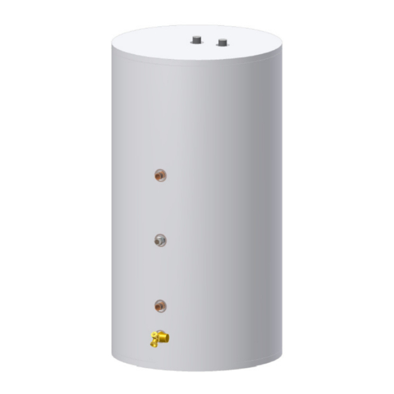
SECTION II SPECIFICATIONS Figure 1 – Heater Layout (40, 52, 75 single exchanger models) Table 1: Water Heater Dimension (Inches) MODEL 40-Gal. 9-1/2 24-5/8 35-1/4 35-1/2 52-Gal. 9-1/2 28-3/8 45-5/8 45-7/8 75-Gal. 9-1/2 28-1/4 63-7/8 64-1/8... - Page 9 Specifications continued- Figure 2 – Tank Layout (120 gallon model)
- Page 10 Specifications continued- Table 2: Water Heater Capacities Tank Cap. Coil Cap. Dry Weight Wet Weight (Gal) (Gal) (Lbs) (Lbs) MODEL 40-Gal. 52-Gal. 75-Gal. 120-Gal. 1257 Table 3: AHRI Certified Water Heater Ratings Continuous Standby Minimum Minimum First Draw Heat Output of Heat Hour Rating...
- Page 11 Specifications continued- Table 5: Water Heater Performance Hot Water Coil Heat Availability Transfer Pressure Drop MODEL (Minutes) Area (Sq Ft) (Feet of Head) 40-Gal. 6.0 @ 8 gpm 52-Gal. 10.0 6.2 @ 8 gpm 75-Gal. 14.3 10.0 6.2 @ 8 gpm 120-Gal 23.8 21.3...
-
Page 12: Iii- General Information
SECTION III GENERAL INFORMATION FEATURES This water heater contains the following features: The heat exchanger (coil) has 3/4” NPT HEAT EXCHANGER -- female fittings. These water heaters with stainless steel single-wall heat exchangers meet the Uniform Plumbing Code for installation in all potable water systems provided that: ... - Page 13 General Information continued- TEMPERATURE AND PRESSURE RELIEF VALVE WARNING Keep clear of the combination temperature and pressure relief valve discharge line outlet. The discharge may be hot enough to cause scald injury. The water is under pressure and may splash. For protection against excessive temperatures and pressure, install temperature and pressure protective equipment required by local codes, but not less than a combination temperature and pressure...
- Page 14 General Information continued- WARNING Install a discharge line so that water discharged from the temperature and pressure relief valve will exit within six (6) inches above, or any distance below, the structural floor and cannot contact any live electrical part. The discharge line is to be installed to allow for complete drainage of both the temperature and pressure relief valve and the discharge line.
-
Page 15: Iv- Pre-Installation
SECTION IV PRE-INSTALLATION UNPACKING INSPECT SHIPMENT carefully for any signs of damage. If damage is noted, do not install the product. Contact the shipper or manufacturer. All equipment is carefully manufactured, inspected, and packed. Our responsibility ceases upon delivery of the packaged water heater to the carrier in good condition. - Page 16 Pre-installation continued- NOTICE Increasing the boiler DOE heating capacity above the values listed in Table 3 will not increase the rating of the water heater. 2. Circulator Sizing – Refer to Table 5 for the corresponding pressure drop through the coil for the given model.
- Page 17 Pre-installation continued- Boiler DOE heating capacity is 100,000 Btu per hour or less, or b) When boiler output required to satisfy domestic hot water demand is at least 50% of the boiler output required to satisfy space heating demand, or When an interruption in space heating can be tolerated during a long domestic hot water draw.
- Page 18 Pre-installation continued- CAUTION Do not drop water heater. Do not bump water heater jacket against floor. Appliance Location 1. Boiler Location – Locate the indirect-fired water heater as close to the boiler as practical. 2. Fixture Locations – For fastest delivery of hot water, place the indirect-fired water heater close to points of use.
-
Page 19: V- Water Connections
SECTION V WATER CONNECTIONS WARNING FAILURE TO INSTALL AND MAINTAIN A NEW, LISTED TEMPERATURE AND PRESSURE RELIEF VALVE WILL RELEASE THE MANUFACTURER FROM ANY CLAIM WHICH MIGHT RESULT FROM EXCESSIVE TEMPERATURE AND PRESSURES. Keep clear of the temperature and pressure relief valve discharge line outlet. - Page 20 Water Connections continued- outlet are identified on the side and top of the water heater, respectively. Make the proper plumbing connections between the water heater and the plumbing system to the house. Install a shut-off valve in the cold water supply line. 2.
- Page 21 Water Connections continued- CONNECT WATER BOILER SUPPLY PIPING 1. For a space heating system that utilizes ZONE VALVES, refer to Figure 3. The indirect-fired water heater connection labeled “FROM BOILER SUPPLY” should be piped to the boiler supply piping. Mount the circulator making sure the flow arrow points toward the water heater.
- Page 22 Water Connections continued- Figure 4 - Water Boiler Piping with Circulators CONNECT STEAM BOILER SUPPLY PIPING Figure 5 represents a typical steam boiler connection diagram. Refer to the boiler installation manual or contact the boiler manufacturer for an appropriate piping diagram. The use of a union, shut-off valves, and a drain valve is recommended for future service convenience.
- Page 23 Water Connections continued- NOTICE Typical steam boiler without connections available below the water line is not recommended due to insufficient water temperature, especially during warmer months when the space heating system is not operational. Boiler water temperature at the bottom of a steam boiler can be 50°F lower than the boiler’s water temperature limit setting during such periods.
-
Page 24: Vi- Electrical Connections
SECTION VI ELECTRICAL CONNECTIONS Install electric wiring in accordance with National Electric Code or the Canadian Electrical Code and local regulations. See the boiler’s installation manual for wiring diagrams. DANGER Positively assure all electrical connections are unpowered before attempting installation or service of electrical components or connections of the water heater or building. - Page 25 Electrical Connections continued- AT NO TIME SHOULD WATER HEATER OPERATION TAKE PLACE WITHOUT THE COVER ON THE CONTROL. Figure 6 - Aquastat Control...
-
Page 26: Vii- Operating Instructions
SECTION VII OPERATING INSTRUCTIONS WARNING Water heaters are heat-producing appliances. To avoid damage or injury there must be no materials stored against the water heater, and proper care must be taken to avoid unnecessary contact (especially by children) with the water heater. UNDER NO CIRCUMSTANCES SHALL FLAMMABLE MATERIALS, SUCH AS GASOLINE OR PAINT THINNER BE USED OR STORED IN THE VICINITY OF THE WATER... - Page 27 Operating Instructions continued- WATER TEMPERATURE ADJUSTMENT WARNING SCALDING This water heater can deliver scalding temperature water at any faucet in the system. Be careful whenever using hot water to avoid scalding injury. By setting the thermostat on this water heater to obtain an increased water temperature, you may create the potential for scald injury.
- Page 28 Operating Instructions continued- CAUTION Before adjusting the aquastat, turn off all power supplied to the indirect-fired water heater. For the most energy efficient operation, adjust the aquastat for the minimum water temperature necessary to meet domestic hot water needs. Refer to Figure 8. Use a small flat screwdriver to rotate the temperature dial through the hole directly below the temperature indication window.
- Page 29 Operating Instructions continued- Adjusting to a lower temperature setting will not immediately affect water temperature. Draw sufficient water or allow the water heater to remain idle until a heat-up cycle is initiated. After the heater’s heat-up cycle is complete, check the water temperature at a faucet to determine if further adjustment is necessary.
-
Page 30: Viii- Maintenance
SECTION VIII MAINTENANCE This indirect-fired water heater is intended to provide a service life of many years. Components that require service, however, may be subject to failure. Failure to use the correct procedures or parts in these circumstances may make the water heater unsafe. The owner should arrange to have the following inspections and simple maintenance procedure performed by qualified service personnel at the frequencies suggested. - Page 31 Maintenance continued- If the temperature and pressure relief valve on the heater discharges periodically or continuously, it may be due to thermal expansion of water in a closed water supply system, or it may be due to a faulty relief valve. Thermal expansion is the normal response of water when it is heated.
-
Page 32: Ix- Troubleshooting Guide
SECTION IX TROUBLE SHOOTING GUIDE PROBLEM CAUSE SOLUTION No hot water Boiler does not Refer to boiler installation at faucet operate instructions Check main service switch Check fused disconnect Circulator does not Check power supply operate Replace as necessary Improper aquastat Turn tank aquastat to setting or appropriate setting... - Page 33 Trouble Shooting Guide continued- PROBLEM CAUSE SOLUTION Insufficient hot Aquastat setting Adjust aquastat to higher water too low setting. See Section VII Undersized boiler Rewire for priority with no priority to domestic hot water Peak use of hot Determine peak usage water is greater and compare to tank than tank storage...
-
Page 34: X- Parts List
SECTION X PARTS LIST PART NAME & DESCRIPTION 1. Temperature and Pressure 4. Nipple ¾ NPT x 2” Relief Valve 2. Aquastat Well 5. Drain/Return Valve 3. Aquastat 6. Anode... - Page 35 Contact your supplier or plumbing professional for replacement parts or contact the company at the address given on the rating plate of the water heater. Provide the part name, model, and serial numbers of the water heater when ordering parts. READ THE WARRANTY FOR A FULL EXPLANATION OF THE LENGTH OF TIME THAT PARTS AND THE WATER HEATER ARE WARRANTED.
- Page 36 NOTES:...