Table of Contents
Advertisement
Quick Links
⚠ WARNING: If the information in
this manual is not followed exactly, a fire
or explosion may result causing property
damage, personal injury or loss of life.
-- This water heater MUST NOT be
installed in any location where gasoline or
flammable vapors are likely to be present.
-- WHAT TO DO IF YOU SMELL GAS
• Do not try to light any appliance.
• Do not touch any electric switch; do not
use any phone in your building.
• Immediately call your gas supplier from
a near by phone. Follow the gas supplier's
instructions.
• If you cannot reach your gas supplier, call
the fire department.
• Installation and service must be performed
by a qualified installer, service agency, or
the gas supplier.
OAW-I-O_100161598_2000015611_Rev AA
Outdoor Armor Water
Heater Installation &
Operation Manual
Models: 151 - 286
This manual must only be used by
⚠WARNING
a qualified heating installer / service
technician. Read all instructions,
including this manual and the
Outdoor Armor Water Heater
Service Manual, before installing.
Perform steps in the order given.
Failure to comply could result in
severe personal injury, death, or
substantial property damage.
Save this manual for future reference.
Advertisement
Table of Contents

Related Manuals for Lochinvar ARMOR OAN151PM


Summary of Contents for Lochinvar ARMOR OAN151PM
- Page 1 OAW-I-O_100161598_2000015611_Rev AA Outdoor Armor Water Heater Installation & Operation Manual Models: 151 - 286 ⚠ WARNING: If the information in this manual is not followed exactly, a fire or explosion may result causing property damage, personal injury or loss of life. -- This water heater MUST NOT be installed in any location where gasoline or flammable vapors are likely to be present.
-
Page 2: Table Of Contents
Contents HAZARD DEFINITIONS ..........2 5. FIELD WIRING PLEASE READ BEFORE PROCEEDING ..... 3 Line Voltage Connections ..........24 THE OUTDOOR ARMOR WATER HEATER -- HOW IT Low Voltage Connections ..........24 WORKS ................4-5 Wiring of the Cascade ............26 RATINGS ................ -
Page 3: Please Read Before Proceeding
Outdoor Armor Water Heater Installation & Operation Manual Please read before proceeding Installer – Read all instructions, including DO NOT install units in rooms or ⚠WARNING ⚠WARNING environments that contain corrosive this manual and the Outdoor Armor Water contaminants (see Table 1B on page 9). Heater Service Manual, before installing. -
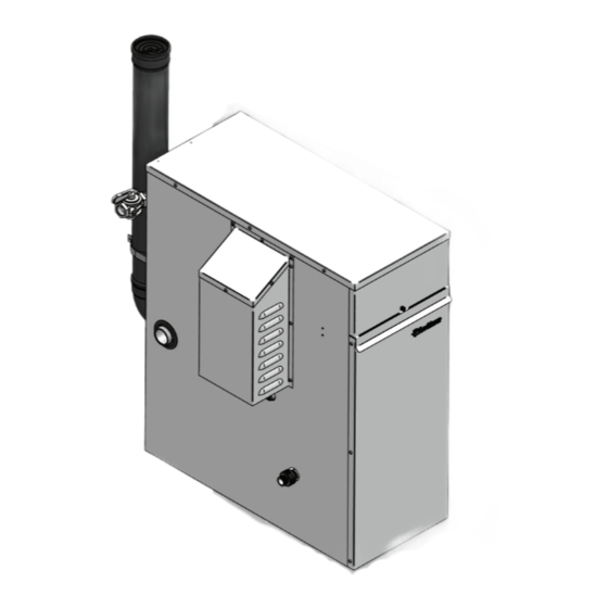
Page 4: The Outdoor Armor Water Heater -- How It
Outdoor Armor Water Heater Installation & Operation Manual The Outdoor Armor Water Heater - How it works... 21. Condensate drain connection Stainless steel heat exchanger Connects the condensate drain line to a 1/2" PVC union. Allows water to flow through specially designed coils for maximum 22. - Page 5 Outdoor Armor Water Heater Installation & Operation Manual The Outdoor Armor Water Heater - How it works... (continued) Models 151 - 201 IMG00284 IMG00287 Rear View - Models 151 - 201 Left Side (inside unit) - Models 151 - 201 IMG00360 Left Side (inside unit) - Model 286 Rear View - Model 286...
-
Page 6: Ratings
Outdoor Armor Water Heater Installation & Operation Manual Ratings LOW LEAD CONTENT Model Number Input Modulation Btu/hr Water Content Water Note: Change “N” to “L” for Gallons Connections Connections L.P. gas models. (Note 2) OAN151PM 30,000 - 150,000 1-1/4" 1/2" OAN200PM 39,800 - 199,000 1-1/4"... -
Page 7: Determine Water Heater Location
Outdoor Armor Water Heater Installation & Operation Manual Determine water heater location Installation must comply with: Do not install outdoor models directly on CAUTION • Local, state, provincial, and national codes, laws, regulations, the ground. You must install the outdoor unit on a concrete, brick, block or pressure- and ordinances. -
Page 8: Provide Clearances
Outdoor Armor Water Heater Installation & Operation Manual Determine water heater location (continued) Outdoor vent / air intake location Failure to keep the water heater area clear ⚠WARNING and free of combustible materials, gasoline The flue products discharged from the flue ⚠WARNING and other flammable liquids and vapors can outlet on the outdoor vent may be very... -
Page 9: Prevent Combustion Air Contamination
Outdoor Armor Water Heater Installation & Operation Manual Determine water heater location Prevent combustion air contamination Do not install in locations that can allow contamination of combustion air. Refer to Table 1B for products and areas which may cause contaminated combustion air. Table 1B Corrosive Contaminants and Sources Products to avoid: Spray cans containing chloro/fluorocarbons... -
Page 10: Prepare Water Heater
Outdoor Armor Water Heater Installation & Operation Manual Prepare water heater Remove water heater from wood pallet 5. Slide the flue pipe through the wall strap and insert it into the elbow. 1. After removing the outer shipping carton from the water 6. -
Page 11: Gas Conversions
Outdoor Armor Water Heater Installation & Operation Manual Prepare water heater Gas conversions Figure 2-3 Installing Propane Orifice For a water heater already installed, you ⚠WARNING must turn off gas supply, turn off power and allow the water heater to cool before proceeding. -
Page 12: System Piping
Outdoor Armor Water Heater Installation & Operation Manual System piping System water piping methods Figure 3-1 Pump Cover Installation Observe a minimum of 1/4 inch clearance around all un-insulated hot water pipes when openings around the pipes are not protected by non-combustible materials. General piping information Basic steps are listed below along with illustrations on the following pages (FIG.’s 3-5 thru 3-9), which will guide you... -
Page 13: Flow Switch Adjustment
Outdoor Armor Water Heater Installation & Operation Manual System piping (continued) Turn the sensitivity screw clockwise to increase NOTICE Figure 3-2 Flow Switch and Relief Valve Installation the flow rate required to activate the switch. Turn the sensitivity screw counterclockwise to decrease the flow rate required to activate the switch. -
Page 14: Water Chemistry
NOTICE Tank sensor: pumps shown in Table 3C are selected Lochinvar supplies a tank sensor. The tank sensor must be based on the heating of potable water with installed in the tapping provided in the lower 25% of the storage a specified water chemistry. - Page 15 Outdoor Armor Water Heater Installation & Operation Manual System piping (continued) Figure 3-5 Single Heater - Single Tank BUILDING RETURN FLOW CHECK VALVE (TYPICAL) COLD WATER SUPPLY BUILDING RECIRCULATION FILTER (IF REQUIRED SEE START-UP SECTION) MIXING VALVE EXPANSION THERMOMETER TANK HOT WATER WATER SUPPLY...
- Page 16 Outdoor Armor Water Heater Installation & Operation Manual System piping Figure 3-6 Single Heater - Single Tank (2 Temperature) FLOW CHECK BALL VALVE VALVE (TYPICAL) WATER HEATER (TYPICAL) CIRCULATOR 180° HOT HIGH TEMPERATURE THERMOMETER WATER BUILDING RETURN (TYPICAL) SUPPLY UNION 140°...
- Page 17 Outdoor Armor Water Heater Installation & Operation Manual System piping (continued) Figure 3-7 Single Heater - Double Tank BUILDING BALL VALVE RETURN (TYPICAL) FLOW CHECK VALVE (TYPICAL) BUILDING RECIRCULATION FILTER (IF REQUIRED SEE START-UP SECTION) COLD WATER SUPPLY EXPANSION TANK MIXING VALVE WATER HEATER CIRCULATOR...
- Page 18 Outdoor Armor Water Heater Installation & Operation Manual System piping Figure 3-8 Double Heater - Single Tank Number of Units Number of Units Model Model Required Pipe Sizes in NPT with Standard Pump Required Pipe Sizes in NPT with Upsized Pump 1 1/2"...
- Page 19 Outdoor Armor Water Heater Installation & Operation Manual System piping (continued) Figure 3-9 Double Heater - Double Tank Number of Units Number of Units Model Model Required Pipe Sizes in NPT with Standard Pump Required Pipe Sizes in NPT with Upsized Pump 1 1/2"...
-
Page 20: Gas Connections Connecting Gas Supply Piping
Outdoor Armor Water Heater Installation & Operation Manual Gas connections Connecting gas supply piping 3. Support piping with hangers, not by the water heater or its accessories. 1. Remove the top access panel and refer to FIG.’s 4-1 and 4-2 The gas valve and blower will not support ⚠WARNING to pipe gas to the water heater. -
Page 21: Natural Gas
Outdoor Armor Water Heater Installation & Operation Manual Gas connections (continued) Natural gas: Use two wrenches when tightening gas ⚠WARNING piping at water heater (FIG. 4-3), using Pipe sizing for natural gas one wrench to prevent the water heater gas line connection from turning. Failure 1. -
Page 22: Check Inlet Gas Supply
Outdoor Armor Water Heater Installation & Operation Manual Gas connections Table 4A Natural Gas Pipe Size Chart Capacity of Schedule 40 Metallic Pipe in Cubic Feet of Natural Gas Per Hour (based on .60 specific gravity, 0.30" w.c. pressure drop) Pipe Length of Pipe in Straight Feet Size... -
Page 23: Gas Pressure
Outdoor Armor Water Heater Installation & Operation Manual Gas connections (continued) 17. Check burner performance by cycling the system while you observe burner response. The burner should ignite promptly. Flame pattern should be stable. Turn system off and allow burner to cool, then cycle burner again to ensure proper ignition and flame characteristics. -
Page 24: Field Wiring
Outdoor Armor Water Heater Installation & Operation Manual Field wiring Installation must comply with: ELECTRICAL SHOCK HAZARD – For ⚠WARNING your safety, turn off electrical power supply before making any electrical connections 1. National Electrical Code and any other national, state, to avoid possible electric shock hazard. - Page 25 Outdoor Armor Water Heater Installation & Operation Manual Field wiring (continued) Tank thermostat Flow switch 1. Connect the tank thermostats (isolated contact only) to 1. A flow switch is used to guarantee flow through the water the tank thermostat contacts as shown in FIG. 5-3. heater before allowing it to fire.
-
Page 26: Wiring Of The Cascade
Outdoor Armor Water Heater Installation & Operation Manual Field wiring Runtime contacts The SMART SYSTEM control closes a set of dry contacts whenever the burner is running. This is typically used by Building Management Systems to verify that the water heater is responding to a call for heat. - Page 27 Outdoor Armor Water Heater Installation & Operation Manual Field wiring (continued) Figure 5-3 Low Voltage Field Wiring Connections...
-
Page 28: Condensate Disposal Condensate Drain
Outdoor Armor Water Heater Installation & Operation Manual Condensate disposal Condensate drain Use materials approved by the authority NOTICE having jurisdiction. In the absence of other authority, PVC and CPVC pipe must comply 1. This water heater is a high efficiency appliance that with ASTM D1785 or D2845. -
Page 29: Startup
Outdoor Armor Water Heater Installation & Operation Manual Check for gas leaks Start-up Before starting the water heater, and during ⚠WARNING initial operation, smell near the floor and Check/control water chemistry around the water heater for gas odorant or any unusual odor. Remove the top access panel and smell the interior of the Conduct water quality testing prior NOTICE... - Page 30 Outdoor Armor Water Heater Installation & Operation Manual Start-up Final checks before starting the water q Check vent piping and air piping heater 1. Check for gastight seal at every connection, seam of air q Read the Outdoor Armor Water Heater Service Manual piping, and vent piping.
- Page 31 Outdoor Armor Water Heater Installation & Operation Manual Start-up (continued) Figure 7-2 Operating Instructions FOR YOUR SAFETY READ BEFORE OPERATING WARNING: If you do not follow these instructions exactly, a fire or explosion may result causing property damage, personal injury, or loss of life. A.
- Page 32 Outdoor Armor Water Heater Installation & Operation Manual Start-up (continued) Check flame and combustion Set water heater operation (continued) 4. Place the water heater into the active position by pressing Set tank set point temperature the RIGHT SELECT [ON] key (FIG. 8-1, page 38). Please note that the brackets ([]) denote NOTICE screen status.
- Page 33 Outdoor Armor Water Heater Installation & Operation Manual Start-up Configuration of the cascade Set clock Please note that the brackets ([]) denote Please note that the brackets ([]) denote NOTICE NOTICE screen status. screen status. The SMART SYSTEM control has a built-in clock that it When installed in a Cascade system, the individual controls uses for its night setback feature and for logging events.
-
Page 34: Operating Information General
Outdoor Armor Water Heater Installation & Operation Manual Operating information General Protection features How the water heater operates Outlet temperature, flue temperature, and temperature rise limiting The outdoor water heater uses an advanced stainless steel heat The outlet temperature is monitored by the water heater outlet exchanger and electronic control module that allows fully temperature sensor. - Page 35 Outdoor Armor Water Heater Installation & Operation Manual Operating information Monitor external limits When the outlet temperature exceeds 200°F, the automatic high limit action occurs. The water heater shuts down until the outlet Connections are provided on the connection board for water temperature cools below 190°F, and a 60 second timer has external limits such as a flow switch and gas pressure expired.
-
Page 36: Cascade
Outdoor Armor Water Heater Installation & Operation Manual Operating information (continued) Cascade Access modes When multiple water heaters are installed, they can be User wired together in a cascade sequence. A maximum of eight water heaters can be controlled from a single control. In The user can adjust tank target temperatures by pressing the this application one water heater would be designated as the NAVIGATION dial when “$SETPOINTS”... -
Page 37: Sequence Of Operation
Outdoor Armor Water Heater Installation & Operation Manual Operating information Sequence of operation OPERATION DISPLAY 1. The control will turn on the water heater pump (always ON except in Night Setback). The flow switch and/or LWCO must close. 2. Air pressure switch and blocked drain switch must close. 3. -
Page 38: Outdoor Armor Water Heater Control Module
Outdoor Armor Water Heater Installation & Operation Manual Operating information (continued) Outdoor Armor water heater control module Use the control panel (FIG. 8-1) to set temperatures, operating conditions, and monitor water heater operation. Figure 8-1 Control Panel The information on the bottom of the display shows the functions of the two SELECT keys (on either corner), and the NAVIGATION dial (in the center): MENU = Left SELECT Key SETPOINTS = NAVIGATION Dial - Pressing Down... -
Page 39: Status Display Screens
Outdoor Armor Water Heater Installation & Operation Manual Operating information Figure 8-2 Status Display Screen Status Display Screens Section Display Description The unit has not received a call for heat from a remote thermostat STANDBY nor has it received a call for heat from a DHW thermostat. START The unit has begun a burn cycle and is checking all safety circuits. - Page 40 Outdoor Armor Water Heater Installation & Operation Manual Operating information (continued) Status Display Screens (cont’d) Section Display Description TANK: The temperature read by the tank sensor (if connected). INLET TEMP: The temperature read at the inlet to the heat exchanger. OUTLET TEMP: The temperature read at the outlet of the heat exchanger.
- Page 41 Outdoor Armor Water Heater Installation & Operation Manual Operating information Status Display Screens (cont’d) Section Display Description Turning the NAVIGATION dial will select the next or previous Status Screen. Pressing the NAVIGATION dial will show the next fault, NSB (Night Setback) trigger, or ramp delay setting.
-
Page 42: Maintenance
Outdoor Armor Water Heater Installation & Operation Manual Maintenance Maintenance and annual startup Table 9A Service and Maintenance Schedules Service technician Owner maintenance (see the following pages for instructions) General: • Address reported problems • Inspect interior; clean and vacuum if •... - Page 43 Outdoor Armor Water Heater Installation & Operation Manual Maintenance Follow the service and maintenance procedures given throughout this manual and in component literature ⚠WARNING shipped with the water heater. Failure to perform the service and maintenance could result in damage to the water heater or system.
- Page 44 Outdoor Armor Water Heater Installation & Operation Manual Maintenance (continued) Failure to inspect for the above conditions Following installation, the valve lever must ⚠WARNING ⚠WARNING and have them repaired can result in be operated AT LEAST ONCE A YEAR to severe personal injury or death.
- Page 45 Outdoor Armor Water Heater Installation & Operation Manual Maintenance Perform start-up and checks 3. Remind the owner to follow the proper shutdown procedure and to schedule an annual start-up. 1. Start water heater and perform checks and tests specified Cleaning heat exchanger in Section 7 - Start-up.
- Page 46 Outdoor Armor Water Heater Installation & Operation Manual Maintenance (continued) Check Delta T Table 9B Heat Exchanger Cleaning Kits 1. Check Delta T. Reference Section 3 - System Piping on Part Component page 16 for more information regarding Delta T. Model Number Number...
-
Page 47: Diagrams
Outdoor Armor Water Heater Installation & Operation Manual Diagrams Figure 10-1 Ladder Diagram 120VAC JUNCTION BOX NEUTRAL GROUND TERMINAL STRIP TERMINAL STRIP 120V SUPPLY "L" 120V SUPPLY "N" AW MODELS ONLY ON / OFF INTEGRATED CONTROL SWITCH X1-1 BLOWER X1-6 3.15A BUILDING X1-2... -
Page 48: Wiring Diagram
Outdoor Armor Water Heater Installation & Operation Manual Diagrams (continued) Figure 10-2 Wiring Diagram LOW VOLTAGE BOX DEPICTS 120 VAC OPTIONAL ITEMS HIGH VOLTAGE BOX DEPICTS DUAL SENSOR SINGLE HOUSING INTEGRATED CONNECTION BOARD CONTROL JUNCTION ALARM X1-3 OR/BK CONTACTS RUN-TIME PUMP CONTACTS X1-4... - Page 49 Outdoor Armor Water Heater Installation & Operation Manual NOTES...
-
Page 50: Revision Notes
Revision Notes: Revision A (ECO #C10942) initial release. Revision B (ECO #C11235) reflects updates made to the freezing conditions warnings. Revision C (ECO C12102) reflects the addition of condensate kit option information for areas that may reach below 32°F as well as a warning not to install OA 400 in these areas and Table 1A on page 8.