Table of Contents
Troubleshooting

Related Manuals for Westerbeke 15.0 MEG-60Hz


Summary of Contents for Westerbeke 15.0 MEG-60Hz
- Page 1 M U LT I - P O RT S I N G L E – P H A S E MARINE GASOLINE GENERATORS OPERATORS MANUAL 15.0 MEG-60Hz, 12.0 MEG-50Hz 20.0 MEG-60Hz, 16.0 MEG-50Hz 23.0 MEG-60Hz, 18.0 MEG-50Hz PART NUMBER 057749...
- Page 2 In no event shall Westerbeke, publishers, authors, or editors of this guide be liable for any loss of profit, or any other commercial damage caused or alleged to have been caused directly or indirectly by this document.
- Page 3 MTBE is no longer a primary concern since it is no longer available.) sludge, or gums entering or forming in the engine or fuel system is not covered by the Westerbeke Corporation limited warranty. Ethanol is a solvent and tends to clean any dirt or contaminants on contact.
-
Page 4: Table Of Contents
Operators Manual for Gasoline Generators 1 Important Safety Information C O N T E N T S 1 Important Safety Information 2 Introduction Quick Start Operators Guide ........................4 Documentation ............................4 Parts Diagram ............................5 Warranty Procedures ..........................7 Conventions Used in this Manual ...................... - Page 5 Operators Manual for Gasoline Generators 1 Important Safety Information Lay-Up Prep: Spare Parts......................... 42 How to Recommission After a Lay-Up ..................... 42 9 Generator Specifications Specifications: Engine ..........................43 Specifications: Fuel System ........................43 Specifications: Electrical System ......................43 Specifications: Air Requirements ......................43 Specifications: Cooling System ........................
- Page 6 Operators Manual for Gasoline Generators L I S T O F F I G U R E S Figure 1: Parts Diagram (12.0 MEG - 15.0 MEG) ....................5 Figure 2: Parts Diagram (16.0 MEG - 23.0 MEG) ....................6 Figure 3: Customer Identification Card .........................
-
Page 7: Important Safety Information
Operator Manual for Gasoline Generators ▪ All fuel vapors are highly explosive. Use extreme care when handling and storing fuels. Store fuel in a well-ventilated area away from spark- Important Safety Information producing equipment and out of the reach of children. ▪... - Page 8 CO poisoning is one of the major safety risks associated with exhaust gas with an appropriate CO analyzer. boating. It is a threat that must not be underestimated. Westerbeke There are two locations where exhaust gas can be sampled: multiport EFI generators are designed to dramatically reduce normal levels of CO in the engine exhaust.
- Page 9 Control System consists of engine design and precision Scientific, GFG, TPI, Teledyne, and others. manufacturing. ▪ Westerbeke recommends analyzers with a probe connected to the Engine Valve analyzer by a length of transparent tubing. They are slightly more Adjustment expensive than those with the sensor built-in to one end of the analyzer,...
-
Page 10: Introduction
Operator Manual for Gasoline Generators 2 Introduction This Westerbeke generator is a product of our many years of experience and advanced technology. We take great pride in the superior durability and dependable performance of our engines and generators. Thank you for selecting Westerbeke. -
Page 11: Parts Diagram
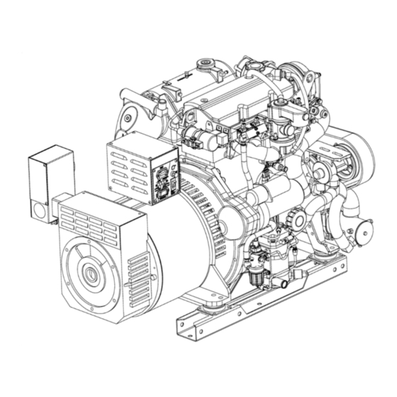
Operator Manual for Gasoline Generators 2 Introduction Parts Diagram Fig 1: Parts Diagram (12.0 MEG - 15.0 MEG) page... -
Page 12: Figure 2: Parts Diagram (16.0 Meg - 23.0 Meg)
2 Introduction Operator Manual for Gasoline Generators Fig 2: Parts Diagram (16.0 MEG - 23.0 MEG) page... -
Page 13: Warranty Procedures
2 Introduction Warranty Procedures Your Westerbeke Warranty Statement is included in the product documentation package. Complete and return the included warranty registration card or register your product online at www.westerbeke.com. You should receive your customer warranty identification card in the mail within 30 days of registering. If you do not, contact the factory and have your product model number, serial number, and in-service date available. -
Page 14: Conventions Used In This Manual
Westerbeke distributor or dealer. Checklist: Protecting Your Investment Care at the factory during assembly and thorough testing have resulted in a Westerbeke generator capable of many hours of dependable service. However, the manufacturer cannot control where the generator is installed in the vessel or how well the unit is installed, operated, and serviced in the field. -
Page 15: Amperage Drain
2.11 Spare Parts, Kits, and Accessories Certain spare parts will be needed to support and maintain your Westerbeke generator. Your local Westerbeke dealer will assist you in preparing an inventory of suggested spare parts and accessories. TIP: We also recommend carrying enough spare engine oil for an oil change and one gallon of premixed coolant for the cooling system. -
Page 16: Figure 6: Suggested Spare Parts
2 Introduction Operator Manual for Gasoline Generators For your convenience, we offer two spare part kits, each packaged in a water-tight storage case: Kit A includes the basic set of the most essential recommended spare parts. ■ Kit B includes everything in Kit A, plus additional spare parts for more extensive offshore cruising. ■... -
Page 17: Installation
If you have any doubt about the position of the water-injected exhaust elbow relative to the vessel waterline under the various operating conditions for your vessel, install a siphon-break, available from Westerbeke or your local authorized Westerbeke dealer. -
Page 18: Exhaust System Requirements
3 Installation Operator Manual for Gasoline Generators NOTE: A siphon-break requires periodic inspection and cleaning to ensure proper operation. Failure to properly maintain a siphon-break can result in catastrophic engine damage. Consult the siphon-break manufacturer for proper maintenance. Exhaust System Requirements To install exhaust system components, see the installation manual. -
Page 19: Startup And Basic Operation
5.1: Maintenance Schedule. Westerbeke does not approve or disapprove the use of synthetic oils. If synthetic oils are used, engine break-in must be performed using conventional oil. The required oil change intervals are listed in this manual and cannot be extended, even if synthetic oils are used. -
Page 20: Coolant Recovery Tank
4 Startup and Basic Operation Operator Manual for Gasoline Generators Coolant Recovery Tank A coolant recovery tank kit is supplied with each generator to allow for engine coolant expansion and contraction during engine operation without the loss of coolant and without introducing air into the cooling system. -
Page 21: How To Start And Stop The Generator
Operator Manual for Gasoline Generators 4 Startup and Basic Operation Figure 9: Fuel System How to Start and Stop the Generator 4.7.1 How to Start and Stop the Generator (Control Panel) The start/stop rocker switch is the only functional component on the generator control panel (and optional remote-control panel) used to start and stop the generator. -
Page 22: Figure 10: Control Panel Dc Circuit Breaker And Start/Stop Switch
4 Startup and Basic Operation Operator Manual for Gasoline Generators Figure 10: Control Panel DC Circuit Breaker and Start/Stop Switch 4.7.2 How to Start and Stop the Generator (Remote Control Panel) You can also perform the same steps using an optional remote-control panel. Two remote start/stop panels are available that allow for the engine/generator to be controlled from any location on the boat. -
Page 23: Safety Shutdown Switches And Leds
Operator Manual for Gasoline Generators 4 Startup and Basic Operation 4.7.4 Failure to Start The start cycle will automatically terminate if the engine fails to start. Three crank cycles can be attempted before the ECU initiates a fault and prevents further crank cycle attempts. Investigate the cause of this no-start, correct it, and reset the power to the ECU. -
Page 24: Figure 13: Oil Pressure Switch And Transducer
4 Startup and Basic Operation Operator Manual for Gasoline Generators 4.8.2 Oil Pressure Switch and Transducer Figure 13: Oil Pressure Switch and Transducer An oil pressure switch is located on the right side of the oil filter assembly. This is a normally open contact switch. It functions with the time relay circuit to ensure DC voltage to the fuel pump circuit is terminated when the unit shuts down. -
Page 25: Break-In Procedure
Operator Manual for Gasoline Generators 4 Startup and Basic Operation 4.8.5 DC Circuit Breaker The engines electrical system is protected by a 20-amp manual reset circuit breaker. An electrical overload in the wiring harness or instrument panel will trip the breaker and shut down the engine/generator. Should this occur, inspect and repair the problem. -
Page 26: Checklist: Daily Startup
4 Startup and Basic Operation Operator Manual for Gasoline Generators ❑ Inspect exhaust system connections: Inspect the connections and catalyst. ❑ Check the grounding and neutrals: Confirm systems with a neutral line are properly grounded as the system requires, and that the generator neutral is properly connected to the load neutral. In single phase systems, an incomplete or open neutral can supply the wrong line-to-neutral voltage on unbalanced loads. -
Page 27: Maintenance
Operator Manual for Gasoline Generators 5 Maintenance 5 Maintenance Maintenance Schedule The maintenance intervals specify operating hours or a time interval, whichever comes first. For example, if maintenance is due every 250 hours or six months, and you have logged 300 hours in only two months, do not delay maintenance another four months. - Page 28 5 Maintenance Operator Manual for Gasoline Generators 5.1.4 Every 100 Operating Hours or Yearly ❑ Engine Oil and Filter: Change engine oil and filter. Spark plugs: check and clean/gap/replace as needed. ❑ Air Screen/Flame Arrestor: Remove, clean and re-install screen pack. Inspect rubber sealing ring ❑...
-
Page 29: Maintenance: Fuel System
Operator Manual for Gasoline Generators 5 Maintenance Maintenance: Fuel System Incoming fuel from the water separator filter is drawn through the inlet fuel filter into the fuel module by the electric lift pump. The fuel is cooled as it circulates through the fuel module and is then pumped by the electric lift pump to the high-pressure pump module. -
Page 30: Figure 19: Harness Lift Pump Dc Auxiliary Power Adapter
5 Maintenance Operator Manual for Gasoline Generators 5.2.3 Engine Fuel Filter Periodically check the fuel connections and the bowl for leakage. Replace the filter element after the first 50 hours then follow the maintenance schedule. 5.2.4 How to Change the Engine-Mounted Fuel Filter Element Shut off the fuel supply to the generator. -
Page 31: Maintenance: Cooling System
CAUTION: Proper cooling system maintenance is critical. Many premature engine failures can be traced back to cooling system corrosion. Westerbeke marine engines are designed and equipped for fresh water (50% anti-freeze/50% distilled water) cooling. Heat produced in the engine by combustion and friction is transferred to fresh water, which circulates throughout the engine. - Page 32 5 Maintenance Operator Manual for Gasoline Generators Slowly open the manifold bleeder and let any air out. Bleeding is complete when coolant comes out of bleeder with no air. It is recommended to surround the bleeder with an absorbent cloth to prevent coolant spillage.
-
Page 33: Figure 21: Cooling System Heat Exchanger (Left) And Thermostat (Right)
Operator Manual for Gasoline Generators 5 Maintenance Figure 21: Cooling System Heat Exchanger (Left) and Thermostat (Right) 5.3.4 Cooling System Zinc Anode A zinc anode (or pencil) in the raw-water cooling circuit in the heat exchanger sacrifices itself to electrolysis action taking place in the raw-water cooling circuit, reducing the effects of electrolysis on other components of the system. -
Page 34: Maintenance: Engine
Chapter 5.1: Maintenance Schedule. Westerbeke does not approve or disapprove the use of synthetic oils. If synthetic oils are used, engine break-in must be performed using conventional oil. Oil change intervals must be as listed in 5.1: Maintenance Schedule and cannot be extended if synthetic oils are used. -
Page 35: Figure 22: Engine Oil Drain Hose (Left) And Oil Filter Assembly (Right)
Screw the filter onto the threaded oil filter stub. Where the filter contacts the base, tighten firmly by hand. TIP: Use genuine Westerbeke oil filters. Generic filters are not recommended. 5.4.3 How to Refill the Engine Oil Add fresh oil through the valve cover. -
Page 36: Figure 23: Engine Oil System Componets
5 Maintenance Operator Manual for Gasoline Generators After refilling the oil, run the engine for a few moments. Make sure there is no leakage around the new oil filter or from the oil drain system, and then stop the engine. Check the quantity of oil with the lube oil dipstick. -
Page 37: Figure 25: Air Screen/Flame Arrestor
Operator Manual for Gasoline Generators 5 Maintenance Clean using a good dish washing solution, rinse, and air dry. Inspect the seal edges. If worn, install a new flame arrestor. Figure 25: Air Screen/Flame Arrestor WARNING: The generator should never be started/operated without the air screen/flame arrestor properly installed. 5.4.6 How to Check the Engine Oil Pressure The engine oil pressure is continuously monitored by the ECU and the generator control panel when the... - Page 38 CO while the engine is running. This must be performed with a CO analyzer. WARNING : Never reuse an exhaust sealing gasket. Always replace with a new gasket. NOTE: For information on installing exhaust systems, see the Installation Manual available at www.westerbeke.com. page...
-
Page 39: Maintenance: Connections, Motors, And Circuit Breakers
Operator Manual for Gasoline Generators 5 Maintenance Figure 27: Catalyst Installation Maintenance: Connections, Motors, and Circuit Breakers Maintaining reasonable cleanliness is important to avoid corrosion on terminal board connections and rectifiers. Take steps to prevent the accumulation and build-up of salt, dust, engine exhaust particulates, and carbon, especially on insulation surfaces. - Page 40 5.5.4 AC Circuit Breaker A circuit breaker is installed on all single-phase Westerbeke generators. This circuit breaker will automatically disconnect generator power in case of an electrical overload. The circuit breaker can be manually shut off when servicing the generator to ensure that no power is being supplied into the boat.
-
Page 41: Figure 28: Be Generator Windings Schematic Diagram And Ac Terminal Connections (12.0 - 15.0 Meg)
Operator Manual for Gasoline Generators 5 Maintenance Figure 28: BE Generator Windings Schematic Diagram & AC Terminal Connections (12.0-15.0 MEG) page... -
Page 42: Figure 29: Be Generator Windings Schematic Diagram And Ac Terminal Connections (16.0 - 23.0 Meg)
5 Maintenance Operator Manual for Gasoline Generators Figure 29: BE Generator Windings Schematic Diagram & AC Terminal Connections (16.0-23.0 MEG) page... -
Page 43: Figure 30: Shore Power Transfer Switch
If the installer connects shore power to the AC circuit on your vessel, this must be done by means of a shore power transfer switch. Ship-to-shore switches are available from Westerbeke or an authorized dealer. Figure 30: Shore Power Transfer Switch Set the transfer switch shown in the diagram to the OFF position. -
Page 44: Diagnostics And Troubleshooting
The diagnostic software runs on most Microsoft Operating Systems. It requires a minimum of 128 MB of RAM. The communications cable plugs into a USB port. NOTE: The Westerbeke communications cable is unique to this diagnostic software and must be used. An incompatible cable may damage the ECU. -
Page 45: Engine Troubleshooting
Operator Manual for Gasoline Generators 6 Diagnostics and Troubleshooting Engine Troubleshooting The following troubleshooting chart describes common engine problems and possible causes. CAUTION: When servicing the engine/generator, turn off the main AC circuit breaker to disconnect all AC power. Problem: Possible Cause: Engine does not crank: 1. -
Page 46: Wiring Diagrams
7 Wiring Diagrams Operator Manual for Gasoline Generators 7 Wiring Diagrams The Wiring Diagram is available online and a printed copy is included in the standard equipment kit with your generator. Remote Start/Stop Panels Figure 32: Wiring Diagram for Start/Stop Panel with Fault Display NOTE: A 15-foot or 30-foot extension harness is also available. -
Page 47: Lay-Up And Recommissioning
Operator Manual for Gasoline Generators 8 Lay-Up and Recommissioning 8 Lay-Up and Recommissioning Many owners rely on their boatyards to prepare their craft, including engines and generators, for lay-up during the off-season or for long periods of inactivity. Others prefer to accomplish lay-up preparation themselves. The following procedures allow you to perform your own lay-up and recommissioning, or you may use them as a checklist if others do the procedures. -
Page 48: Lay-Up Prep: Raw Water Cooling Circuit
Lay-Up Prep: Spare Parts Lay-up time provides an opportunity to inspect your Westerbeke engine to see if external items such as drive belts or coolant hoses need replacement. Check your basic spares kit and order items not on hand, or replace those items used during the lay-up, such as filters and zinc anodes. -
Page 49: Generator Specifications
Operator Manual for Gasoline Generators 9 Generator Specifications 9 Generator Specifications Specifications: Engine Item Description Engine Type 4-cylinder, 4-cycle, overhead camshaft water cooled gasoline engine Bore & Stroke 2.97 x 3.22 inches (75.5 x 82.0 mm.) Total Displacement 89.6 cubic inches (1468 cc) Bearings Four (4) main bearings Combustion Chamber... -
Page 50: Specifications: Cooling System
Battery ignition 12-volt negative ground, ignition coil and spark plugs. Ignition System Distributor with ignition module and coil Spark Plug Gap 0.028-0.033 inch (0.7-0.8 mm) Spark Plug Thread 14.0 mm x 1.25 pitch Ignition Timing Mechanical/vacuum Spark Plugs Westerbeke 043071 Ignition Coil 12 volts page... -
Page 51: 9.9 Specifications: Engine Component Tightening Torque
Operator Manual for Gasoline Generators 9 Generator Specifications 9.9 Specifications: Engine Component Tightening Torque Engine Component N∙M Ft. Lbs Air Cleaner Bracket 17.2-23.6 12.7-17.4 Alternator Bracket 34.6-48.3 25.5-35.6 Alternator Flange Bolt 17.2-28.2 12.7-20.8 Alternator Strap 17.2-23.6 12.7-17.4 Camshaft Pulley Lock Bolt 43.7-60.1 32.2-44.3 Throttle Body... - Page 52 9 Generator Specifications Operator Manual for Gasoline Generators This page intentionally left blank. ©2021 Westerbeke, Inc. All Rights Reserved. Westerbeke Corporation Myles Standish Industrial Park 150 John Hancock Rd. Taunton, MA 02780-7319 USA Phone: (508) 823-7677 FAX: (508) 884-9688 www.westerbeke.com...