
Related Manuals for Black Box AlertWerks AW3000


Summary of Contents for Black Box AlertWerks AW3000
- Page 1 USER MANUAL EME800A-US, EME800A-EU ALERTWERKS AW3000 24/7 TECHNICAL SUPPORT AT 1.877.877.2269 OR VISIT BLACKBOX.COM...
-
Page 2: Chapter 1: Introduction
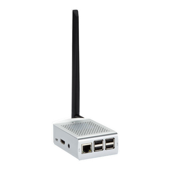
NEED HELP? LEAVE THE TECH TO US LIVE 24/7 TECHNICAL CHAPTER 1: INTRODUCTION SUPPORT 1.877.877.2269 1.1 INTRODUCTION AlertWerks™ AW3000 (AW3000) is an all-in-one-box LoRaWAN solution for wireless IoT applications. More than a gateway ® that is uploading your important data to any cloud service, it is a central unit providing full control with just a web interface. AlertWerks is open platform, allowing you to use any LoRaWAN 1.0.x sensor. -
Page 3: What's Included
NEED HELP? LEAVE THE TECH TO US LIVE 24/7 CHAPTER 1: INTRODUCTION TECHNICAL SUPPORT 1.877.877.2269 TABLE 1-1. GENERAL SPECIFICATIONS SPECIFICATION DESCRIPTION Dimensions (H X W X D) 1.3” x 2.4” x 3.9” (32 x 62 x 99 mm) Weight 6.3 oz. (180g) Rating IP20, 14 to 131ºF (-10 to +55ºC) Power... -
Page 4: Chapter 2: Installation
802.3at) or by inserting the Mini USB cable coming from a power supply with at least 5V, 3A. NOTE: A Black Box video and Linux startup messages will be displayed during the boot process. After loading the unit’s graphical interface, the unit will start a web browser and display the AW3000’s start screen. - Page 5 NEED HELP? LEAVE THE TECH TO US LIVE 24/7 CHAPTER 2: INSTALLATION TECHNICAL SUPPORT 1.877.877.2269 Right-click on the networking symbol on the top right corner of the screen. NOTE: There are two symbols displayed in this area. The one to the left of the clock is for configuring audio output.
- Page 6 NEED HELP? LEAVE THE TECH TO US LIVE 24/7 TECHNICAL CHAPTER 2: INSTALLATION SUPPORT 1.877.877.2269 A window appears, where you may change from Interface to SSID. When selecting SSID, all WiFi networks found are displayed. When selecting the interface ,you can change the IP settings of either eth0 (RJ-45) or Wlan0 (WiFi). Automatically configure empty options is DHCP.
- Page 7 NEED HELP? LEAVE THE TECH TO US LIVE 24/7 CHAPTER 2: INSTALLATION TECHNICAL SUPPORT 1.877.877.2269 After you make your selection and enter required information, try to use the Web Interface from any network device. If you selected DHCP and need to know the IP which was assigned, hover your mouse over the network symbol in the menu bar.
- Page 8 2.1.2 TROUBLESHOOTING SENSORS NOT APPEARING IN NEIGHBORHOOD. To troubleshoot sensors not appearing in Neighborhood: Black Box is defining a list of tested and certified sensors. Check with your Black Box representative if your sensor is in that list. Check the frequency setting. For the sensor it should be printed on the box or the sensor. The AW3000’s frequency setting is viewable from the Settings menu, but not changeable.
- Page 9 NEED HELP? LEAVE THE TECH TO US LIVE 24/7 CHAPTER 2: INSTALLATION TECHNICAL SUPPORT 1.877.877.2269 FIGURE 2-7: SENSOR STATUS SCREEN After the display changes to Joined: From the top left menu, select Sensors. For physical sensors, entries will appear automatically. NOTE: Most LoRaWAN sensors carry more than one value which are referred to as datapoints.
- Page 10 NEED HELP? LEAVE THE TECH TO US LIVE 24/7 TECHNICAL CHAPTER 2: INSTALLATION SUPPORT 1.877.877.2269 FIGURE 2-8: SENSOR SCREEN While this page provides current data, historical data is accumulated as the sensor transmits data. 2.1.3 DASHBOARD CREATION To create a dashboard: From top left menu, select Dashboard.
- Page 11 NEED HELP? LEAVE THE TECH TO US LIVE 24/7 CHAPTER 2: INSTALLATION TECHNICAL SUPPORT 1.877.877.2269 FIGURE 2-9: DASHBOARD CREATED WITH DEFAULT VALUES You can now create more dashboxes for other datapoints. To instructional purposes, we will use simple and single values from one datapoint, although other options are available.
- Page 12 NEED HELP? LEAVE THE TECH TO US LIVE 24/7 TECHNICAL CHAPTER 2: INSTALLATION SUPPORT 1.877.877.2269 FIGURE 2-10: DASHBOX EDITING SCREEN NOTE: One standard dashboard can carry up to 12 Dashboxes. While a dashbox’s position can be changed by Drag and Drop, resizing is only possible in the dashbox’s settings menu. Apart from Dashboards with a maximum of 12 Dashboxes, you can also change to 8x6=48, 12x9=108, or 16x9=144 Dashboxes by clicking on Edit Dashboard.
-
Page 13: Chapter 3: Definition Of Physical Sensors, Virtual Sensors, And Actions
NEED HELP? LEAVE THE TECH TO US LIVE 24/7 TECHNICAL CHAPTER 3: DEFINITION OF PHYSICAL SENSORS, VIRTUAL SUPPORT SENSORS, AND ACTIONS 1.877.877.2269 3.1 DIFFERENCE BETWEEN PHYSICAL AND VIRTUAL SENSORS In chapter 2 we worked with a physical sensor, which is a sensor that you can touch. There are also virtual sensors that you can use by configuring them. -
Page 14: Detailed Example
With another action you can enable a traffic light showing red so that people know to not enter that room. With Black Box conference and meeting room solutions, you may also move the next meeting to another room by SNMPSET. -
Page 15: Chapter 4: Creating A Virtual Sensor
NEED HELP? LEAVE THE TECH TO US LIVE 24/7 CHAPTER 4: CREATING A VIRTUAL SENSOR TECHNICAL SUPPORT 1.877.877.2269 4.1 CREATING VIRTUAL SENSORS 4.1.1 PROCEDURE TO CREATE VIRTUAL SENSOR To create a virtual sensor: Go to Webpage Sensors from the top left menu. Click on Create New Virtual sensor, which is the last entry at the left edge on that page. - Page 16 NEED HELP? LEAVE THE TECH TO US LIVE 24/7 CHAPTER 4: CREATING A VIRTUAL SENSOR TECHNICAL SUPPORT 1.877.877.2269 FIGURE 4-2: SETTING INTERVAL AND CONNECTION An entry for virtual sensors was added to the list, which previously only had physical sensors on it. To add a sensor name: Click on Edit in the line of the new virtual sensor at the right edge.
- Page 17 NEED HELP? LEAVE THE TECH TO US LIVE 24/7 CHAPTER 4: CREATING A VIRTUAL SENSOR TECHNICAL SUPPORT 1.877.877.2269 FIGURE 4-3: SENSOR SCREEN WITH ADDED VIRTUAL SENSOR INFORMATION FIGURE 4-4: EDIT VIRTUAL SENSOR SCREEN 1.877.877.2269 BLACKBOX.COM...
- Page 18 NEED HELP? LEAVE THE TECH TO US LIVE 24/7 CHAPTER 4: CREATING A VIRTUAL SENSOR TECHNICAL SUPPORT 1.877.877.2269 You can use this virtual sensor for a dashbox. Next steps: From top left menu, select dashboard. Click on Add a Dashbox. From the list of datapoints, select Ping myself.
- Page 19 Get information from IP devices. You need to know certain parameters such as OID, Community, and SNMPGET IP address. This manual can’t explain SNMP completely. Black Box offers training and videos about this topic. Traps are sent from IP devices to AW3000. In these Traps information pieces and values are normally SNMPTRAP included.
- Page 20 NEED HELP? LEAVE THE TECH TO US LIVE 24/7 CHAPTER 4: CREATING A VIRTUAL SENSOR TECHNICAL SUPPORT 1.877.877.2269 TABLE 4-1. EXPLANATION OF METHODS (CONTINUED) METHOD EXPLANATION Combine two sensors into one. Graphs will then show both. If it is a GPS tracking sensor you can use COMBINE COMBINE to get latitude and longitude to one datapoint and use the Dashbox Type Maps.
-
Page 21: Chapter 5: Creating An Action
NEED HELP? LEAVE THE TECH TO US LIVE 24/7 CHAPTER 5: CREATING AN ACTION TECHNICAL SUPPORT 1.877.877.2269 5.1 CREATING ACTIONS Creating an action is about automation. Let AW3000 do the job for you. Example using a temperature sensor: Follow steps in Chapter 2 to have a physical sensor with at least one temperature data point. Go to Sensors from the top left menu. - Page 22 NEED HELP? LEAVE THE TECH TO US LIVE 24/7 TECHNICAL CHAPTER 5: CREATING AN ACTION SUPPORT 1.877.877.2269 FIGURE 5-2: PLAY ALARM SELECTION 1.877.877.2269 BLACKBOX.COM...
-
Page 23: Action Type
NEED HELP? LEAVE THE TECH TO US LIVE 24/7 CHAPTER 5: CREATING AN ACTION TECHNICAL SUPPORT 1.877.877.2269 TABLE 5-1. EXPLANATION OF ACTION TYPES ACTION TYPE EXPLANATION Send an email. Check SMTP settings on menu settings to be able to send mails. You have the option of sending emails only once per alarm, and there is an option to have AW3000 send out an extra Email once the alarm condition ends. - Page 24 NEED HELP? LEAVE THE TECH TO US LIVE 24/7 TECHNICAL CHAPTER 5: CREATING AN ACTION SUPPORT 1.877.877.2269 Once you configure an action, it is displayed on the Sensors menu sensors right below the corresponding datapoint. That line has a blue background which changes to red as the configured timescale is reached. Apart from >, <, or =, there are many more possibilities.
-
Page 25: Chapter 6: Settings And Logs
NOTE: You will need to provide the Black Box support team with your Gateway ID (see above) and the current hour in your timezone. For example, if you call at 1:50pm and you get your unlock code at 1:55pm it will be valid for another 5 minutes. -
Page 26: Date And Time Setting
NEED HELP? LEAVE THE TECH TO US LIVE 24/7 CHAPTER 6: SETTINGS AND LOGS TECHNICAL SUPPORT 1.877.877.2269 6.1.3 DATE AND TIME SETTING Since AW3000 receives NTP broadcasts and does active NTP requests, changing the date and time setting is not needed when your AW3000 is connected to an active network or the internet. - Page 27 NEED HELP? LEAVE THE TECH TO US LIVE 24/7 CHAPTER 6: SETTINGS AND LOGS TECHNICAL SUPPORT 1.877.877.2269 6.1.9 SENSOR GROUPING This option is also disabled by default. Having many sensors, either virtual or physical, will cause a long Webpage Sensor’s list.
- Page 28 NEED HELP? LEAVE THE TECH TO US LIVE 24/7 TECHNICAL CHAPTER 6: SETTINGS AND LOGS SUPPORT 1.877.877.2269 6.1.12 SENSOR TYPES UPDATE With the update procedure for AW3000, new available payload decoders and MAC command options are downloaded and installed. This option is enabled by default. If you disable it, the payload decoders and MAC command options are not changed within the update process.
-
Page 29: Chapter 7: User Management
NEED HELP? LEAVE THE TECH TO US LIVE 24/7 CHAPTER 7: USER MANAGEMENT TECHNICAL SUPPORT 1.877.877.2269 7.1 SETTINGS Once you power up AW3000 for the first time you are logged in as a default user. The default user is iot with the password iot. Once you click on User Management from top left menu, you have the ability to change that setting. -
Page 30: Chapter 8: Obtaining A World Map Of Install Sites
NEED HELP? LEAVE THE TECH TO US LIVE 24/7 CHAPTER 8: OBTAINING A WORLD MAP OF INSTALL SITES TECHNICAL SUPPORT 1.877.877.2269 8.1 HOW TO OBTAIN A WORLD MAP OF YOUR INSTALLATION SITES Now that you have your IoT network in place using AW3000, you may want to extend the system. See Chapter 11: Tips and Tricks to learn how to use a common database for multiple AW3000 units. - Page 31 NEED HELP? LEAVE THE TECH TO US LIVE 24/7 CHAPTER 8: OBTAINING A WORLD MAP OF INSTALL SITES TECHNICAL SUPPORT 1.877.877.2269 FIGURE 8-2: EDIT SCREEN Moving datapoints from one group into another works by using Edit to change the Group Name for that datapoint. The main group and the sub group, separated by a space, make the group name.
- Page 32 NEED HELP? LEAVE THE TECH TO US LIVE 24/7 CHAPTER 8: OBTAINING A WORLD MAP OF INSTALL SITES TECHNICAL SUPPORT 1.877.877.2269 FIGURE 8-3: CHANGING A GROUP NAME After you have your groups set up and sorted according to your preference with GPS coordinates, change to dashboard and select Add a dashboard.
- Page 33 NEED HELP? LEAVE THE TECH TO US LIVE 24/7 CHAPTER 8: OBTAINING A WORLD MAP OF INSTALL SITES TECHNICAL SUPPORT 1.877.877.2269 FIGURE 8-4: ENTERING A NEW GROUP NAME 1.877.877.2269 BLACKBOX.COM...
-
Page 34: Chapter 9: Customizing Dashboards And Dashboxes With Images
NEED HELP? LEAVE THE TECH TO US LIVE 24/7 TECHNICAL CHAPTER 9: CUSTOMIZING DASHBOARDS AND SUPPORT DASHBOXES WITH IMAGES 1.877.877.2269 You should now see a screen similar to this: FIGURE 8-5: SAMPLE MAP SCREEN The MAP is centered for your site and zoomed acordingly. For these sites you can now define Jump Points. A jump point indicates which dashboard should be presented once that site is clicked. - Page 35 NEED HELP? LEAVE THE TECH TO US LIVE 24/7 TECHNICAL CHAPTER 9: CUSTOMIZING DASHBOARDS AND SUPPORT DASHBOXES WITH IMAGES 1.877.877.2269 9.1 CHOOSING IMAGES FOR DASHBOARDS AND DASHBOXES Apart from having a world map for your installation sites, having floorplans and application drawings with jump points are possible.
- Page 36 NEED HELP? LEAVE THE TECH TO US LIVE 24/7 TECHNICAL CHAPTER 9: CUSTOMIZING DASHBOARDS AND SUPPORT DASHBOXES WITH IMAGES 1.877.877.2269 FIGURE 9-2: EDITING AN IMAGE In a new browser window the FileDesigner is started. FIGURE 9-3: FILE DESIGNER SCREEN 1.877.877.2269 BLACKBOX.COM...
- Page 37 NEED HELP? LEAVE THE TECH TO US LIVE 24/7 TECHNICAL CHAPTER 9: CUSTOMIZING DASHBOARDS AND SUPPORT DASHBOXES WITH IMAGES 1.877.877.2269 In the given screenshot example, two objects are already defined. To create your design: Click on Add Object in the top right. Select a group or a single sensor from a group.
-
Page 38: Chapter 10: Combining Alertwerks Wired And Alertwerks Aw3000
LIVE 24/7 TECHNICAL CHAPTER 10: COMBINING ALERTWERKS WIRED AND SUPPORT ALERTWERKS AW3000 1.877.877.2269 10.1 CHOOSING IMAGES FOR DASHBOARDS AND DASHBOXES In many projects both platforms will be combined, since a wired IoT System delivers continuous sensor data, especially when using with legacy protocols, such as ModBus or dry contacts, AlertWerks™ wired has some advantages over a wireless system. -
Page 39: Chapter 11: Tips And Tricks
You need to have know how to do this in PHP programing and you need to have certain knowledge about your sensor. If that is the case, visit http://<youripofalertwerksiotweb>/sensortypes.php. If you do not know how to do that, Black Box can offer a paid and managed service, since Black Box technical support will not support problems caused by improper programming. - Page 40 CAUTION: Do not plug the sd card into a Windows(C) PC. Doing so will corrupt the image, and you will need to order a new prepared SD Card from your Black Box representative. 11.1.7 CHANGING THE DATABASE TO MY OWN DATABASE OR HOW TO DO REDUNDANCY AND LORAWAN WIDE AREA NETWORKS The settings menu allows you to change the database in its location.
- Page 41 NEED HELP? LEAVE THE TECH TO US LIVE 24/7 TECHNICAL CHAPTER 11: TIPS AND TRICKS SUPPORT 1.877.877.2269 TABLE 11-1. TYPES OF DASHBOXES WHEN SELECTING A DATAPOINT TYPE DESCRIPTION Graph This gives you a graph. You can also define the time scope. This gives you a tacho.
-
Page 42: Data Storage
11.1.15 UNLOCK CODE The unlock code is provided to you by a Black Box tech support team member. The Black Box tech support team member needs to know the EUI64 ID of your unit. You can view that on the start screen or in settings. - Page 43 The unlock code is just for one purpose: to change the frequency setting. The unlock code is only valid for one hour and will only be issued when Black Box’s technical support determines that it is necessary. 11.1.16 INTERACTIVE DASHBOARDS You may encounter situations where you want to have interactive dashboards.
- Page 44 NEED HELP? LEAVE THE TECH TO US LIVE 24/7 TECHNICAL CHAPTER 11: TIPS AND TRICKS SUPPORT 1.877.877.2269 FIGURE 11-2: SCREEN WITH ON CLICK GO TO SETTING This field lets you specify which dashboard is called up when that dashbox is clicked by someone without privileges to amend dashboards.
- Page 45 NEED HELP? LEAVE THE TECH TO US LIVE 24/7 TECHNICAL CHAPTER 11: TIPS AND TRICKS SUPPORT 1.877.877.2269 After clicking the Pre Provisioning icon, you can copy and paste text into the field shown with AppEUI, DevEUI, Appkey, and name seperated by a semicolon. Using the CSV Export function within Excel will provide you with the necessary file. These sensors will be configured for AW3000 (or the AW3000 domain) accordingly.
- Page 46 NEED HELP? LEAVE THE TECH TO US LIVE 24/7 TECHNICAL CHAPTER 11: TIPS AND TRICKS SUPPORT 1.877.877.2269 11.1.20 DASHBOX MAPS You should feed the DashBox MAPS with a virtual sensor doing “COMBINE” since the dashbox needs latitude and longitude to display a valid GPS location. NOTE: Only the viewer of the webpage needs access to the internet;...
- Page 47 NEED HELP? LEAVE THE TECH TO US LIVE 24/7 TECHNICAL NOTES SUPPORT 1.877.877.2269 1.877.877.2269 BLACKBOX.COM...
- Page 48 NEED HELP? LEAVE THE TECH TO US LIVE 24/7 TECHNICAL NOTES SUPPORT 1.877.877.2269 1.877.877.2269 BLACKBOX.COM...
-
Page 49: Appendix A: Regulatory Information
NEED HELP? LEAVE THE TECH TO US LIVE 24/7 APPENDIX A: REGULATORY INFORMATION TECHNICAL SUPPORT 1.877.877.2269 A.1 FCC STATEMENT This equipment has been tested and found to comply with the regulations for a Class B digital device, pursuant to Part 15 of the FCC Rules. These limits are designed to provide reasonable protection against harmful interference when the equipment is operated in a commercial environment. -
Page 50: Nom Statement
NEED HELP? LEAVE THE TECH TO US LIVE 24/7 TECHNICAL APPENDIX A: REGULATORY INFORMATION SUPPORT 1.877.877.2269 A.4 NOM STATEMENT 1. Todas las instrucciones de seguridad y operación deberán ser leídas antes de que el aparato eléctrico sea operado. 2. Las instrucciones de seguridad y operación deberán ser guardadas para referencia futura. 3. -
Page 51: Appendix B: Disclaimer/Trademarks
B.1 DISCLAIMER Black Box Corporation shall not be liable for damages of any kind, including, but not limited to, punitive, consequential or cost of cover damages, resulting from any errors in the product information or specifications set forth in this document and Black Box Corporation may revise this document at any time without notice. - Page 52 NEED HELP? LEAVE THE TECH TO US LIVE 24/7 TECHNICAL SUPPORT 1.877.877.2269 © COPYRIGHT 2022. BLACK BOX CORPORATION. ALL RIGHTS RESERVED. EN_IOT_MANUAL_EME800A-US_EME800A-EU_REV2_2301.PDF...