
Related Manuals for Black Box EME160A-UC


Summary of Contents for Black Box EME160A-UC
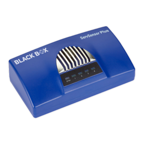
- Page 1 USER MANUAL EME160A, EME160A-UC, EME161A-R2 ALERTWERKS GATEWAY 4-PORT 24/7 TECHNICAL SUPPORT AT 1.877.877.2269 OR VISIT BLACKBOX.COM...
-
Page 2: Table Of Contents
NEED HELP? LEAVE THE TECH TO US LIVE 24/7 TABLE OF CONTENTS TECHNICAL SUPPORT 1.877.877.2269 1. SPECIFICATIONS .............................................4 2. OVERVIEW ..............................................5 2.1 Introduction ..............................................5 2.2 Features ................................................5 2.3 What’s Included ............................................6 2.4 Hardware Description ..........................................6 2.4.1 Back Panel: Ports ..............................................6 2.4.2 Top Panel: Status LEDs ...........................................7 2.4.3 Side Panel: Reset Button ..........................................8 3. - Page 3 5.5.4 Logic ...................................................98 5.5.5 SNMP Trap Receiver ...........................................100 5.6 Macro Description for Actions ....................................104 6. TROUBLESHOOTING ........................................105 APPENDIX A. EME160A-UC ......................................106 APPENDIX B. REGULATORY INFORMATION ................................107 B.1 FCC Statement ............................................107 B.2 NOM Statement ........................................... 108 APPENDIX C. DISCLAIMER/TRADEMARKS ................................109 C.1 Disclaimer ..............................................
-
Page 4: Specifications
NEED HELP? LEAVE THE TECH TO US LIVE 24/7 CHAPTER 1: SPECIFICATIONS TECHNICAL SUPPORT 1.877.877.2269 TABLE 1-1. GATEWAY SPECIFICATIONS SPECIFICATION DESCRIPTION (4) RJ-45 sensor ports for connecting AlertWerks sensors Inputs (1) RJ-45 Ethernet 10/100 ports Outputs (4) RJ-45 sensor ports (These ports can carry configurable output signals [0 VDC/5 VDC].) Number of Users (1) Power LED, (1) Network Connectivity LED, (4) Sensor Status LEDS;... -
Page 5: Overview
Š Send encrypted SNMP Trap and Email Notifications Š Supports four Intelligent Sensors Š EME160A: Two sensor ports enabled by default. Unlock all four ports with unlock code: EME160A-UC Š Notification Wizards Š Wide range of available sensors ... -
Page 6: What's Included
NEED HELP? LEAVE THE TECH TO US LIVE 24/7 CHAPTER 2: OVERVIEW TECHNICAL SUPPORT 1.877.877.2269 2.3 WHAT’S INCLUDED Your package should contain the following items. If anything is missing or damaged, contact lack Box Technical Support at 877-877-2269 or techsupport@blackbox.com Š... -
Page 7: Top Panel: Status Leds
NEED HELP? LEAVE THE TECH TO US LIVE 24/7 CHAPTER 2: OVERVIEW TECHNICAL SUPPORT 1.877.877.2269 2.4.2 TOP PANEL: STATUS LEDS Figure 2-2 shows the LEDs on the top panel of the AlertWerks Gateway . Table 2-2 describes their functions. FIGURE 2-2. TOP PANEL: STATUS LEDS TABLE 2-2. -
Page 8: Side Panel: Reset Button
NEED HELP? LEAVE THE TECH TO US LIVE 24/7 CHAPTER 2: OVERVIEW TECHNICAL SUPPORT 1.877.877.2269 2.4.3 SIDE PANEL: RESET BUTTON There are specific commands you can send to the unit by holding the Reset button for a specified amount of time. Use a straightened paperclip to press Reset. -
Page 9: Configuration
NEED HELP? LEAVE THE TECH TO US LIVE 24/7 CHAPTER 3: CONFIGURATION TECHNICAL SUPPORT 1.877.877.2269 3.1 SETTING UP THE UNIT’S IP ADDRESS NOTE: The units ship with the passwords enabled. The default log in for the web interface is: Username: admin Password: public Every unit is shipped with the default IP address of 192.168.0.100 First, we will go through the process of changing this IP address to fit your own network configuration. -
Page 10: How To Add A Secondary Ip Address To The Computer's Lan Card
NEED HELP? LEAVE THE TECH TO US LIVE 24/7 CHAPTER 3: CONFIGURATION TECHNICAL SUPPORT 1.877.877.2269 3.1.2 HOW TO ADD A SECONDARY IP ADDRESS TO THE COMPUTER’S LAN CARD You can do this via the GUI by opening the LAN connection’s properties: FIGURE 3-1. -
Page 11: Web Graphical User Interface (Gui)
NEED HELP? LEAVE THE TECH TO US LIVE 24/7 CHAPTER 4: WEB GRAPHICAL USER INTERFACE (GUI) TECHNICAL SUPPORT 1.877.877.2269 4.1 SUMMARY PAGE Figure 4-1 shows the summary page. FIGURE 4-1. SUMMARY PAGE This is the Summary page with Sensor Status and the Event Log, with the Sensor Graph enabled. The Event Log contains all entries from the “All Events”... - Page 12 NEED HELP? LEAVE THE TECH TO US LIVE 24/7 CHAPTER 4: WEB GRAPHICAL USER INTERFACE (GUI) TECHNICAL SUPPORT 1.877.877.2269 FIGURE 4-2. SENSOR INFORMATION WINDOW In the Summary page’s Sensors Information window you can do the following: Š Directly acknowledge a sensor’s status, and put the sensor offline. ...
-
Page 13: Graph Feature
NEED HELP? LEAVE THE TECH TO US LIVE 24/7 CHAPTER 4: WEB GRAPHICAL USER INTERFACE (GUI) TECHNICAL SUPPORT 1.877.877.2269 Š Enable/disable graph data collection per sensor, and display the graph display window for the Summary page. FIGURE 4-5. GRAPH DISPLAY WINDOW We’ll explain the Graph feature in more detail next. - Page 14 NEED HELP? LEAVE THE TECH TO US LIVE 24/7 CHAPTER 4: WEB GRAPHICAL USER INTERFACE (GUI) TECHNICAL SUPPORT 1.877.877.2269 FIGURE 4-7. GRAPH FORMATS DROPDOWN MENU You can choose to export the graph data in selected formats by clicking on the icon on the right. The file will be downloaded automatically and assigned a file name that will contain the sensor’s name, IP address of the unit, and the date and time.
-
Page 15: System Page
NEED HELP? LEAVE THE TECH TO US LIVE 24/7 CHAPTER 4: WEB GRAPHICAL USER INTERFACE (GUI) TECHNICAL SUPPORT 1.877.877.2269 FIGURE 4-9. SENSORS’ DROP-DOWN MENU To change to a different sensor’s graph, choose it from the drop-down menu. NOTE: You can only choose a sensor here that you’ve already enabled the graph data collection for. 4.2 SYSTEM PAGE Figure 4-1 shows the summary page. - Page 16 NEED HELP? LEAVE THE TECH TO US LIVE 24/7 CHAPTER 4: WEB GRAPHICAL USER INTERFACE (GUI) TECHNICAL SUPPORT 1.877.877.2269 in the previous screen, you can change general settings for the device. The unit’s firmware version is shown in the Description field, and the System Name/Location/Contact options are user configurable.
-
Page 17: Language Management
NEED HELP? LEAVE THE TECH TO US LIVE 24/7 CHAPTER 4: WEB GRAPHICAL USER INTERFACE (GUI) TECHNICAL SUPPORT 1.877.877.2269 FIGURE 4-13. SNMP OID OF GENERAL PAGE You can use OIDs for SNMP calls and in custom scripts, or for setting up the unit for monitoring by a third party NMS software such as WhatsUpGold or Paessler. - Page 18 NOTE: Whenever you upload or install a custom language file, it will overwrite the old file. Only one additional language is supported. For separately downloadable language files, contact Black Box Technical Support. Select a language from the drop-down menu Install New Language.
- Page 19 NEED HELP? LEAVE THE TECH TO US LIVE 24/7 CHAPTER 4: WEB GRAPHICAL USER INTERFACE (GUI) TECHNICAL SUPPORT 1.877.877.2269 FIGURE 4-17. CONFIRMATION WINDOW Wait until the language is downloaded and installed. FIGURE 4-18. INSTALLING LANGUAGE MESSAGE The unit will notify you about the successful language change, and will change the language of the Web UI. You can switch back to English by selecting it from the drop-down list on the General page, then press Save.
- Page 20 NEED HELP? LEAVE THE TECH TO US LIVE 24/7 CHAPTER 4: WEB GRAPHICAL USER INTERFACE (GUI) TECHNICAL SUPPORT 1.877.877.2269 FIGURE 4-20. LANGUAGE SCREEN, CUSTOM LANGUAGE NOTE: The official language files are also included in the firmware update packages. You can also edit the chosen language directly in the Web UI, if you choose Edit Language. 1.877.877.2269 BLACKBOX.COM...
- Page 21 NEED HELP? LEAVE THE TECH TO US LIVE 24/7 CHAPTER 4: WEB GRAPHICAL USER INTERFACE (GUI) TECHNICAL SUPPORT 1.877.877.2269 FIGURE 4-21. EDIT LANGUAGE IN WEB UI If the custom language file is present, you can select it from the drop-down list on the General page. FIGURE 4-22.
-
Page 22: Date/Time
NEED HELP? LEAVE THE TECH TO US LIVE 24/7 CHAPTER 4: WEB GRAPHICAL USER INTERFACE (GUI) TECHNICAL SUPPORT 1.877.877.2269 4.2.3 DATE/TIME FIGURE 4-23. DATE/TIME OPTION The system date and time with time zone is user configurable, with NTP server synchronization. If the unit is connected to EMEMS, then it will sync with the NTP service. -
Page 23: Network
NEED HELP? LEAVE THE TECH TO US LIVE 24/7 CHAPTER 4: WEB GRAPHICAL USER INTERFACE (GUI) TECHNICAL SUPPORT 1.877.877.2269 4.2.4 NETWORK FIGURE 4-25. NETWORK OPTION The unit’s MAC ID is displayed here, and all user configurable options for IPv4 with fixed IP or DHCP client mode. 1.877.877.2269 BLACKBOX.COM... -
Page 24: Vpn
NEED HELP? LEAVE THE TECH TO US LIVE 24/7 CHAPTER 4: WEB GRAPHICAL USER INTERFACE (GUI) TECHNICAL SUPPORT 1.877.877.2269 4.2.5 VPN FIGURE 4-26. VPN SCREEN This feature requires a separate license. You can read more details about the licensing later in this manual. This feature is used by connecting the AlertWerks Gateway to the VPN server. -
Page 25: Smtp
NEED HELP? LEAVE THE TECH TO US LIVE 24/7 CHAPTER 4: WEB GRAPHICAL USER INTERFACE (GUI) TECHNICAL SUPPORT 1.877.877.2269 4.2.6 SMTP FIGURE 4-28. SMTP SCREEN The SMTP server configuration options are shown here; it’s required to be set up for the Email actions. Fill out all parameters;... -
Page 26: Snmp
NEED HELP? LEAVE THE TECH TO US LIVE 24/7 CHAPTER 4: WEB GRAPHICAL USER INTERFACE (GUI) TECHNICAL SUPPORT 1.877.877.2269 4.2.7 SNMP FIGURE 4-30. SNMP PAGE The SNMP service configuration options are shown here; it is required for SNMP operations. SNMPv1 is enabled by default, with community password “public”. Scroll down for SNMPv3 options. -
Page 27: Snmpv3
NEED HELP? LEAVE THE TECH TO US LIVE 24/7 CHAPTER 4: WEB GRAPHICAL USER INTERFACE (GUI) TECHNICAL SUPPORT 1.877.877.2269 4.2.8 SNMPV3 FIGURE 4-31. SNMP PAGE The SNMPv3 options can be found by scrolling down on the SNMP page. This feature requires a separate license. You can read more details about the licensing in this manual. The table below shows a quick description of each setting. -
Page 28: Server Integration
NEED HELP? LEAVE THE TECH TO US LIVE 24/7 CHAPTER 4: WEB GRAPHICAL USER INTERFACE (GUI) TECHNICAL SUPPORT 1.877.877.2269 4.2.9 SERVER INTEGRATION FIGURE 4-32. SERVER INTEGRATION SCREEN If the unit has been added to the EMEMS console, the server’s IP address will be displayed here. User configurable options are the APS port and keep-alive period. -
Page 29: Services
NEED HELP? LEAVE THE TECH TO US LIVE 24/7 CHAPTER 4: WEB GRAPHICAL USER INTERFACE (GUI) TECHNICAL SUPPORT 1.877.877.2269 4.2.10 SERVICES FIGURE 4-33. SERVICES SCREEN You can close or change the ports used to access the unit’s web interface, disable HTTP and enable HTTPS only, which can also be set to be used as default. - Page 30 NEED HELP? LEAVE THE TECH TO US LIVE 24/7 CHAPTER 4: WEB GRAPHICAL USER INTERFACE (GUI) TECHNICAL SUPPORT 1.877.877.2269 When you select the file for uploading, you’ll get a warning if the file is not in .PEM format: FIGURE 4-34. UPLOAD CERTIFICATE SCREEN The .PEM file is the private key + certificate combined.
-
Page 31: Modbus
NEED HELP? LEAVE THE TECH TO US LIVE 24/7 CHAPTER 4: WEB GRAPHICAL USER INTERFACE (GUI) TECHNICAL SUPPORT 1.877.877.2269 FIGURE 4-36. SITE NOT SECURE SCREEN 4.2.11 MODBUS MODBUS RTU is a non-proprietary serial communications protocol that is widely used in the process control industry actuation. - Page 32 NEED HELP? LEAVE THE TECH TO US LIVE 24/7 CHAPTER 4: WEB GRAPHICAL USER INTERFACE (GUI) TECHNICAL SUPPORT 1.877.877.2269 FIGURE 4-37. MODBUS TCP SCREEN 1.877.877.2269 BLACKBOX.COM...
-
Page 33: Password Checking
NEED HELP? LEAVE THE TECH TO US LIVE 24/7 CHAPTER 4: WEB GRAPHICAL USER INTERFACE (GUI) TECHNICAL SUPPORT 1.877.877.2269 4.2.12 PASSWORD CHECKING FIGURE 4-38. PASSWORD CHECKING SCREEN Password checking for the Web UI can be turned on/off here, along with the option for specifying the password for the different user access levels. -
Page 34: Maintenance
NEED HELP? LEAVE THE TECH TO US LIVE 24/7 CHAPTER 4: WEB GRAPHICAL USER INTERFACE (GUI) TECHNICAL SUPPORT 1.877.877.2269 WEB UI USER ACCESS LEVELS AND PERMISSIONS Admin - full access to all settings, system and notification configurations Viewer - read-only guest access for every page User - full access to most settings except for those which are the system-related such as network In detail, the User access level provides these permissions in addition to the Viewer level: Š... -
Page 35: Heartbeat Messages
NEED HELP? LEAVE THE TECH TO US LIVE 24/7 CHAPTER 4: WEB GRAPHICAL USER INTERFACE (GUI) TECHNICAL SUPPORT 1.877.877.2269 On the System Maintenance page, the following options are available: Š Clear Event Logs: clears all logged events. Š Restore Original Settings: removes all customized settings and returns the unit to factory defaults—you can also ... -
Page 36: License Management
NEED HELP? LEAVE THE TECH TO US LIVE 24/7 CHAPTER 4: WEB GRAPHICAL USER INTERFACE (GUI) TECHNICAL SUPPORT 1.877.877.2269 4.2.15 LICENSE MANAGEMENT FIGURE 4-42. LICENSE MANAGEMENT SCREEN Here you can manage the purchased licenses for specific features on the unit. For example you can request SNMPv3 license by clicking on the Request License button. -
Page 37: About
CHAPTER 4: WEB GRAPHICAL USER INTERFACE (GUI) TECHNICAL SUPPORT 1.877.877.2269 4.2.16 ABOUT Black Box EME160A FIGURE 4-43. ABOUT SCREEN This page shows information about the Manufacturing Date, Ethernet MAC ID, and System Description, which are important when you request support. -
Page 38: Sensors Page
NEED HELP? LEAVE THE TECH TO US LIVE 24/7 CHAPTER 4: WEB GRAPHICAL USER INTERFACE (GUI) TECHNICAL SUPPORT 1.877.877.2269 4.3 SENSORS PAGE FIGURE 4-44. SENSORS PAGE On this page, you can view all sensors connected to the unit per port. Non-connected sensors will be also displayed, until you re-attach or manually remove them from the configuration. -
Page 39: General Options For All Sensors
NEED HELP? LEAVE THE TECH TO US LIVE 24/7 CHAPTER 4: WEB GRAPHICAL USER INTERFACE (GUI) TECHNICAL SUPPORT 1.877.877.2269 4.4 GENERAL OPTIONS FOR ALL SENSORS You can change the following general options for all sensors: Disable Auto Sense, Choose Sensor Type, Offline a Sensor and Smart Sensor Recovery. -
Page 40: Choose Sensor Type
NEED HELP? LEAVE THE TECH TO US LIVE 24/7 CHAPTER 4: WEB GRAPHICAL USER INTERFACE (GUI) TECHNICAL SUPPORT 1.877.877.2269 4.4.2 CHOOSE SENSOR TYPE FIGURE 4-48. SENSOR TYPE DROP-DOWN MENU You can pre-configure a specific sensor type if needed, for example if you put the sensor offline before. 4.4.3 OFFLINE A SENSOR FIGURE 4-49. -
Page 41: Smart Sensor Recovery
NEED HELP? LEAVE THE TECH TO US LIVE 24/7 CHAPTER 4: WEB GRAPHICAL USER INTERFACE (GUI) TECHNICAL SUPPORT 1.877.877.2269 4.4.4 SMART SENSOR RECOVERY FIGURE 4-51. SMART SENSOR RECOVERY BUTTON This feature will be used only for the new Smart Sensor type. The firmware can be updated on these sensors automatically, and if the upgrade has failed for some reason and the sensor becomes unresponsive, with this option you can recover them to the default firmware. -
Page 42: Change Continuous Time
NEED HELP? LEAVE THE TECH TO US LIVE 24/7 CHAPTER 4: WEB GRAPHICAL USER INTERFACE (GUI) TECHNICAL SUPPORT 1.877.877.2269 4.4.5 CHANGE CONTINUOUS TIME FIGURE 4-53. CONTINUOUS TIME SCREEN The following advanced functions are for setting the time frame in which the system should delay a notification being triggered when a sensor gives a reading that exceeds the thresholds (high warning, normal, etc). -
Page 43: Virtual Sensors
NEED HELP? LEAVE THE TECH TO US LIVE 24/7 CHAPTER 4: WEB GRAPHICAL USER INTERFACE (GUI) TECHNICAL SUPPORT 1.877.877.2269 4.5 VIRTUAL SENSORS FIGURE 4-54. VIRTUAL SENSORS SCREEN On this page, you can configure the Virtual Sensors. The first 5 sensors are free, if you need to use more you can purchase additional licenses (see the Licensing section in this manual). -
Page 44: Example Sensor Configuration
NEED HELP? LEAVE THE TECH TO US LIVE 24/7 CHAPTER 4: WEB GRAPHICAL USER INTERFACE (GUI) TECHNICAL SUPPORT 1.877.877.2269 4.6 EXAMPLE SENSOR CONFIGURATION Below we’ll show the configuration of 2 sensor types: the Temperature/Humidity and a Relay sensor. The configuration of these 2 types of sensors covers most settings that can be configured for other sensor types. 4.6.1 TEMPERATURE/HUMIDITY SENSOR Click on the sensor port where the sensor is connected to open the sensor’s configuration. - Page 45 NEED HELP? LEAVE THE TECH TO US LIVE 24/7 CHAPTER 4: WEB GRAPHICAL USER INTERFACE (GUI) TECHNICAL SUPPORT 1.877.877.2269 FIGURE 4-57. SENSOR STATE CHANGED SCREEN NOTE: the Humidity sensor has the same configuration options as the Temperature sensor. 1.877.877.2269 BLACKBOX.COM...
- Page 46 NEED HELP? LEAVE THE TECH TO US LIVE 24/7 CHAPTER 4: WEB GRAPHICAL USER INTERFACE (GUI) TECHNICAL SUPPORT 1.877.877.2269 ADVANCED SENSOR CONFIGURATION FOR TEMPERATURE/HUMIDITY SENSORS FIGURE 4-58. ADVANCED SENSOR CONFIGURATION SCREEN Fields in above screen: Š Units: Changes units from °C to °F or vice versa. ...
- Page 47 NEED HELP? LEAVE THE TECH TO US LIVE 24/7 CHAPTER 4: WEB GRAPHICAL USER INTERFACE (GUI) TECHNICAL SUPPORT 1.877.877.2269 Š Reading Offset: The Reading Offset feature is a calibration tool. If you wish to calibrate the temperature sensor, for example, you could enter an offset value of 5.
-
Page 48: Relay Sensor
NEED HELP? LEAVE THE TECH TO US LIVE 24/7 CHAPTER 4: WEB GRAPHICAL USER INTERFACE (GUI) TECHNICAL SUPPORT 1.877.877.2269 4.6.2 RELAY SENSOR Click on the sensor port where the sensor is connected to open the sensor’s configuration. NOTE: Another way of accessing this page is to click on the sensor from the Summary page. FIGURE 4-60. - Page 49 NEED HELP? LEAVE THE TECH TO US LIVE 24/7 CHAPTER 4: WEB GRAPHICAL USER INTERFACE (GUI) TECHNICAL SUPPORT 1.877.877.2269 ADVANCED SENSOR CONFIGURATION FOR RELAY SENSORS FIGURE 4-61. ADVANCED SENSOR CONFIGURATION SCREEN Š Sensor Control: FIGURE 4-62. SENSOR CONTROL ACTION DROP-DOWN MENU This button allows you to manually control the relay by controlling the cycle of the relay in an on-off-on or an off-on- off cycle.
- Page 50 NEED HELP? LEAVE THE TECH TO US LIVE 24/7 CHAPTER 4: WEB GRAPHICAL USER INTERFACE (GUI) TECHNICAL SUPPORT 1.877.877.2269 Click on the Edit button next to a selected calendar to modify it. FIGURE 4-64. CALENDAR FILTER SCREEN Blue cells means that the notification is on, white cells means it’s off. FIGURE 4-65.
-
Page 51: Managing Rack Maps
NEED HELP? LEAVE THE TECH TO US LIVE 24/7 CHAPTER 4: WEB GRAPHICAL USER INTERFACE (GUI) TECHNICAL SUPPORT 1.877.877.2269 4.7 MANAGING RACK MAPS You can add a Rack Map as a graphical representation of your server rack, and to display and record the temperature of the airflow within your server cabinets. - Page 52 NEED HELP? LEAVE THE TECH TO US LIVE 24/7 CHAPTER 4: WEB GRAPHICAL USER INTERFACE (GUI) TECHNICAL SUPPORT 1.877.877.2269 FIGURE 4-68. ADD RACK MAP SCREEN After created, you can drag and drop the Rack Map to a desktop. You can add Temperature sensors on a Rack Map. Simply drag and drop the desired sensor from your unit’s sensor list, as shown below.
-
Page 53: Firmware Upgrade Through The Web Ui
NEED HELP? LEAVE THE TECH TO US LIVE 24/7 CHAPTER 4: WEB GRAPHICAL USER INTERFACE (GUI) TECHNICAL SUPPORT 1.877.877.2269 4.8 FIRMWARE UPGRADE THROUGH THE WEB UI The firmware upgrade process is very simple and straight-forward. FIGURE 4-70. SYSTEM/MAINTENANCE PAGE Open the System/Maintenance page and click on the Upgrade button at the System Firmware Upgrade section. FIGURE 4-71. - Page 54 NEED HELP? LEAVE THE TECH TO US LIVE 24/7 CHAPTER 4: WEB GRAPHICAL USER INTERFACE (GUI) TECHNICAL SUPPORT 1.877.877.2269 This will start the Upgrade page. Choose the firmware file from your PC and click on Upgrade to start the process. The firmware file for the AlertWerks Gateway has the following format: spplus-1.0.1804.bin - where 1.0.1804 is the build version.
- Page 55 NEED HELP? LEAVE THE TECH TO US LIVE 24/7 CHAPTER 4: WEB GRAPHICAL USER INTERFACE (GUI) TECHNICAL SUPPORT 1.877.877.2269 FIGURE 4-74. UPGRADE COMPLETED SCREEN The unit will reboot at the end of the upgrade. Click on the Refresh button to reload the Web UI. 1.877.877.2269 BLACKBOX.COM...
-
Page 56: Configuring The Built-In Notifications
NEED HELP? LEAVE THE TECH TO US LIVE 24/7 CHAPTER 5: CONFIGURING THE BUILT-IN NOTIFICATIONS TECHNICAL SUPPORT 1.877.877.2269 This chapter covers all of the built-in notifications on the AlertWerks Gateway and how to configure them. 5.1 EVENTS The Events page contains all logged events that the unit stores. It’s functioning like a categorized syslog, where you can search for a specific event, and also export the logged entries to a file. -
Page 57: Events By Category
NEED HELP? LEAVE THE TECH TO US LIVE 24/7 CHAPTER 5: CONFIGURING THE BUILT-IN NOTIFICATIONS TECHNICAL SUPPORT 1.877.877.2269 You can filter the events by type, by clicking on the tabs. In this picture we’ve chosen to display only the System events. EVENTS BY CATEGORY Š... - Page 58 NEED HELP? LEAVE THE TECH TO US LIVE 24/7 CHAPTER 5: CONFIGURING THE BUILT-IN NOTIFICATIONS TECHNICAL SUPPORT 1.877.877.2269 FIGURE 5-4. EVENT LOG The unit’s Summary page also shows the Event Log, which contains all entries from the “All Events” category. The last 30 entries are shown, but if you’re scrolling down the list, more events (30 more) will be loaded automatically.
-
Page 59: Notifications
NEED HELP? LEAVE THE TECH TO US LIVE 24/7 TECHNICAL CHAPTER 5: CONFIGURING THE BUILT-IN NOTIFICATIONS SUPPORT 1.877.877.2269 5.2 NOTIFICATIONS If you set up a notification, you can define the action to take when a sensor gives a reading beyond your previously set thresholds. -
Page 60: Create An Action With The Action Wizard
NEED HELP? LEAVE THE TECH TO US LIVE 24/7 CHAPTER 5: CONFIGURING THE BUILT-IN NOTIFICATIONS TECHNICAL SUPPORT 1.877.877.2269 5.2.2 CREATE AN ACTION WITH THE ACTION WIZARD FIGURE 5-7. ACTION WIZARD SCREEN This is the Action Wizard’s welcome page; the supported Web UI configurable actions are shown. Select one to configure and click Next. - Page 61 NEED HELP? LEAVE THE TECH TO US LIVE 24/7 CHAPTER 5: CONFIGURING THE BUILT-IN NOTIFICATIONS TECHNICAL SUPPORT 1.877.877.2269 NOTE: When using the RJ-45 I/O Dry Contacts, they need to be connected to the unit before they can be configured, and have to be in the Output direction. If you click on the Finish and Setup Notification button, this will launch the Link Notification Wizard where you can use the new action for making a notification.
- Page 62 NEED HELP? LEAVE THE TECH TO US LIVE 24/7 CHAPTER 5: CONFIGURING THE BUILT-IN NOTIFICATIONS TECHNICAL SUPPORT 1.877.877.2269 For the I/O Dry Contacts, you can choose to manually control the sensor from the Advanced tab using the Sensor Control button. FIGURE 5-12.
-
Page 63: Email Action Setup
NEED HELP? LEAVE THE TECH TO US LIVE 24/7 CHAPTER 5: CONFIGURING THE BUILT-IN NOTIFICATIONS TECHNICAL SUPPORT 1.877.877.2269 5.2.4 EMAIL ACTION SETUP You can use the Email Action to send a notification by email when a sensor reaches a certain threshold. FIGURE 5-15. - Page 64 NEED HELP? LEAVE THE TECH TO US LIVE 24/7 CHAPTER 5: CONFIGURING THE BUILT-IN NOTIFICATIONS TECHNICAL SUPPORT 1.877.877.2269 FIGURE 5-17. ENTER EMAIL NAME AND MESSAGE For all possible macro values (dynamic text values starting with $), you can see a detailed list at the end of this chapter. FIGURE 5-18.
-
Page 65: Relay Action Setup
NEED HELP? LEAVE THE TECH TO US LIVE 24/7 CHAPTER 5: CONFIGURING THE BUILT-IN NOTIFICATIONS TECHNICAL SUPPORT 1.877.877.2269 5.2.5 RELAY ACTION SETUP You can use the Relay Action to control a relay when a sensor reaches a certain threshold. FIGURE 5-19. RELAY INFORMATION NOTE: The relay needs to be connected to the unit before it can be configured. - Page 66 NEED HELP? LEAVE THE TECH TO US LIVE 24/7 CHAPTER 5: CONFIGURING THE BUILT-IN NOTIFICATIONS TECHNICAL SUPPORT 1.877.877.2269 You’ll have the following options for controlling the relay with the action. FIGURE 5-21. RELAY CONTROL OPTIONS If you click on the Finish and Setup Notification button, this will launch the Link Notification Wizard where you can use the new action for making a notification.
-
Page 67: Siren Action Setup
NEED HELP? LEAVE THE TECH TO US LIVE 24/7 CHAPTER 5: CONFIGURING THE BUILT-IN NOTIFICATIONS TECHNICAL SUPPORT 1.877.877.2269 5.2.6 SIREN ACTION SETUP You can use the Siren Action to turn on the siren and strobe light when a sensor reaches a certain threshold. FIGURE 5-24. - Page 68 NEED HELP? LEAVE THE TECH TO US LIVE 24/7 CHAPTER 5: CONFIGURING THE BUILT-IN NOTIFICATIONS TECHNICAL SUPPORT 1.877.877.2269 On the Sensors page, you can specify additional settings for the siren as shown next. FIGURE 5-26. SENSORS PAGE, SIREN SETTINGS You can choose to manually control the sensor from the Advanced tab using the Sensor Control button. 1.877.877.2269 BLACKBOX.COM...
-
Page 69: Sms Action Setup
NEED HELP? LEAVE THE TECH TO US LIVE 24/7 CHAPTER 5: CONFIGURING THE BUILT-IN NOTIFICATIONS TECHNICAL SUPPORT 1.877.877.2269 5.2.7 SMS ACTION SETUP You can use the SMS Action to send a notification by SMS when a sensor reaches a certain threshold. The unit can send an SMS, or voice alert to many different phone numbers, but you can specify only one phone number per action when setting it up. - Page 70 NEED HELP? LEAVE THE TECH TO US LIVE 24/7 CHAPTER 5: CONFIGURING THE BUILT-IN NOTIFICATIONS TECHNICAL SUPPORT 1.877.877.2269 FIGURE 5-28. SMS MESSAGE SCREEN After clicking “Next,” you will get a page where you can input the SMS message. Press the “Customize” button and the fields will re-write in a format that will allow for an automated SMS that will display the sensor information.
- Page 71 NEED HELP? LEAVE THE TECH TO US LIVE 24/7 CHAPTER 5: CONFIGURING THE BUILT-IN NOTIFICATIONS TECHNICAL SUPPORT 1.877.877.2269 FIGURE 5-30. RETRY SCREEN These parameters set the maximum number of times to send the SMS notification and the time interval between each notification.
-
Page 72: Snmp Trap Action Setup
NEED HELP? LEAVE THE TECH TO US LIVE 24/7 CHAPTER 5: CONFIGURING THE BUILT-IN NOTIFICATIONS TECHNICAL SUPPORT 1.877.877.2269 5.2.8 SNMP TRAP ACTION SETUP You can use the SNMP Trap Action to send a notification (Trap message) to your SNMP Trap Receiver server when a sensor reaches a certain threshold. - Page 73 NEED HELP? LEAVE THE TECH TO US LIVE 24/7 CHAPTER 5: CONFIGURING THE BUILT-IN NOTIFICATIONS TECHNICAL SUPPORT 1.877.877.2269 FIGURE 5-32. SNMP TRAP TYPE SCREEN A different trap message is sent for each sensor type, such as temperature, humidity, and switch. The trap messages include VarBind fields that include the current sensor status (Normal, Critical High, Warning High, Critical Low, Warning Low, and sensorError), the current sensor value, the level exceeded, the sensor index, the sensor name, and the sensor description.
- Page 74 NEED HELP? LEAVE THE TECH TO US LIVE 24/7 CHAPTER 5: CONFIGURING THE BUILT-IN NOTIFICATIONS TECHNICAL SUPPORT 1.877.877.2269 SNMP v2c Action FIGURE 5-34. SNMP INFORMATION SCREEN Enter your Destination IP Address and Community; the default SNMP port is automatically selected. FIGURE 5-35.
- Page 75 NEED HELP? LEAVE THE TECH TO US LIVE 24/7 CHAPTER 5: CONFIGURING THE BUILT-IN NOTIFICATIONS TECHNICAL SUPPORT 1.877.877.2269 FIGURE 5-36. SNMP TRAP TYPE SCREEN A different trap message is sent for each sensor type such as temperature, humidity, and switch. The trap messages include VarBind fields that include the current sensor status (Normal, Critical High, Warning High, Critical Low, Warning Low, and sensorError), the current sensor value, the level exceeded, the sensor index, the sensor name, and the sensor description.
- Page 76 NEED HELP? LEAVE THE TECH TO US LIVE 24/7 CHAPTER 5: CONFIGURING THE BUILT-IN NOTIFICATIONS TECHNICAL SUPPORT 1.877.877.2269 SNMP v3 action Only SNMPv3 provides secure SNMP communication. The previous versions are considered unsecure and unencrypted. This feature requires a separate license. FIGURE 5-38.
- Page 77 NEED HELP? LEAVE THE TECH TO US LIVE 24/7 CHAPTER 5: CONFIGURING THE BUILT-IN NOTIFICATIONS TECHNICAL SUPPORT 1.877.877.2269 FIGURE 5-39. SNMP DETAILS SCREEN You can choose the packet to be sent between SNMP Trap or Inform packet. Configure the settings for authentication, and access privileges. Next, we’ll give a quick description of each setting.
- Page 78 NEED HELP? LEAVE THE TECH TO US LIVE 24/7 CHAPTER 5: CONFIGURING THE BUILT-IN NOTIFICATIONS TECHNICAL SUPPORT 1.877.877.2269 FIGURE 5-40. SNMP TRAP TYPE SCREEN A different trap message is sent for each sensor type such as temperature, humidity, and switch. The trap messages include VarBind fields that include the current sensor status (Normal, Critical High, Warning High, Critical Low, Warning Low, and sensorError), the current sensor value, the level exceeded, the sensor index, the sensor name, and the sensor description.
-
Page 79: Telephone Call Action Setup
NEED HELP? LEAVE THE TECH TO US LIVE 24/7 CHAPTER 5: CONFIGURING THE BUILT-IN NOTIFICATIONS TECHNICAL SUPPORT 1.877.877.2269 FIGURE 5-41. RETRY SCREEN These parameters set the maximum number of times to send the trap notification and the time interval between each notification. - Page 80 NEED HELP? LEAVE THE TECH TO US LIVE 24/7 CHAPTER 5: CONFIGURING THE BUILT-IN NOTIFICATIONS TECHNICAL SUPPORT 1.877.877.2269 FIGURE 5-42. TELEPHONE CALL INFORMATION SCREEN After typing in your phone number, click Next. You can specify only one phone number per action. FIGURE 5-43.
- Page 81 NEED HELP? LEAVE THE TECH TO US LIVE 24/7 CHAPTER 5: CONFIGURING THE BUILT-IN NOTIFICATIONS TECHNICAL SUPPORT 1.877.877.2269 FIGURE 5-44. ACKNOWLEDGEMENT SCREEN If Speech Acknowledgement is selected, the user will be requested to dial 1 on their phone when prompted in the call to confirm their acknowledgement.
-
Page 82: Example Notification Setup: Sms Notification
NEED HELP? LEAVE THE TECH TO US LIVE 24/7 CHAPTER 5: CONFIGURING THE BUILT-IN NOTIFICATIONS TECHNICAL SUPPORT 1.877.877.2269 FIGURE 5-46. RETRY SCREEN These parameters set the maximum number of times to send the call notification and the time interval between each notification. - Page 83 NEED HELP? LEAVE THE TECH TO US LIVE 24/7 CHAPTER 5: CONFIGURING THE BUILT-IN NOTIFICATIONS TECHNICAL SUPPORT 1.877.877.2269 On the Notifications menu, we click on Add. This will start the Link Notification Wizard. You can set up any notification with any action with the same steps as in this example. FIGURE 5-49.
- Page 84 NEED HELP? LEAVE THE TECH TO US LIVE 24/7 CHAPTER 5: CONFIGURING THE BUILT-IN NOTIFICATIONS TECHNICAL SUPPORT 1.877.877.2269 FIGURE 5-51. SELECT STATUS AND ACTION SCREEN Next, we choose the status High Critical for the sensor, and use the previously created SMS Action. You could also select multiple statuses for a sensor.
- Page 85 NEED HELP? LEAVE THE TECH TO US LIVE 24/7 CHAPTER 5: CONFIGURING THE BUILT-IN NOTIFICATIONS TECHNICAL SUPPORT 1.877.877.2269 FIGURE 5-53. CONTINUOUS TIME SCREEN We set the continuous time as 2 seconds — this means the sensor’s state has to remain at least 2 seconds in the chosen state before the notification runs.
-
Page 86: Heartbeat Messages
NEED HELP? LEAVE THE TECH TO US LIVE 24/7 CHAPTER 5: CONFIGURING THE BUILT-IN NOTIFICATIONS TECHNICAL SUPPORT 1.877.877.2269 All actions have an option Escalation. With this, you could specify additional actions to run after the initial action, with the specified time. Use the Add and Remove buttons to add or remove escalated actions. - Page 87 NEED HELP? LEAVE THE TECH TO US LIVE 24/7 CHAPTER 5: CONFIGURING THE BUILT-IN NOTIFICATIONS TECHNICAL SUPPORT 1.877.877.2269 FIGURE 5-58. HEARTBEAT MESSAGES SCREEN In the first step, you can choose the type of the heartbeat notification, which can be Email, SMS, or SNMP Trap. In our example we’ll use Email notification.
- Page 88 NEED HELP? LEAVE THE TECH TO US LIVE 24/7 CHAPTER 5: CONFIGURING THE BUILT-IN NOTIFICATIONS TECHNICAL SUPPORT 1.877.877.2269 FIGURE 5-60. SENSORS SCREEN In this step, you can choose one or more sensor’s status and reading to include in the heartbeat message. Select at least one sensor.
- Page 89 NEED HELP? LEAVE THE TECH TO US LIVE 24/7 CHAPTER 5: CONFIGURING THE BUILT-IN NOTIFICATIONS TECHNICAL SUPPORT 1.877.877.2269 FIGURE 5-62. SCHEDULE TASK BY MINUTE Finally, choose a schedule for the heartbeat message. This picture shows the by-minute schedule. You can choose between Minute, Day, Week, Month. We’ll also show the configuration for all of them next.
- Page 90 NEED HELP? LEAVE THE TECH TO US LIVE 24/7 CHAPTER 5: CONFIGURING THE BUILT-IN NOTIFICATIONS TECHNICAL SUPPORT 1.877.877.2269 FIGURE 5-64. SCHEDULE TASK BY WEEK This is the by-weekly schedule. FIGURE 5-65. SCHEDULE TASK BY MONTH This is the by-monthly schedule. 1.877.877.2269 BLACKBOX.COM...
- Page 91 NEED HELP? LEAVE THE TECH TO US LIVE 24/7 CHAPTER 5: CONFIGURING THE BUILT-IN NOTIFICATIONS TECHNICAL SUPPORT 1.877.877.2269 FIGURE 5-66. HEARTBEAT TASK ON LIST When you’ve finished the wizard, it will appear in the list. You can edit or remove the task, and reset the success counter. NOTE: You can define multiple heartbeat notification tasks with different schedule or notification methods.
-
Page 92: Virtual Sensors
NEED HELP? LEAVE THE TECH TO US LIVE 24/7 CHAPTER 5: CONFIGURING THE BUILT-IN NOTIFICATIONS TECHNICAL SUPPORT 1.877.877.2269 5.5 VIRTUAL SENSORS FIGURE 5-68. VIRTUAL SENSORS SCREEN Virtual Sensors can be a very powerful tool in your monitoring system. On the AlertWerks gateways, you can have up to 32 of these virtual sensors and they allow for a multitude of applications. -
Page 93: Boolean
NEED HELP? LEAVE THE TECH TO US LIVE 24/7 CHAPTER 5: CONFIGURING THE BUILT-IN NOTIFICATIONS TECHNICAL SUPPORT 1.877.877.2269 5.5.1 BOOLEAN FIGURE 5-70. BOOLEAN VIRTUAL SENSOR Boolean works on the virtual sensor by checking the status of, for example, 2 to 3 sensors and if the sensors’ statuses match that of the setting, they will return a value of 1. -
Page 94: Snmp Get
NEED HELP? LEAVE THE TECH TO US LIVE 24/7 CHAPTER 5: CONFIGURING THE BUILT-IN NOTIFICATIONS TECHNICAL SUPPORT 1.877.877.2269 In this example picture, the virtual sensor’s status will be critical when any of the Humidity/Temperature/Dry Contact sensors will have a high/low/critical status. NOTE: If you connect an expansion board, you’ll be able to select sensors from the expansion board also. - Page 95 NEED HELP? LEAVE THE TECH TO US LIVE 24/7 CHAPTER 5: CONFIGURING THE BUILT-IN NOTIFICATIONS TECHNICAL SUPPORT 1.877.877.2269 OID: The OID for what you wish to monitor. If, for example, you want to poll temperature data from an AlertWerks Gateway with a Temp sensor on Port 1, then you would use the following OID: 1.3.6.1.4.1.3854.1.2.2.1.16.1.3.0 Where the last digit (0) is Port 1.
- Page 96 NEED HELP? LEAVE THE TECH TO US LIVE 24/7 CHAPTER 5: CONFIGURING THE BUILT-IN NOTIFICATIONS TECHNICAL SUPPORT 1.877.877.2269 FIGURE 5-77. ANALOG SENSOR STYLE SCREEN Value Multiplier gives you the choice to multiply the reading value by a given number. Unit text: example, if measuring temperature “degrees centigrade” or if measuring humidity “percentage humidity” etc.
-
Page 97: Virtual Ping
NEED HELP? LEAVE THE TECH TO US LIVE 24/7 CHAPTER 5: CONFIGURING THE BUILT-IN NOTIFICATIONS TECHNICAL SUPPORT 1.877.877.2269 5.5.3 VIRTUAL PING FIGURE 5-79. VIRTUAL PING SCREEN With the ping sensor, you can set up ping monitoring of a network device or server. FIGURE 5-80. -
Page 98: Logic
NEED HELP? LEAVE THE TECH TO US LIVE 24/7 CHAPTER 5: CONFIGURING THE BUILT-IN NOTIFICATIONS TECHNICAL SUPPORT 1.877.877.2269 FIGURE 5-82. TRUE/FALSE STATE VALUE Normal State Value: TRUE = sensor will be Normal status if ping successful (otherwise it will be in Critical status) FALSE = sensor will be Normal status if ping times out (otherwise it will be in Critical status) FIGURE 5-83. - Page 99 NEED HELP? LEAVE THE TECH TO US LIVE 24/7 CHAPTER 5: CONFIGURING THE BUILT-IN NOTIFICATIONS TECHNICAL SUPPORT 1.877.877.2269 The logic will ignore all other intermediate physical sensor statuses and only changes the virtual sensor’s state back if it exactly matches the specified physical sensor status (RESET Source Sensor). FIGURE 5-85.
-
Page 100: Snmp Trap Receiver
NEED HELP? LEAVE THE TECH TO US LIVE 24/7 CHAPTER 5: CONFIGURING THE BUILT-IN NOTIFICATIONS TECHNICAL SUPPORT 1.877.877.2269 There’s also support for Dual Sensors FlipFlop logic. FIGURE 5-87. TRIGGER LOGIC MENU FIGURE 5-88. DUAL SENSORS FLIPFLOP LOGIC EXAMPLE In this mode, you can choose two sensors for monitoring. It has AND relation between them, and only changes the virtual sensor’s state if there’s an exact match for these statuses. - Page 101 NEED HELP? LEAVE THE TECH TO US LIVE 24/7 CHAPTER 5: CONFIGURING THE BUILT-IN NOTIFICATIONS TECHNICAL SUPPORT 1.877.877.2269 FIGURE 5-90. SNMP TRAP RECEIVER PARAMETERS Normally the Trap will have six OIDs, you can specify the specific OID from them with the Specific option. Example: In our example shown next, the Trap is sent by the Motion Sensor on Port 5 of our sensorProbe unit.
- Page 102 NEED HELP? LEAVE THE TECH TO US LIVE 24/7 CHAPTER 5: CONFIGURING THE BUILT-IN NOTIFICATIONS TECHNICAL SUPPORT 1.877.877.2269 If it is set to bothTypeTraps(3), device will send the trap two times, specific value will show sensor type and show sensor type and port (Specific value of Motion Sensor port 5 is 305 and 30).
- Page 103 NEED HELP? LEAVE THE TECH TO US LIVE 24/7 CHAPTER 5: CONFIGURING THE BUILT-IN NOTIFICATIONS TECHNICAL SUPPORT 1.877.877.2269 If you choose an Analog sensor style, you will get a slightly different menu. FIGURE 5-94. ANALOG SENSOR STYLE The configuration values are similar to other analog type sensors. 1.877.877.2269 BLACKBOX.COM...
-
Page 104: Macro Description For Actions
NEED HELP? LEAVE THE TECH TO US LIVE 24/7 CHAPTER 5: CONFIGURING THE BUILT-IN NOTIFICATIONS TECHNICAL SUPPORT 1.877.877.2269 5.6 MACRO DESCRIPTION FOR ACTIONS FIGURE 5-95. MACRO HELP WINDOW NOTE: This macro help window is also available from the Web UI when you click on the Macro Description button. 1.877.877.2269 BLACKBOX.COM... -
Page 105: Troubleshooting
9. If you can put the unit online this would be the fastest way for us to solve the problem. 10. What is the MAC ID of the unit? Contact Black Box Technical Support at 877-877-2269 or techsupport@blackbox.com if you have any further technical questions or problems. -
Page 106: Appendix A. Eme160A-Uc
EME160A units are shipped with two RJ-45 sensors ports unlocked. The remaining two sensors ports will be LOCKED and unusable unless the EME160A-UC is purchased. The EME160A is field upgradable with the EME160A-UC unlock code. To unlock the ports your units MAC ID must be provided. -
Page 107: Appendix B. Regulatory Information
NEED HELP? LEAVE THE TECH TO US LIVE 24/7 APPENDIX B: REGULATORY INFORMATION TECHNICAL SUPPORT 1.877.877.2269 B.1 FCC STATEMENT Class B Digital Device. This equipment has been tested and found to comply with the limits for a Class B computing device pursuant to Part 15 of the FCC Rules. -
Page 108: Nom Statement
NEED HELP? LEAVE THE TECH TO US LIVE 24/7 APPENDIX B: REGULATORY INFORMATION TECHNICAL SUPPORT 1.877.877.2269 B.2 NOM STATEMENT 1. Todas las instrucciones de seguridad y operación deberán ser leídas antes de que el aparato eléctrico sea operado. 2. Las instrucciones de seguridad y operación deberán ser guardadas para referencia futura. 3. -
Page 109: Appendix C. Disclaimer/Trademarks
C.1 DISCLAIMER Black Box Corporation shall not be liable for damages of any kind, including, but not limited to, punitive, consequential or cost of cover damages, resulting from any errors in the product information or specifications set forth in this docu- ment and Black Box Corporation may revise this document at any time without notice. - Page 110 NEED HELP? LEAVE THE TECH TO US LIVE 24/7 TECHNICAL SUPPORT 1.877.877.2269 © COPYRIGHT 2020, 2022. BLACK BOX CORPORATION. ALL RIGHTS RESERVED. EME160A_EME160A-UC_EME161A-R2_USER_REV3.PDF...