Table of Contents
Advertisement
Owner's Manual
Thank you and congratulations on your choice of the Roland Trigger MIDI Converter
TMC-6.
Before using this unit, carefully read the sections entitled: "USING THE
UNIT SAFELY" (p. 2–3) and "IMPORTANT NOTES" (p. 4). These sections
provide important information concerning the proper operation of the unit.
Additionally, in order to feel assured that you have gained a good grasp of
every feature provided by your new unit, Owner's manual should be read in its
entirety. The manual should be saved and kept on hand as a convenient
reference.
203 220
* GS (
) is a registered trademark of Roland Corporation.
*
All product names mentioned in this document are trademarks or registered
trademarks of their respective owners.
202
Copyright © 2002 ROLAND CORPORATION
All rights reserved. No part of this publication may be reproduced in any
form without the written permission of ROLAND CORPORATION.
Advertisement
Table of Contents

Related Manuals for Roland TMC-6


Summary of Contents for Roland TMC-6
- Page 1 Owner’s Manual Thank you and congratulations on your choice of the Roland Trigger MIDI Converter TMC-6. Before using this unit, carefully read the sections entitled: “USING THE UNIT SAFELY” (p. 2–3) and “IMPORTANT NOTES” (p. 4). These sections provide important information concerning the proper operation of the unit.
- Page 2 (except when this manual provides specific instructions directing you to do so). Refer all servicing to your retailer, the nearest Roland Service Center, or an authorized Roland distributor, as listed on the "Information" page. • Never use or store the unit in places that are: •...
- Page 3 (water, soft drinks, etc.) to penetrate the unit. 012b • Immediately turn the power off, remove the AC adaptor from the outlet, and request servicing by your retailer, the nearest Roland Service Center, or an authorized Roland distributor, as listed on the “Information” page when: •...
-
Page 4: Important Notes
• Unfortunately, it may be impossible to restore the contents of data that was stored in the unit’s memory once it has been lost. Roland Corporation assumes no liability concerning such loss of data. • Use a reasonable amount of care when using the unit’s buttons, sliders, or other controls;... -
Page 5: Table Of Contents
Rear panel... 7 Turning the Power On and Off ... 7 Connecting the TMC-6...8 Attaching the TMC-6 to a Drum Stand... 8 Connecting Drum Pads ... 8 Trigger Inputs and the Pads You Can Use... 8 Restoring the Factory Settings (FACTORY RESET)...10 If a Message Error Appears ... -
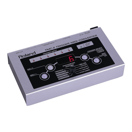
Page 6: Panel Descriptions
“Parameter List” (p. 24). 4. EDIT Button Pressed to switch among the Play, Edit, and Copy modes. You can distinguish among the TMC-6’s different modes by checking the status of button. Unlit: Play mode (used for normal performance mode when the power is turned on) -
Page 7: Rear Panel
These accept connection of the optional pads, drum triggers, foot switches, or other such devices that you wish to connect to the TMC-6 (p. 8). For more detailed information on each trigger input, refer to “Trigger Inputs and the Pads You Can Use” (p. 8). -
Page 8: Connecting The Tmc-6
Connecting the TMC-6 Attaching the TMC-6 to a Drum Stand You can attach the TMC-6 to a drum stand (optional). 1. Attach the stand holder to the TMC-6. Using the provided screws, attach the holder so the unit is oriented as shown in the diagram. - Page 9 Turning on the power with the TRIG 6/HH CTRL switch set to TRIG 6 automatically enables use of pads with the TMC-6. Connecting a Hi-Hat Control Pedal 1. Connect the hi-hat control pedal (FD-7, FD-6) to the TRIG 6/HH CTRL jack.
-
Page 10: Restoring The Factory Settings (Factory Reset)
Press the [EDIT] button to put the TMC-6 in a state allowing Factory Reset to be carried out. Press the [EDIT] button again to execute Factory Reset. -
Page 11: Making The Pad Settings
This setting ensures that pads are correctly recognized. 2. With the MIDI CHANNEL parameter, set the MIDI channel used by the TMC-6 for transmitting data so it matches the MIDI channel that the external MIDI device or other equipment uses to receive data. -
Page 12: Specifying A Trigger Type
Making the Pad Settings Selecting from the TMC-6’s panel (Trigger Chase OFF) 1. Press the [EDIT] button to make its indicator light. This takes you into Edit mode. 2. If the [TRIGGER SELECT] button is not lit, it indicates that Trigger Chase is OFF. -
Page 13: Editing Midi Parameters
Editing MIDI Parameters Once you have connected the pads and selected the appropriate trigger type, then match the MIDI channel that the TMC-6 uses to transmit data to the MIDI channel used by the external MIDI device, and specify the MIDI note numbers used to produce sounds when the pads are struck. -
Page 14: Example Of Connections And Settings
Here is an introductory example of actual settings using the TMC-6. Adding a Pad to a Drum Module You can use the TMC-6 to increase the number of pads connected to a TD-10 or other sound generator. The following describes how pads would be added if you were using a TD-10. - Page 15 2. Confirm which of the TD-10 and TMC-6 the pad is connected to. When you strike the pads connected to the TD-10, the TD-10’s trigger indicators flash. When you strike the pads connected to the TMC-6, the TMC-6’s trigger input indicators flash.
- Page 16 TD-8/6’s percussion part. If the drum kit part and percussion part share the same MIDI channel, the drum kit instrument is played when you strike the TMC-6’s pad, so set the percussion part to a different MIDI channel (for example, Ch 11). See “Setting the MIDI Channel for a Part”...
- Page 17 Module” in the TD-8 Owner’s Manual (p. 156), “Using the TD-6 As a Sound Module” in the TD-6 Owner’s Manual (p. 107)) • Connect a pad or foot switch to the TMC-6 and transmit a Program Change with the MIDI channel and program number for the TD-8/6 percussion set.
-
Page 18: Advanced Methods Of Using Pads
If TRIG 2 is already being used for another pad, you can still connect a PD- 80R/PD-120 to two of the TMC-6’s TRIGGER INPUTS (such as 3 and 4 or 5 and 6) with an optional cable (PCS-31) and have rim shots played as a separate tone. -
Page 19: Connecting The Cy-15R Or Cy12-R/C (Three Way Triggering Function)
Edge Shot * Head-side tones for the trigger input 2, 4, and 6 cannot be sounded. If you use two cables to connect the CY-15R or CY-12R/C to the TMC-6 without using the “ the sounds of both the bow and edge to be heard. Furthermore, trigger chase will not occur correctly. -
Page 20: Connecting A Foot Switch
■ Attaching the Acoustic Drum Trigger 1. Attach the drum trigger to your acoustic drum. 2. Using a cable, connect the drum trigger to one of the TMC-6’s TRIGGER INPUTS. When using a snare trigger supporting rim shots, connect it to TRIG 2 using a stereo cable (just as with the PD-80R and PD-120). -
Page 21: Settings For Acoustic Drum Triggers
■ Settings for Acoustic Drum Triggers Once you have attached the trigger, proceed with the settings. 1. Set the trigger type as shown below. Drum Trigger Kick Trigger Snare Trigger Tom Trigger Acoustic Drum Triggers (general purpose) 2. Make each of the settings with reference to “Adding a Pad to a Drum Module”... - Page 22 Example of Connections and Settings 7. Set the Mask Time. Used mainly with the kick pedal, this prevents rebound of the beater from causing sounds to be played more than once when the pedal is pressed one time. 8. Set the Crosstalk Cancel (XTALK CANCEL) This prevents sounds for other drum triggers from being played inadvertently when a drum fitted with a drum trigger is struck.
-
Page 23: Other Ways To Use The Tmc-6
By taking the sounds of the kick, snare and other drum sounds recorded live onto separate tracks on a multitrack recorder and inputting each of them to the TMC-6's trigger inputs, you can use the recorded sounds as trigger signals for playing sounds on a MIDI sound generator or a sampler. -
Page 24: Parameter List
On the other hand, when changing the sound to be played, or when connecting multiple sound generators or samplers, you will need to adjust the TMC-6’s settings by changing the “MIDI CHANNEL” and “MIDI NOTE No.” parameters. Of the TMC-6’s parameters, you can save the MIDI parameters (MIDI CHANNEL, MIDI PRG CHG, VELOCITY CURVE, and MIDI NOTE No.) to Memory Numbers 1–12, allowing you to... - Page 25 (LOG1, LOG2) Compared to Linear, wider volume change will occur for softer hits. fig.06-017 Volume Volume LOG1 LOG2 (SPLINE) Variation in striking force will produce extreme change. fig.06-019 Volume Striking Force SPLINE (LOUD1, LOUD2) Variation in striking force will produce little change, and a constant volume will be maintained.
-
Page 26: Trigger Parameters
Parameter List When used as a controller: Displayed – Control Change – Channel Aftertouch Pitch bend down Pitch bend up VELOCITY CURVE (Same as TRIG 1–6) This value becomes effective when Pedal Control is set to MIDI NOTE No. (Same as TRIG 1–6) This value becomes effective when Pedal Control is set to Trigger Parameters Parameter... - Page 27 For fullest expression in performance, we recommend the exclusive use of Roland pads. SCAN TIME 0–4.0 ms (adjustable in increments of 0.1 ms)
- Page 28 ,” crosstalk prevention does not function. ” until crosstalk no longer occurs. As this value is Description FD-7/6 Foot switch, Type 1 (Roland/BOSS) Select Type 1 or Type 2 to have sounds played (to have Note On transmitted) when pressing a foot switch.
-
Page 29: Midi Implementation Chart
MIDI Implementation Chart fig.MIDI-Chart.e TRIGGER MIDI CONVERTER Model TMC-6 Function... Basic Default Channel Changed Default Mode Messages Altered Note Number : True Voice Note On Velocity Note Off After Key's Touch Channel's Pitch Bend Control 1–31 Change 64–95 Program Change... -
Page 30: Specifications
Specifications Number of Memories Display 7 segments, 3 characters (LED) Connectors Trigger Input Jacks x 6 (7 Inputs), MIDI OUT Connector, AC Adaptor jack Switches INC/+, DEC/-, PARAMETER SELECT, TRIGGER SELECT, EDIT, TRIG6/HH CTRL SELECT, POWER Power Supply AC Adaptor (DC 9 V) Current Draw 1,000 mA Dimensions... - Page 31 IMPORTANT: THE WIRES IN THIS MAINS LEAD ARE COLOURED IN ACCORDANCE WITH THE FOLLOWING CODE. BLUE: NEUTRAL BROWN: LIVE As the colours of the wires in the mains lead of this apparatus may not correspond with the coloured markings identifying the terminals in your plug, proceed as follows: The wire which is coloured BLUE must be connected to the terminal which is marked with the letter N or coloured BLACK.
- Page 32 Information When you need repair service, call your nearest Roland Service Center or authorized Roland distributor in your country as shown below. PHILIPPINES AFRICA G.A. Yupangco & Co. Inc. 339 Gil J. Puyat Avenue EGYPT Makati, Metro Manila 1200, Al Fanny Trading Office...