Table of Contents
Advertisement
Unpacking
Thank you for buying the MSI
Z170A GAMING M3/ H170 GAMING M3/ B150
®
GAMING M3 motherboard. Check to make sure your motherboard box contains the
following items. If something is missing, contact your dealer as soon as possible.
Drivers & Utilities
Disc
Motherboard User
Guide
Motherboard
I/O Shield
SATA Cable
Advertisement
Table of Contents

Related Manuals for MSI H170 GAMING M3


Summary of Contents for MSI H170 GAMING M3
- Page 1 Unpacking Thank you for buying the MSI Z170A GAMING M3/ H170 GAMING M3/ B150 ® GAMING M3 motherboard. Check to make sure your motherboard box contains the following items. If something is missing, contact your dealer as soon as possible.
-
Page 2: Safety Information
Safety Information The components included in this package are prone to damage from electrostatic discharge (ESD). Please adhere to the following instructions to ensure successful computer assembly. Ensure that all components are securely connected. Loose connections may cause the computer to not recognize a component or fail to start. Hold the motherboard by the edges to avoid touching sensitive components. -
Page 3: Quick Start
Quick Start Preparing Tools and Components Intel LGA 1151 CPU ® CPU Fan Thermal Paste DDR4 Memory Power Supply Unit Chassis SATA Hard Disk Drive Graphics Card SATA DVD Drive A Package of Screws Phillips Screwdriver... -
Page 4: Installing A Processor
Installing a Processor... -
Page 5: Installing Ddr4 Memory
Installing DDR4 memory... -
Page 6: Connecting The Front Panel Header
Connecting the Front Panel Header HDD LED + Power LED + HDD LED - Power LED - Reset Switch Power Switch Reset Switch Power Switch JFP1 Reserved No Pin JFP1 HDD LED - HDD LED HDD LED + POWER LED - POWER LED POWER LED +... -
Page 7: Installing The Motherboard
Installing the Motherboard... -
Page 8: Installing Sata Drives
Installing SATA Drives... -
Page 9: Installing A Graphics Card
Installing a Graphics Card... -
Page 10: Connecting Peripheral Devices
Connecting Peripheral Devices... -
Page 11: Connecting The Power Connectors
Connecting the Power Connectors JPWR1 JPWR2 Quick Start... - Page 12 Power On...
-
Page 13: Specifications
Specifications Supports 6th Gen Intel Core i3/i5/i7 processors, and Intel ® ™ ® Pentium and Celeron processors for Socket LGA1151 ® ® Chipset Intel Z170/ H170/ B150 Chipset (optional) ® 4x DDR4 memory slots, support up to 64GB Supports DDR4 3600(OC)/ 3200(OC)/ 3000(OC)/2800(OC)/ ƒ... - Page 14 Continued from previous page Intel Z170/ H170/ B150 Chipset ® 2x USB 3.1 Gen2 (SuperSpeed USB 10Gbps) ports on the ƒ back panel (optional) 6x USB 3.1 Gen1 (SuperSpeed USB) ports (4 ports on the ƒ back panel, 2 ports available through the internal USB connector) 4x or 6x USB 2.0 (High-speed USB) ports (2 or 4 ports ƒ...
- Page 15 Continued from previous page 1x 24-pin ATX main power connector 1x 8-pin ATX 12V power connector 6x SATA 6Gb/s connectors 2x or 1x SATAe connectors (optional) 1x USB 2.0 connector (supports additional 2 USB 2.0 ports) 1x USB 3.1 Gen1 connector (supports additional 2 USB 3.1 Gen1 ports) 2x 4-pin CPU fan connectors 3x 4-pin system fan connectors...
-
Page 16: Live Update
Continued from previous page Drivers COMMAND CENTER LIVE UPDATE 6 FAST BOOT SUPER CHARGER GAMING APP M-CLOUD RAMDISK Software Intel Small Business Advantage (optional) ® Killer Network Manager Nahimic Audio Open Broadcaster Software Intel Extreme Tuning Utility ® Norton Security ™... -
Page 17: Audio Boost
Continued from previous page AUDIO BOOST 3 Isolated Audio PCB ƒ EMI Shielding ƒ Dual Headphone Amplifiers ƒ High Quality Audio Capacitors ƒ Golden Audio Connectors ƒ GAME BOOST Easy Overclocking ƒ GAMING LAN Killer E2400 Gigabit Ethernet ƒ Killer Network Manager Enthusiast GAMING ƒ... - Page 18 MILITARY CLASS 5 Military Class Component ƒ Military Class Stability and Reliability ƒ ESD Protection ˜ EMI Protection ˜ Humidity Protection ˜ MSI Exclusive Circuit Protection ˜ Features High Temperature Protection ˜ VGA Armor PCIe Slots ˜ COMMAND CENTER System Monitor ƒ...
-
Page 19: Specification Comparison Table
Specification Comparison Table Z170A GAMING H170 GAMING B150 GAMING Chipest Z170 H170 B150 3600(OC), 3200(OC), Supports DDR4 Fre- 3000(OC), 2133 2133 quency (MHz) 2800(OC), 2600(OC), 2400(OC), 2133 Supports M.2 Interface PCIe, SATA PCIe, SATA SATA Supports U.2 Card SATAe ports Supports RAID 0,1,5,10 1x M.2 SSD + 1x M.2 SSD +... -
Page 20: Block Diagram
Block Diagram HDMI DVI-D Dual Channel DDR4 Memory PCI Express Bus PCIe x1 slot DMI 3.0 PCI Express Bus PCIe x1 slot Killer E2400 3x PCI slots ASM1083 Z170/ H170/ B150 SATA Express Z170 ASMEDIA USB 3.1 Gen2 ASM1142 (10 Gbps) USB 3.1 Gen1 (5 Gbps) SATA 6Gb/s... -
Page 21: Rear I/O Panel
USB 3.1 Gen1 PS/2 DVI-D Optical S/PDIF-Out USB 2.0 USB 3.1 Gen1 USB 3.1 Gen2 (Z170A GAMING M3) USB 2.0 (H170 GAMING M3/ B150 GAMING M3) LAN Port LED Status Table Link/ Activity LED Speed LED Status Description Status Description... -
Page 22: Realtek Hd Audio Manager
Realtek HD Audio Manager After installing the Realtek HD Audio driver, the Realtek HD Audio Manager icon will appear in the system tray. Double click on this icon to launch. Device Selection Advanced Settings Jack Status Application Enhancement Main Volume Connector Strings Profiles... - Page 23 Audio jacks to headphone and microphone diagram Audio jacks to stereo speakers diagram AUDIO INPUT Audio jacks to 7.1-channel speakers diagram AUDIO INPUT Rear Front Side Center/ Subwoofer...
-
Page 24: Overview Of Components
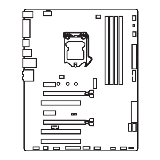
Overview of Components DIMM1 DIMM2 JPWR2 DIMM3 SYSFAN1 CPUFAN1 DIMM4 CPUFAN2 EZ Debug LED SYSFAN3 JPWR1 JUSB2 PCI_E1 M2_1 PCI_E2 PCI1 JCI1 SE1_21-SE2_56 PCI_E3 JBAT1 PCI_E4 SATA4 JTBT1* PCI2 SATA3 PCI3 JAUD1 JFP2 JFP1 SYSFAN2 JUSB1 JCOM1 JTPM1 SLOW_1 (optional) JLPT1 *JTBT1 is used to connect a specific card. -
Page 25: Component Contents
Component Contents Port Name Port Type Page CPUFAN1~2, SYSFAN1~3 Fan Connectors CPU Socket LGA1151 CPU Socket DIMM1~4 DIMM Slots EZ Debug LED Debug LED indicators JAUD1 Front Audio Connector JBAT1 Clear CMOS (Reset BIOS) Jumper JCI1 Chassis Intrusion Connector JCOM1 Serial Port Connector JFP1, JFP2 Front Panel Connectors... -
Page 26: Cpu Socket
Always unplug the power cord from the power outlet before installing or removing the CPU. Please retain the CPU protective cap after installing the processor. MSI will deal with Return Merchandise Authorization (RMA) requests if only the motherboard comes with the protective cap on the CPU socket. -
Page 27: Dimm Slots
DIMM Slots DIMM1 DIMM3 Channel A Channel B DIMM2 DIMM4 Memory module installation recommendation DIMM4 DIMM4 DIMM3 DIMM2 DIMM2 DIMM2 DIMM1 Important Always insert memory modules in the DIMM2 slot first. Due to chipset resource usage, the available capacity of memory will be a little less than the amount of installed. -
Page 28: Pci_E1~4, Pci1~3: Pcie And Pci Expansion Slots
PCI_E1~4, PCI1~3: PCIe and PCI Expansion Slots PCI_E1: PCIe 3.0 x1 slot PCI_E2: PCIe 3.0 x16 slot PCI1: PCI slot PCI_E3: PCIe 3.0 x1 slot PCI_E4: PCIe 3.0 x4 slot PCI2: PCI slot PCI3: PCI slot Multiple graphics cards installation recommendation Important For a single PCIe x16 expansion card installation with optimum performance, using the PCI_E2 slot is recommended. -
Page 29: Sata1~6: Sata 6Gb/S Connectors
SATA1~6: SATA 6Gb/s Connectors These connectors are SATA 6Gb/s interface ports. Each connector can connect to one SATA device. SATA5 SATA1 SATA6 SATA2 SATA4 SATA3 SE1_21-SE2_65: SATAe Connectors These connectors are SATAe (SATA Express) interface ports. Each SATAe connector can be used with a single SATAe device or two legacy SATA devices. SATA6 SATAe2 (optional) -
Page 30: Installing M.2 Module
M2_1: M.2 Slot Important Intel RST only supports PCIe M.2 SSD with UEFI ROM, ® does not support Legacy ROM. Installing M.2 module Remove the screw from the base screw. Remove the base screw. Tighten the base screw into the hole of the distance to the M.2 slot as the length your M.2 module. - Page 31 M.2/ SATA & SATAe combination table Slot Available SATA/ SATAe connectors M2_1 Empty SATA PCIe ✓ ✓ ✓ SATA_EX1 ✓ ✓ ✓ SATA_EX2 (optional) ✓ ─ ✓ SATA1 ✓ ─ ✓ SATA2 ✓ ✓ ─ SATA3 ✓ ✓ ─ SATA4 ✓...
-
Page 32: Jpwr1~2: Power Connectors
JPWR1~2: Power Connectors These connectors allow you to connect an ATX power supply. JPWR2 Ground +12V Ground +12V Ground +12V Ground +12V +3.3V +3.3V +3.3V -12V Ground Ground PS-ON# Ground Ground Ground JPWR1 Ground Ground PWR OK 5VSB +12V +12V +3.3V Ground Important... -
Page 33: Jusb1: Usb 2.0 Connector
JUSB1: USB 2.0 Connector This connector allows you to connect USB 2.0 ports on the front panel. USB0- USB1- USB0+ USB1+ Ground Ground No Pin Important Note that the VCC and Ground pins must be connected correctly to avoid possible damage. -
Page 34: Jtpm1: Tpm Module Connector
JTPM1: TPM Module Connector This connector is for TPM (Trusted Platform Module). Please refer to the TPM security platform manual for more details and usages. LPC Clock 3V Standby power LPC Reset 3.3V Power LPC address & data pin0 Serial IRQ LPC address &... -
Page 35: Cpufan1~2, Sysfan1~3: Fan Connectors
CPUFAN1~2, SYSFAN1~3: Fan Connectors Fan connectors can be classified as PWM (Pulse Width Modulation) Mode and Voltage Mode. PWM Mode fan connectors provide constant 12V output and adjust fan speed with speed control signal. Voltage Mode fan connectors control fan speed by changing voltage. -
Page 36: Jfp1, Jfp2: Front Panel Connectors
JFP1, JFP2: Front Panel Connectors These connectors connect to the switches and LEDs on the front panel. JFP1 HDD LED + Power LED + HDD LED - Power LED - Reset Switch Power Switch Reset Switch Power Switch Reserved No Pin Speaker - Buzzer + JFP2... -
Page 37: Jbat1: Clear Cmos (Reset Bios) Jumper
JBAT1: Clear CMOS (Reset BIOS) Jumper There is CMOS memory onboard that is external powered from a battery located on the motherboard to save system configuration data. If you want to clear the system configuration, set the jumpers to clear the CMOS memory. Keep Data Clear CMOS/ Reset BIOS... -
Page 38: Ez Debug Led: Debug Led Indicators
EZ Debug LED: Debug LED indicators These LEDs indicate the status of the motherboard. VGA - indicates GPU is not detected or fail. DRAM - indicates DRAM is not detected or fail. CPU - indicates CPU is not detected or fail. -
Page 39: Entering Bios Setup
Press Delete key, when the Press DEL key to enter Setup Menu, F11 to enter Boot Menu message appears on the screen during the boot process. Use MSI FAST BOOT application. Click on GO2BIOS button and choose OK. The system will reboot and enter BIOS setup directly. -
Page 40: Resetting Bios
Updating BIOS Updating BIOS with M-FLASH Before updating: Please download the latest BIOS file that matches your motherboard model from MSI website. And then save the BIOS file into the USB flash drive. Updating BIOS: Press Del key to enter the BIOS Setup during POST. - Page 41 EZ Mode At EZ mode, it provides the basic system information and allows you to configure the basic setting. To configure the advanced BIOS settings, please enter the Advanced Mode by pressing the Setup Mode switch or F7 function key. XMP switch Setup Mode switch Screenshot...
- Page 42 GAME BOOST toggle - click on it to toggle the GAME BOOST for OC. Important Please don’ t make any changes in OC menu and don’ t load defaults to keep the optimal performance and system stability after activating the GAME BOOST function. Favorites - press any Favorites tab or the F3 key to enter Favorites menu.
-
Page 43: Advanced Mode
Advanced Mode Press Setup Mode switch or F7 function key can switch between EZ Mode and Advanced Mode in BIOS setup. XMP switch Setup Mode switch Screenshot Favorites Language System information GAME BOOST toggle Boot device priority bar BIOS menu BIOS menu selection selection... -
Page 44: System Status
SETTINGS System Status System Date Sets the system date. Use tab key to switch between date elements. The format is <day> <month> <date> <year>. <day> Day of the week, from Sun to Sat, determined by BIOS. Read-only. <month> The month from Jan. through Dec. <date>... - Page 45 fPEG X - Max Link Speed [Auto] Sets PCI Express protocol of PCIe x16 slots for matching different installed devices. [Auto] This item will be configured automatically by BIOS. [Gen1] Enables PCIe Gen1 support only. [Gen2] Enables PCIe Gen2 support only. [Gen3] Enables PCIe Gen3 support only.
- Page 46 fIpv6 PXE Support [Enabled]) When “Enabled” , the system UEFI network stack will support Ipv6 protocol. This item will appear when “Network Stack” is enabled. [Enabled] Enables the Ipv6 PXE boot support. [Disabled] Disables the Ipv6 PXE boot support. fSATA Mode [AHCI Mode] Sets the operation mode of the onboard SATA controller.
- Page 47 fUSB Controller [Enabled] Enables or disables all USB controller. fXHCI Hand-off [Enabled] Enables or disables XHCI hand-off support for the operating system without XHCI hand-off feature. This item will appear when USB Controller is enabled. fLegacy USB Support [Enabled] Sets Legacy USB function support. [Auto] The system will automatically detect if any USB device is connected and enable the legacy USB support.
- Page 48 Disables this function. fMSI Fast Boot [Disabled] MSI Fast Boot is the fastest way to boot the system. It will disable more devices to speed up system boot time which is faster than the boot time of Fast Boot. [Enabled] Enables the MSI Fast Boot function to speed up booting time.
- Page 49 Boot [Disabled/ windows7, Enabled/ windows 8.1/ 10] Enables or disables the fast boot feature for Windows 8.1/ 10. This item will only be available when MSI Fast Boot is disabled. [Enabled] Enables the Fast Boot configuration to accelerate system boot time.
- Page 50 fDate (of month) Alarm/ Time (hh:mm:ss) Alarm Sets RTC alarm date/ Time. If Resume By RTC Alarm is set to [Enabled], the system will automatically resume (boot up) on a specified date/hour/minute/second in these fields (using the <+> and <-> to select the date & time settings). fResume By PCI/ PCI-E Device [Disabled] Enables or disables the system wake up by PCI/ PCI express devices.
- Page 51 Bootup NumLock State [On] Select the keyboard NumLock state upon bootup. Boot Mode Select [LEGACY+UEFI] Sets the system boot mode from legacy or UEFI architecture depending on OS installation requirement. This item will become un-selectable and will be configured automatically by BIOS when Windows 8.1/ 10 WHQL Support is enabled. [UEFI] Enables UEFI BIOS boot mode support only.
-
Page 52: Save And Exit
Trusted Computing Sets TPM (Trusted Platform Module) function. fSecurity Device Support [Enabled] Enables or disables the TPM function to build the endorsement key for accessing the system. fTPM Device Selection [PTT] Selects TPM device: PTT or dTPM. [PTT] Select it for Intel Platform Trust technology [dTPM] Select it for installed TPM device. - Page 53 Important Overclocking your PC manually is only recommended for advanced users. Overclocking is not guaranteed, and if done improperly, it could void your warranty or severely damage your hardware. If you are unfamiliar with overclocking, we advise you to use GAME BOOST function for easy overclocking.
- Page 54 CPU Ratio Mode [Dynamic Mode]* Selects the CPU Ratio operating mode. This item will appear when you set the CPU ratio manually. [Fixed Mode] Fixes the CPU ratio. [Dynamic Mode] CPU ratio will be changed dynamically according to the CPU loading.
- Page 55 CPU Base Clock Apply Mode [Auto]* Sets the applying mode for adjusted CPU base clock. [Auto] This setting will be configured automatically by BIOS. [Next Boot] CPU will run the adjusted CPU base clock at next boot. [Immediate] CPU runs the adjusted CPU base clock immediately. [During Boot] CPU will run the adjusted CPU base clock during boot.
- Page 56 CPU Core/ GT Voltage Mode [Auto]* Selects the control mode for CPU Core/ GT voltages. [Auto] This setting will be configured automatically by BIOS. [Adaptive Mode] Sets the adaptive voltage automatically for optimizing the system performance. [Override Mode] Allows you to set the voltage manually. [Offset Mode] Allows you to set the offset voltage and select the voltage offset mode.
- Page 57 CPU Features Press <Enter> to enter the sub-menu. fHyper-Threading [Enabled] Intel Hyper-Threading technology treats the multi cores inside the processor as multi logical processors that can execute instructions simultaneously. In this way, the system performance is highly improved. This item appears when the installed CPU supports this technology.
- Page 58 fAdjacent Cache Line Prefetch [Enabled] Enables or disables the CPU hardware prefetcher (MLC Spatial prefetcher). [Enabled] Enables adjacent cache line prefetching for reducing the cache latency time and tuning the performance to the specific application. [Disabled] Enables the requested cache line only. fCPU AES Instructions [Enabled] Enables or disables the CPU AES (Advanced Encryption Standard-New Instructions) support.
- Page 59 fIntel Turbo Boost [Enabled] Enables or disables the Intel Turbo Boost. This item is for Normal mode and ® appears when a CPU that support Turbo Boost is installed. [Enabled] Enables this function to boost CPU performance automatically over specification when system request the highest performance state. [Disabled] Disables this function.
- Page 60 M-FLASH provides the way to update BIOS with a USB flash drive. Please download the latest BIOS file that matches your motherboard model from MSI website, save the BIOS file into your USB flash drive. And then follow the steps below to update BIOS.
-
Page 61: Overclocking Profile
OC PROFILE Overclocking Profile 1/ 2/ 3/ 4/ 5/ 6 Overclocking Profile 1/ 2/ 3/ 4/ 5/ 6 management. Press <Enter> to enter the sub- menu. fSet Name for Overclocking Profile 1/ 2/ 3/ 4/ 5/ 6 Name the current overclocking profile. fSave Overclocking Profile 1/ 2/ 3/ 4/ 5/ 6 Save the current overclocking profile. -
Page 62: Hardware Monitor
HARDWARE MONITOR Current Temperature & Speed information Fan control field Setting Buttons Voltage display Current Temperature & Speed information Shows the current CPU temperature, system temperature and fans' speeds. Fan control field This motherboard provides a fan speed control feature call Smart Fan. Please check the Smart Fan Mode box to enable the Smart Fan. -
Page 63: Software Description
Windows 7. Installing Drivers Start up your computer in Windows 7/ 8.1/ 10. ® Insert MSI Driver Disc into your optical drive. ® The installer will automatically appear and it will find and list all necessary drivers. -
Page 64: Command Center
COMMAND CENTER COMMAND CENTER is an user-friendly software and exclusively developed by MSI, helping users to adjust system settings and monitor status under OS. With the help of COMMAND CENTER, making it possible to achieve easier and efficient monitoring process and adjustments than that under BIOS. In addition, the COMMAND CENTER can be a server for mobile remote control application. - Page 65 CPU Fan CPU Fan control panel provides Smart mode and Manual Mode. You can switch the control mode by clicking the Smart Mode and Manual Mode buttons on the top of the CPU Fan control panel. Manual Mode - allows you to manually control the CPU fan speed by percentage.
- Page 66 GAME BOOST GAME BOOST provides a specified CPU frequency for overclocking the CPU. Option Buttons - Advanced When click the Advanced button, The Voltage, Fan and DRAM icons will appear. Voltage - allows you to adjust advanced voltage values of CPU and chipset. Fan - allows you to control the system fans speed.
- Page 67 Find the IP address on the SoftAP Management Setting area, and enter the IP address on your MSI COMMAND CENTER APP to link your system. ® Press Refresh on the MSI COMMAND CENTER APP to verify that monitoring and ® OC functions are working properly.
-
Page 68: Live Update
LIVE UPDATE 6 LIVE UPDATE 6 is an application for the MSI system to scan and download the latest ® drivers, BIOS and utilities. With LIVE UPDATE 6, you don’ t need to search the drivers on websites, and don’ t need to know the models of motherboard and graphics cards. -
Page 69: Total Installer
Choose Automatic scan, system will automatically scan all the items and search for the latest update files. Or you can choose Manual scan and select the items you wish to scan. Click the Scan button at the bottom. It may take several moments to complete the process. -
Page 70: Gaming App
GAMING APP GAMING APP is an application designed to quickly control your system for improving gaming performance. Setting Button Information Button Display Mode Button CPU Frequency GPU Frequency Gaming Function Full Speed GPU Fan Buttons Control Mode Buttons Setting Button - allows you to run GAMING APP when Windows starts. Information Button - shows the information of this application. - Page 71 Login Keys - provides hotkey login function. ƒ MSI Smart Keys - allows you to define hotkeys for MSI Smart Keys. ƒ Hotkey Manager - allows you to create, edit and delete hotkeys. Current Hotkeys - shows all existing hotkeys.
- Page 72 Important The Caps Lock, Num Lock, Scroll Lock, Window Home, Application and BackSpace keys can not be used as hot-keys. Some key combinations are reserved for use by Microsoft Windows and can not be assigned as a hotkey. Gaming Mouse Control Gaming Mouse Control provides mouse macro function.
- Page 73 M-CLOUD M-CLOUD is an application of MSI network sharing. It allows you to turn your computer into Wi-Fi AP. It can also transfer files between your MSI computers. Soft AP ON/OFF History Server Information Users & Permissions Server Local Directory...
- Page 74 Setting up Soft AP (optional) The Soft AP function is only available for the motherboard with the built-in WiFi module. You can share your network connection to your smartphones, tablets and laptops with the Soft AP function. Important You must have an active network connection and an installed Wi-Fi moudle to enable Soft AP.
-
Page 75: Managing User Accounts
Managing User Accounts This section describes how to create/ remove a user account and configure individual access permissions. Click the Users & Permissions button and the Users & Permissions Management window will pop up. Click Add Account button create a new user account. Fill in user’... - Page 76 RAMDISK RAMDISK creates a virtual RAM drive using the available memory in your computer, the performance of the RAMDISK is faster than an SSD and hard drive. RAMDISK allows you to store any temporary information on it. Furthermore, using the RAMDISK will extend your SSD’...
-
Page 77: Killer Network Manager
In case no icon is shown on the system tray, it is possible to activate Killer Network Manager manually by clicking Start > Programs > MSI > Killer Network Manager. Applications - displays currently using network bandwidth applications. Performance - shows top 5 applications by total traffic, allows you to monitor network bandwidth usage. -
Page 78: Installation And Update
HD Audio Recorder. Installation and Update Nahimic is included in the audio driver. If you need to install it or update it, please use the Driver Disc with your motherboard or download the driver from MSI’ s official website. Audio Tab From this tab, you can access all of Nahimic’... - Page 79 Microphone Tab From this tab, you can access all of Nahimic’ s microphone effects and settings. Listen to your Automatic Calibration Micphone Effects Listen to your MIC - turns the microphone loopback On/Off. Automatic Calibration - dynamically adjusts the Noise Gate threshold and the Noise Reduction level by estimating the noise VS.
-
Page 80: Extreme Tuning Utility
Intel Extreme Tuning Utility ® Intel Extreme Tuning Utility (Intel XTU) is a simple overclocking software for you to ® tune, test and monitor your system. Tuning Controls Views Settings Help System Navigation Table System System Monitors Graphs Views Settings Help Views - toggles to switche between Monitoring and Show All view. -
Page 81: Raid Configuration (Optional)
RAID Configuration (optional) Below are the different types of a RAID. RAID 0 breaks the data into blocks which are written to separate hard drives. Spreading the hard drive I/O load across independent channels greatly improves I/O performance. RAID 1 provides data redundancy by mirroring data between the hard drives and provides enhanced read performance. -
Page 82: Creating Raid Volume
Creating RAID Volume Select option Create RAID Volume and press Enter key. The following screen appears. CREATE VOLUME MENU Name : Volume0 RAID Level : RAID1(Mirror) Disks : Select Disks Strip Size : N / A Capacity : XXX.X GB Sync : N / A Create Volume... -
Page 83: Delete Raid Volume
Delete RAID Volume Here you can delete the RAID volume, but please be noted that all data on RAID drives will be lost. Important If your system currently boots to RAID and you delete the RAID volume in the IRST Option ROM, your system will become unbootable. -
Page 84: Recovery Volume Options
Important You will lose all data on the RAID drives and any internal RAID structures when you perform this operation. Possible reasons to Reset Disks to Non-RAID could include issues such as incompatible RAID configurations or a failed volume or failed disk. Recovery Volume Options Select option Recovery Volume Options from the main menu screen and press Enter to change recovery volume mode. -
Page 85: Failed Hard Drive Member
Reboot to Windows ; the rebuild will occur automatically. ® Failed Hard Drive Member Power off. Replace the failed hard drive with a new one that is of equal or greater capacity. Reboot the system to IRST Option ROM by press Ctrl + I keys during the POST. Select the port of the destination disk for rebuilding, and then press Enter. -
Page 86: Troubleshooting
Troubleshooting Lost BIOS password Before sending the motherboard for RMA repair, try to go over troubleshooting Clear the CMOS, but that will cause guide first to see if your got similar you to lose all customized settings in symptoms as mentioned below. the BIOS.