Advertisement
Table of Contents
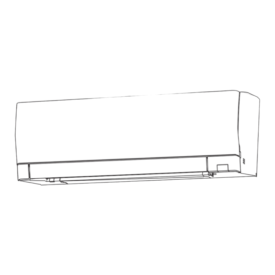
INDOOR UNIT
SERVICE MANUAL
Models
MSZ-AY25VGK -
MSZ-AY35VGK -
MSZ-AY42VGK -
MSZ-AY50VGK -
MSZ-AY25VGKP -
E6
MSZ-AY35VGKP -
E6
MSZ-AY42VGKP -
E6
MSZ-AY50VGKP -
E6
CONTENTS
1. TECHNICAL CHANGES ······························3
2. PART NAMES AND FUNCTIONS ··················4
3. SPECIFICATION ········································5
4. NOISE CRITERIA CURVES ··························6
5. OUTLINES AND DIMENSIONS ·····················7
6. WIRING DIAGRAM ·····································8
7. REFRIGERANT SYSTEM DIAGRAM ··········· 10
8. SERVICE FUNCTIONS ······························ 11
9. MICROPROCESSOR CONTROL ················· 17
10. TROUBLESHOOTING ······························· 25
11. DISASSEMBLY INSTRUCTIONS ················· 41
PARTS CATALOG (OBB930)
No. OBH930
Outdoor unit service manual
MUZ-AY∙VG/VGH Series (OBH931)
MXZ-F∙VF/VFH Series (OBH790)
E6
E6
E6
E6
Advertisement
Table of Contents

Related Manuals for Mitsubishi Electric MSZ-AY25VGKP-E6


Summary of Contents for Mitsubishi Electric MSZ-AY25VGKP-E6
-
Page 1: Table Of Contents
INDOOR UNIT No. OBH930 SERVICE MANUAL Models MSZ-AY25VGK - MSZ-AY25VGKP - MSZ-AY35VGK - MSZ-AY35VGKP - MSZ-AY42VGK - MSZ-AY42VGKP - MSZ-AY50VGK - MSZ-AY50VGKP - Outdoor unit service manual MUZ-AY∙VG/VGH Series (OBH931) MXZ-F∙VF/VFH Series (OBH790) CONTENTS 1. TECHNICAL CHANGES ······························3 2. PART NAMES AND FUNCTIONS ··················4 3. - Page 2 Use the specified refrigerant only Never use any refrigerant other than that specified. Doing so may cause a burst, an explosion, or fire when the unit is being used, serviced, or disposed of. Correct refrigerant is specified in the manuals and on the spec labels provided with our products. We will not be held responsible for mechanical failure, system malfunction, unit breakdown or accidents caused by failure to follow the instructions.
-
Page 3: Technical Changes
TECHNICAL CHANGES These models are compatible with the outdoor units with low standby power control. Connecting these models to the MUZ-AY·VG/VGH series outdoor units enables the low standby power control. These models may be connected to the MUZ-AY·VG/VGH series after once connected to the MXZ series and operated, for example because of relocation. -
Page 4: Part Names And Functions
PART NAMES AND FUNCTIONS MSZ-AY25VGK MSZ-AY35VGK MSZ-AY42VGK MSZ-AY50VGK MSZ-AY25VGKP MSZ-AY35VGKP MSZ-AY42VGKP MSZ-AY50VGKP Air purifying device (VGKP type only) Front panel Air inlet Wi-Fi interface Air fi lter Air cleaning fi lter (V Blocking Filter) Emergency operation switch Spec name plate *1 Horizontal vane *1 The manufacturing year and month are indicated on the... -
Page 5: Specification
SPECIFICATION MSZ-AY25VGK MSZ-AY35VGK MSZ-AY42VGK MSZ-AY50VGK Indoor model MSZ-AY25VGKP MSZ-AY35VGKP MSZ-AY42VGKP MSZ-AY50VGKP Single phase 230 V, 50 Hz Power supply Cooling Power input *1 Heating Cooling 0.18 0.24 Running current *1 Heating 0.26 0.32 RC0J30CV Model Cooling 0.18 0.24 Current *1 Heating 0.26 0.32... -
Page 6: Noise Criteria Curves
NOISE CRITERIA CURVES MSZ-AY25VGK MSZ-AY35VGK MSZ-AY25VGKP MSZ-AY35VGKP FAN SPEED FUNCTION SPL(dB(A)) LINE FAN SPEED FUNCTION SPL(dB(A)) LINE COOLING COOLING Super High Super High HEATING HEATING NC-70 NC-70 NC-60 NC-60 NC-50 NC-50 NC-40 NC-40 NC-30 NC-30 NC-20 NC-20 1000 2000 4000 8000 1000 2000... -
Page 7: Outlines And Dimensions
OUTLINES AND DIMENSIONS Unit: mm MSZ-AY25VGK MSZ-AY35VGK MSZ-AY42VGK MSZ-AY50VGK MSZ-AY25VGKP MSZ-AY35VGKP MSZ-AY42VGKP MSZ-AY50VGKP Insulation ø37 O.D Liquid line ø6.35 - 0.39m (Flared connection ø6.35) Gas line ø9.52 - 0.34m (Flared connection ø9.52) Drain hose Insulation ø29 Connected part ø16 O.D OBH930... -
Page 8: Wiring Diagram
WIRING DIAGRAM MSZ-AY25VGK MSZ-AY35VGK MSZ-AY42VGK MSZ-AY50VGK OBH930... - Page 9 MSZ-AY25VGKP MSZ-AY35VGKP MSZ-AY42VGKP MSZ-AY50VGKP OBH930...
-
Page 10: Refrigerant System Diagram
REFRIGERANT SYSTEM DIAGRAM Unit: mm MSZ-AY25VGK MSZ-AY35VGK MSZ-AY25VGKP MSZ-AY35VGKP Refrigerant pipe ø9.52 (with heat insulator) Indoor coil Indoor thermistor heat RT12 (main) exchanger Flared connection Indoor coil thermistor RT13 (sub) Room temperature thermistor RT11 Flared connection Refrigerant pipe ø6.35 (with heat insulator) Refrigerant flow in cooling Refrigerant flow in heating MSZ-AY42VGK MSZ-AY50VGK... -
Page 11: Service Functions
SERVICE FUNCTIONS MSZ-AY25VGK MSZ-AY35VGK MSZ-AY42VGK MSZ-AY50VGK MSZ-AY25VGKP MSZ-AY35VGKP MSZ-AY42VGKP MSZ-AY50VGKP 8-1. TIMER SHORT MODE For service, the following set time can be shortened by bridging the timer short mode point on the electronic control P.C. board. (Refer to 10-7.) • The set time for the ON/OFF timer can be reduced to 1 second for each minute. •... - Page 12 8-4. Wi-Fi INTERFACE SETTING UP 3-1. Setting up in WPS-PUSH mode This Wi-Fi interface, communicates the status information and controls the commands from the MELCloud by connecting to the WPS-Push mode To enter the mode indoor unit. Front panel (1) Hold down the Temperature 5 seconds.
- Page 13 3-2. Setting up in Access Point mode 3-2.3. Register the information of the router on the air conditioner. Complete the setting up in the Access Point mode within 10 minutes. In the displayed window, select Dynamic in Access Point mode DHCP (*1) and enter the information of router, To enter the mode then tap the Submit button.
- Page 14 • This Wi-Fi interface should not be installed and the router does not exceed the limit. connected to any Mitsubishi Electric system which is • Make sure that DHCP is enabled, or check IP to provide application critical cooling or heating.
- Page 15 8-5. CHANGING THE CORRECTION VALUE OF THE ROOM TEMPERATURE (THE INLET TEMPERATURE) The correction value of the room temperature can be adjusted in the range of 2 to 5 °C with the remote controller. Normally, the temperature at the room temperature sensor might become higher than that around feet because warm air tends to accumulate around an indoor unit during heating operation.
- Page 16 2. Writing the correction value of the room temperature on the wiring diagram After setting the correction value of the room temperature (the inlet air temperature), follow 11. DISASSEMBLY INSTRUCTIONS to disassemble the indoor unit, and then write the correction value (any of 3, 4, or 5) on the wiring dia- gram with a ballpoint pen, etc.
-
Page 17: Microprocessor Control
MICROPROCESSOR CONTROL MSZ-AY25VGK MSZ-AY35VGK MSZ-AY42VGK MSZ-AY50VGK MSZ-AY25VGKP MSZ-AY35VGKP MSZ-AY42VGKP MSZ-AY50VGKP WIRELESS REMOTE CONTROLLER Signal transmitting section Distance of signal : About 6 m Beep(s) is (are) heard from the indoor unit when the signal is received. Battery replacement indicator FAN speed control button Operation display section Operation select button WIDE VANE button... - Page 18 2. Low outside temperature operation When the outside temperature is lower, low outside temperature operation starts, and the outdoor fan slows or stops. 3. Indoor fan speed control When the thermostat turns OFF, the indoor fan operates very Low to reduce power consumption. When the room temperature rises and the thermostat is ON, the indoor fan operates according to the settings on the remote controller.
- Page 19 NOTE 2 FOR MULTI SYSTEM AIR CONDITIONER OUTDOOR UNIT: MXZ series Multi system air conditioner can connect 2 or more indoor units with 1 outdoor unit. • When you try to operate 2 or more indoor units with 1 outdoor unit simultaneously, one for the cooling and the others for heating, the operation mode of the indoor unit that operates first is selected.
- Page 20 (9) ECONO COOL ( ) operation (ECONOmical operation) When ECONO COOL button is pressed in COOL mode, set temperature is automatically set 2°C higher by the microprocessor. (However, the temperature on the LCD screen on the remote controller is not changed.) Also the horizontal vane swings in various cycle.
- Page 21 PROGRAM TIMER • OFF timer and ON timer can be used in combination. The set time that is reached first will operate first. • “ ” and “ ” display shows the order of OFF timer and ON timer operation. (Example 1) The current time is 8:00 PM.
- Page 22 (3) Press , and buttons to set ON/OFF, time, and temperature. E.g. : [ON], [6:00] and [24°C] are selected. Pressing selects ON/OFF timer. Pressing Pressing adjusts the time. adjusts the Pressing temperature. deletes timer setting. * Hold down the button to change the time quickly. * The temperature can be set between 16°C and 31°C at cool operation.
- Page 23 9-10. i-save ( ) OPERATION 1. How to set i-save operation (1) Press OFF/ON (stop/operate) button. (2) Select COOL, HEAT or ECONO COOL mode. (3) Press i-save button. (4) Set the temperature, fan speed, and airflow direction for i-save operation. NOTE: •...
- Page 24 9-14. EMERGENCY/TEST OPERATION In the case of test run operation or the emergency operation, use the emergency operation switch on the right side of the indoor unit. The emergency operation is available when the remote controller is missing or has failed, or the batteries in the remote controller are running down.
-
Page 25: Troubleshooting
TROUBLESHOOTING MSZ-AY25VGK MSZ-AY35VGK MSZ-AY42VGK MSZ-AY50VGK MSZ-AY25VGKP MSZ-AY35VGKP MSZ-AY42VGKP MSZ-AY50VGKP 10-1. CAUTIONS ON TROUBLESHOOTING 1. Before troubleshooting, check the following 1) Check the power supply voltage. 2) Check the indoor/outdoor connecting wire for miswiring. 2. Take care of the following during servicing 1) Before servicing the air conditioner, be sure to turn OFF the main unit first with the remote controller, and after confirm- ing the horizontal vane is closed, turn OFF the breaker and/or disconnect the power plug. - Page 26 10-2. FAILURE MODE RECALL FUNCTION Outline of the function This air conditioner can memorize the abnormal condition which has occurred once. Even though LED indication listed on the troubleshooting check table (10-4.) disappears, the memorized failure details can be recalled. 1.
- Page 27 2. Flow chart of AIR PURIFYING power failure mode recall function (MSZ-AY•VGKP) Operational procedure The air purifying device might be abnormal. Check if the air purifying device is abnormal according to the following procedures. Make sure that the remote controller is set to the failure mode recall function. With the remote controller headed towards the indoor unit, press TEMP *1.
- Page 28 4. Table of indoor unit failure mode recall function NOTE: Blinking patterns of this mode differ from the ones of TROUBLESHOOTING CHECK TABLE (10-4.). The upper lamp of Abnormal point OPERATION Condition Remedy (Failure mode) INDICATOR lamp Not lit Normal —...
- Page 29 10-3. INSTRUCTION OF TROUBLESHOOTING 1. Check of the unit. *1 “Test Run operation” means the *2 There is possibility that diesel explosion may occur due to the air mixed in operation within 30 minutes after the refrigerant circuit. First, ensure that there are no leakage points on the valves, flare connec- the emergency operation switch tions, etc.
- Page 30 2. Check of Wi-Fi interface Follow the procedure below if the air conditioner cannot be monitored or controlled with a device such as a smartphone. Did the LED indication blink 10 times after you There is a problem in a communication between the air con- selected the setting of the Wi-Fi interface and the ditioner and the Wi-Fi interface.
- Page 31 10-4. TROUBLESHOOTING CHECK TABLE Before taking measures, make sure that the symptom reappears for accurate troubleshooting. When the indoor unit has started operation and detected an abnormality of the following condition (the first detection after the power ON), the indoor fan motor turns OFF and OPERATION INDICATOR lamp blinks. OPERATION INDICATOR Blinking Not lit...
- Page 32 OPERATION INDICATOR Blinking Not lit Abnormal Operation indicator lamp Symptom Condition Remedy point Upper lamp lights and lower lamp blinks. The operation mode of the each indoor unit is MXZ type Outdoor unit differently set to COOL (includes DRY) and •...
- Page 33 10-6. TROUBLESHOOTING FLOW A Check of indoor fan motor The indoor fan motor error has occurred, and the indoor fan does not operate. Turn OFF the power supply. Pay enough attention to the high voltage on the fan motor connector CN211. Turn ON the power supply, wait 5 seconds or more, and then press the emergency operation switch.
- Page 34 B Check of remote controller and indoor electronic control P.C. board *Check if the remote controller is exclusive for this air conditioner. Press OFF/ON (stop/operate) button on *1 Look at the image of the signal transmitting section of the remote controller. the remote controller through the monitor of a digital camera or a camera phone.
- Page 35 C Check of indoor P.C. board and indoor fan motor Turn OFF the power supply. Remove the indoor fan motor connector Measure the resistance between CN211 and the vane motor connector Short circuit: CN151 from the indoor electronic control CN211 of the indoor fan motor Replace the indoor fan motor.
- Page 36 D How to check miswiring and serial signal error MUZ Type Turn the main power supply OFF. Is there rated voltage in the power supply? Check the power supply. Check for incorrect indoor-outdoor connecting wiring. Was the indoor unit ever connected to the Multi (MXZ) series and operated (turned on)? The connection information to the Multi series is stored in...
- Page 37 MXZ Type Turn OFF the power supply. LED indication for communication status Communication status is indicated Is there rated voltage in by the LED. Check the power the power supply? supply. Unit status Blinking: normal communication Lit: abnormal communication or not connected Turn ON the power supply.
- Page 38 E Check of AIR PURIFYING power After performing the check, make sure to release the failure mode recall function. High voltage (approximately 5.8kV) is generated during AIR PURIFYING power operation. Turn ON the power supply. Pay careful attention and never touch the air purifying device and the high-voltage lead part.
- Page 39 F Electromagnetic noise enters into TV sets or radios Is the unit earthed? Earth the unit. Is the distance between the antennas Extend the distance between the antennas and and the indoor unit within 3 m, or is the the indoor unit, and/or the antennas and the out- distance between the antennas and the door unit.
- Page 40 10-7. TEST POINT DIAGRAM AND VOLTAGE Indoor terminal P.C. board, Indoor electronic control P.C. board, Receiver P.C. board, Display P.C. board, Switch/buzzer P.C. board MSZ-AY25VGK MSZ-AY35VGK MSZ-AY42VGK MSZ-AY50VGK MSZ-AY25VGKP MSZ-AY35VGKP MSZ-AY42VGKP MSZ-AY50VGKP Terminal P.C.Board To disable “Auto restart function” cut the Jumper wire to JR77. Fuse (Refer to 8-3.) (F11)
-
Page 41: Disassembly Instructions
DISASSEMBLY INSTRUCTIONS <Detaching method of the terminal with locking mechanism> The terminal which has the locking mechanism can be detached as shown below. There are 2 types of the terminal with locking mechanism. The terminal without locking mechanism can be detached by pulling it out. Check the shape of the terminal before detaching. - Page 42 PHOTOS/FIGURES OPERATING PROCEDURE Removing the panel (R) (Photos 1, 2, Figure 1) to 2 (1) Remove the front panel and the horizontal vanes (U) Screw of the Screws of the (L). panel (L) Panel (F) panel (R) (2) Remove the screw cap on the panel (R), and the screw.
- Page 43 PHOTOS/FIGURES OPERATING PROCEDURE 2. Removing the Wi-Fi interface (Photos 3, 5) Photo 3 (1) Remove the front panel and the horizontal vanes (U) Wi-Fi interface (L). Screw of the (2) Remove the panels (R) (L) (U). electrical cover (3) Remove the screw of the V.A. clamp and remove the V.A.
- Page 44 PHOTOS/FIGURES OPERATING PROCEDURE 3. Removing the indoor electrical box and the air Photo 4 purifying device (Photos 3, 4, 5, 6) Lead wire of the indoor coil thermistor (1) Remove the front panel and the horizontal vanes (U) and air purifying device (MSZ-AY·VGKP) (L).
- Page 45 PHOTOS/FIGURES OPERATING PROCEDURE 5. Removing the nozzle assembly Photo 7 (1) Remove the front panel and the horizontal vanes (U) (L). (2) Remove the panels (R) (L) (U) (F). (3) Remove the indoor/outdoor connecting wire (Refer to section 3). (4) Remove the electrical cover (Refer to section 3). (5) Disconnect the following connector: <Indoor electronic control P.C.
- Page 46 PHOTOS/FIGURES OPERATING PROCEDURE 7. Removing the line flow fan, the indoor fan motor Photo 10 assembly, the indoor coil thermistor (Photo 10, Heat exchanger 11, 12) (1) Remove the front panel, the horizontal vanes (U) (L), the panels (R) (L) (F) (U), the Wi-Fi interface, the elec- trical box, and the nozzle assembly.
- Page 47 Fixing the indoor coil thermistor * There are 2 forms of parts for fixing the indoor coil thermistor. When fixing the indoor coil thermistor to the clip-shape/holder-shape part, the Clip shape Holder shape lead wire should point down. About the same length Position and procedure for mounting the clip-shape part 1.
- Page 48 HEAD OFFICE: TOKYO BUILDING, 2-7-3, MARUNOUCHI, CHIYODA-KU, TOKYO 100-8310, JAPAN © Copyright 2022 MITSUBISHI ELECTRIC CORPORATION Published: Nov. 2022. No. OBH930 Made in Japan Specifications are subject to change without notice.