Advertisement
Quick Links
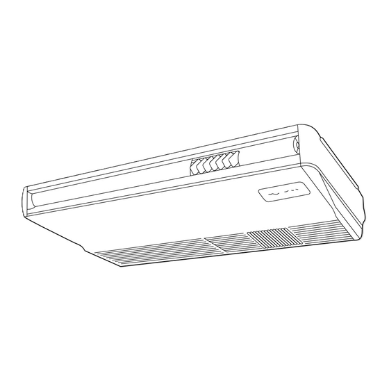
SPLIT-TYPE, COOLING AIR CONDITIONERS
TECHNICAL & SERVICE MANUAL
Series PC
Indoor unit
[Model names]
PC-2GJA
PC-2.5GJA
PC-3GJA
PC-4GJSA
PC-5GJSA
PC-6GJSA
INDOOR UNIT
Revision:
PC-5GJSA
,PC-6GJSA
1
1
.
are added
The first edition has been par-
tially modified.
Please destroy OC134.
Ceiling Suspended
[Service Ref.]
PC-2GJA
1997
PC-2.5GJA
PC-3GJA
PC-4GJSA
PC-5GJSA
1998
PC-6GJSA
TIMER
TEMP
TIMER/TEMP.
12
29
11
28
10
27
9
26
8
25
UP
7
24
6
23
DOWN
5
22
4
21
3
20
2
19
1
18
REMOTE CONTROLLER
1
1
1
1
1
CONTENTS
1. FEATURES ···········································2
2. PART NAMES AND FUNCTIONS ········4
3. SPECIFICATIONS·································6
4. DATA ·····················································9
5. OUTLINES AND DIMENSIONS··········12
6. WIRING DIAGRAM·····························17
7. REFRIGERANT SYSTEM DIAGRAM ······18
8. OPERATION FLOW-CHART ··············20
9. MICROPROCESSOR CONTROL·······23
10. TROUBLE SHOOTING ·······················29
11. DISASSEMBLY PROCEDURE ···········30
POWER
ON/OFF
12. PARTS LIST········································35
COOL
MODE
DRY
SELECT
FAN
13. OPTIONAL PARTS ·····························46
HIGH
FAN
SPEED
LOW
ON
LOUVER
AUTO
STOP
TIMER
MODE
START
The Slim Line.
MITSUBISHI ELECTRIC
From Mitsubishi Electric.
REVISED EDITION-A
This manual does not cover the
following outdoor units.
serving them, please refer to the
service
No.OC127(REVISED EDITION-A) .
[Service Ref.]
PU-2VJA
PU-5YJSA
2
1
PU-2NJA
PU-5TJSA
1
PU-2.5VJA
PU-6YJSA
2
PU-2.5NJA
PU-6TJSA
1
PU-3NJA
1
PU-3YJA
3
PU-3VJA
2
PU-4TJSA
2
PU-4VLJSA
2
PU-4YJSA
3
No. OC134
When
manual
Advertisement

Related Manuals for Mitsubishi Electric Mr.SLIM PC-2GJA


Summary of Contents for Mitsubishi Electric Mr.SLIM PC-2GJA
- Page 1 SELECT 13. OPTIONAL PARTS ·····························46 HIGH SPEED DOWN LOUVER Revision: AUTO STOP TIMER MODE START PC-5GJSA ,PC-6GJSA The Slim Line. MITSUBISHI ELECTRIC are added From Mitsubishi Electric. The first edition has been par- REMOTE CONTROLLER tially modified. Please destroy OC134.
- Page 2 TEMP TIMER/TEMP. POWER ON/OFF COOL MODE SELECT HIGH SPEED DOWN LOUVER AUTO STOP TIMER MODE START MITSUBISHI ELECTRIC Indoor unit Remote controller Cooling Capacity (50 / 60Hz) Service Ref. Btu/h PC-2GJA 5,600/5,400 19,100/18,400 PC-2.5GJA 6,500/7,000 22,200/23,900 PC-3GJA 7,200/7,800 24,600/26,600 PC-4GJSA...
- Page 3 1. AIR OUTLET New PC series models have 1 air outlet (auto vane switching of horizontal air flow / down flow by switched by auto vane) instead of 2 (horizontal, and down flows). Protruding portion A Unifies the air speed 2.
- Page 4 6. QUITENESS ; 43dB : PC-3GJA (HIGH NOTCH) Quiteness of the New PC series product is significant. It is because we have adapted the new shape air outlet and changed the air coures. Auto vane Swing 7. EASY MAINTENANCE ; NO MAINTENANCE NECESSARY FOR 2500 HOURS The new long-life air filter can be used continuously 2500 hours without maintenance (at general office situation).
- Page 5 MODE START remaining number of hours light. effect. Room Temperature display Swing Louver Button Lamps display temperatue set- MITSUBISHI ELECTRIC Used to automatically ings and actual room tempe- disperse airflow vertically. ratues. Air is blown in one Temperatue settings. direction when louver is Green lamps light.
- Page 6 SPECIFICATIONS 1. STANDARD SPECIFICATIONS Service Ref. PC-2GJA PC-2.5GJA PC-3GJA PC-4GJSA Item 5,600 6,500 7,200 9,800 50Hz Btu/h 19,100 22,200 24,600 33,400 Cooling capacity w1 5,400 7,000 7,800 10,800 60Hz Btu/h 18,400 23,900 26,600 36,800 4,300 6,200 6,500 9,300 Cooling capacity w4 60Hz Btu/h 14,700...
- Page 7 Service Ref. PC-5GJSA PC-6GJSA Item 12,400 14,600 50Hz Btu/h 42,300 49,800 Cooling capacity w1 13,500 15,200 60Hz Btu/h 46,100 51,900 11,600 13,400 Cooling capacity w4 60Hz Btu/h 39,600 45,700 Total input (50/60Hz) w2 4.76/5.89 5.31/6.41 PC-5GJSA PC-6GJSA Service Ref. Munsell 0.70Y 8.59/0.97 External finish Fan motor output 0.15...
- Page 8 3. ELECTRICAL SPECIFICATIONS Rating conditions — JIS B8616 Indoor : 27°C (80°F) D.B., 19°C (66°F) W.B. Outdoor : 35°C (95°F) D.B., 24°C(75°F) W.B. Serises PC Indoor unit (Single phase) Power supply (1 Phase) V : 220V , 50Hz Service Ref. PC-2GJA PC-2.5GJA PC-3GJA...
- Page 9 DATA 1. PERFORMANCE DATA Cooling capacity 50Hz PC-2GJA PC-2.5GJA PC-3GJA PC-4GJSA PC-5GJSA PC-6GJSA Service Ref. T.C. C.F. T.C. C.F. T.C. C.F. T.C. C.F. T.C. C.F. T.C. C.F. Temperature Outdoor D.B. Indoor W.B. (T.I.) (T.I.) (T.I.) (T.I.) (T.I.) (T.I.) 16°C ( 60.8°F ) 0.81 0.81 0.81...
- Page 10 Cooling capacity 60Hz Service Ref. PC-2GJA PC-2.5GJA PC-3GJA PC-4GJSA PC-5GJSA PC-6GJSA Temperature T.C. C.F. T.C. C.F. T.C. C.F. T.C. C.F. T.C. C.F. T.C. C.F. (T.I.) (T.I.) (T.I.) (T.I.) (T.I.) (T.I.) Outdoor D.B. Indoor W.B. ( 60.8°F ) 16°C 0.81 0.81 0.81 10.8 0.81...
- Page 11 2. STANDARD OPERATION DATA PC-4GJSA PC-5GJSA PC-6GJSA Service Ref. PC-2GJA PC-2.5GJA PC-3GJA Cooling Cooling Cooling Cooling Cooling Cooling Cooling Cooling Cooling Cooling Cooling Cooling MODE Capacity 5,600 4,300 6,500 6,200 7,200 6,500 9,800 9,300 12,400 11,600 14,600 13,400 Input 2.54 3.12 2.58 3.60...
- Page 12 OUTLINES AND DIMENSIONS 1. INDOOR UNIT PC-2GJA...
- Page 13 PC-2.5GJA PC-3GJA...
- Page 14 PC-4GJSA...
- Page 15 PC-5GJSA PC-6GJSA...
- Page 16 SELECT HIGH SPEED DOWN LOUVER AUTO STOP TIMER MODE START MITSUBISHI ELECTRIC 108(4-1/4) Fixing hole 117(4-5/8) Remote controller cable installation For exposed remote controller cable installation For recessed remote controller cable installation Exposed remote controller cable Remote controller cable Conduit tube...
- Page 17 WIRING DIAGRAM PC-2GJA / PC-2.5GJA / PC-3GJA / PC-4GJSA / PC-5GJSA / PC-6GJSA SYMBOL NAME SYMBOL NAME SYMBOL NAME SYMBOL NAME FAN MOTOR CAPACITOR LD1<R.B> RUN INDICATOR LED SWC<I.B> OPTION SWITCH INDOOR / OUTDOOR CONNECT- CN120<I.B> REMOTE CONTROLLER TRANS- LD3<R.B> COOLING INDICATOR LED SW1<I.B>...
- Page 18 REFRIGERANT SYSTEM DIAGRAM PC-2GJA / PU-2NJA , PU-2VJA Refrigerant pipe 15.88 (5/8) (With insulator) option Flexible tube Low pressure Check switch plug High Ball Charge pressure valve plug switch Outdoor heat exchanger Flared connection Indoor heat exchanger Strainer Accumulator Flared Distributor connection Compressor...
- Page 19 PC-5GJSA , 6GJSA / PU-5YJSA, PU-5TJSA PU-6YJSA, PU-6TJSA INDOOR UNIT OUTDOOR UNIT Refrigerant pipe 19.05 (3/4F) Thermal (With insulator) option switch Check plug Flexible tube Outdoor heat Charge exchanger plug High Ball pressure valve switch Flared connection Indoor heat exchanger Flared Accumulator Distributor...
- Page 20 OPERATION FLOW-CHART Models : PC-GJA 1. Main operation Start POWER SUPPLY Live <w1> TIMER MODE button ON During <w2> operation ON/OFF button ON Protection device AUTO STOP lamp ON AUTO START lamp ON Self hold reset Auto start timer Auto stop timer 1 12Hr up/ press 1 12Hr up/...
- Page 21 COOLING OPERATION COOL operation Initial COOLING Vane initial setting Fan speed Downward discharge 1 hour Vane horizontal Vane setting notch airflow Compressor thermostat Allowance cancel 3-minute time delay 6-minute Allowance time delay period 6 minute 3-minute time delay compressor operation Allowance set Coil frost protection Coil frost...
- Page 22 DRY OPERATION operation Initial dry operation Vane Vane initial setting setting notch Room tempereature is 18°C or lower During compressor ON 3-minute 3-minute compressor time delay operation Compressor & Compressor & thermostat thermostat ON 10-minute Compressor ON compressor time completes Compressor ON 10-minute compressor OFF timer start...
- Page 23 Test run switching. LOUVER AUTO STOP TIMER MODE START MITSUBISHI ELECTRIC Indoor unit Polar, twelve (12) - core cable Maximum length 50m (164ft) INDOOR CONTROLLER BOARD INPUT from indoor unit Room temperature thermistor. Receives orders from remote controller and temperature data from Indoor coil thermistor.
- Page 24 TIMER MODE flashing lamp shows the room temperature. START When the room temperature is equal to the set tempera- MITSUBISHI ELECTRIC ture, the lamp keeps lighting, 0.5 seconds brightly and 0.5 seconds faintly. <COOL operation time chart> Operation starts by...
- Page 25 3. The lighting lamp shows the set temperature, and the flashing lamp shows the START room temperature. MITSUBISHI ELECTRIC When the room temperature is equal to the set temperature, the lamp keeps lighting, 0.5 seconds brightly and 0.5 seconds faintly.
- Page 26 STOP TIMER MODE START TIMER MODE button. To cancel the AUTO STOP timer and stop operation, press the MITSUBISHI ELECTRIC POWER ON/OFF button. <How to operate AUTO START timer> 1 While POWER lamp is OFF, press TIMER MODE button. AUTO TIMER lamps turn ON.
- Page 27 2-5 Test run The unit starts the test run by pressing both the UP and DOWN buttons simultaneously for more than two seconds during TIMER lamp ON or the unit OFF. The test run automatically stops in 2 hours. Set temperature is not displayed during test run. To cancel the test run, press the POWER ON/OFF button.
- Page 28 2-8 Function of jumper wire and dipswitch on indoor controller board 1. Jumper wire 1 JR1 ... Jumper wire for the auto vanes. Cut JR01 for the unit WITHOUT auto vanes. 2 JR2 ... Jumper wire for the temperature to start coil frost prevention Cutting JR02 changes the temperature from +1°C to -3°C.
- Page 29 TROUBLESHOOTING 1. self-diagnostic function ! When trouble occurs during operation, the unit stops and enters the self-diagnostic mode, and displays the trouble loca- tion with the timer lamps on the remote controller. All the other lamps are OFF. @ To activate the self-diagnostic function for service, press the UP and DOWN buttons simultaneously for more than two TIMER seconds during operation with lamp ON.
- Page 30 DISASSEMBLY PROCEDURE PC-3GJA OPERATING PROCEDURE PHOTOS&ILLUSTRATIONS 1. Removing the air intake grill Figure 1 (1) Slide the intake grill holding knobs (at two locations) back- ward to open the intake grill. (2) When the intake grill left open, push the stoppers on the rear hinges (at two locations) to pull out the intake grill.
- Page 31 OPERATING PROCEDURE PHOTOS&ILLUSTRATIONS 3. Removing the fan motor Photo 2 (1) Remove the intake grill. Motor gurd (2) Disconnect the fan motor connector. Screws (3) Unscrew screws for removing the motor guard. Motor (4) Unscrew screws for removing the fan guard. (5) Remove the screw for removing the motor support at both Set screws left and right side.
- Page 32 OPERATING PROCEDURE PHOTOS&ILLUSTRATIONS 6. Removing the vane motor Photo 4 (1) Remove the air intake. Screw (2) Remove the left side panel. Relay connector of (3) Remove the relay connector of vane motor. the vane motor (4) Remove the electrical box. (5) Remove the screws of vane motor, then remove vane motor.
- Page 33 OPERATING PROCEDURE PHOTOS&ILLUSTRATIONS 9. Removing the drain pan Photo 8 (1) Remove the air intake grill. (2) Remove the beam. (3) Remove the side panel (right and left). (4) Remove the under panel. Remove the screws of the right and left side drain pan. (5) Remove the insiation in center of the drain pan, and after removing the screw, remove the drain pan.
- Page 34 OPERATING PROCEDURE PHOTOS&ILLUSTRATIONS 12. Removing the heat exchanger Photo 11 (1) Remove the air intake grill. (2) Remove the beam. (3) Remove the side panel. (right and left) (4) Disconnect the relay connector. (5) Remove the under panel. (6) Remove the drain pan. Pipe (7) Unscrew the screw of the pipe cover, and remove the pipe support...
- Page 35 PARTS LIST FAN PARTS PC-2GJA PC-2GJA Part numbers that are circled not shown in the figure. Q'ty / set Price Wiring Recom- Remarks PC-2 Part No. Part Name Specification Diagram mended Unit Amount (Drawing No.) Symbol Q'ty GJA, GJA FAN MOTOR D09B4P54MS T7W 23J 762 MOTOR LEG...
- Page 36 FAN PARTS PC-2.5GJA, PC-2.5GJA PC-3GJA, PC-3GJA 4 •14 Part numbers that are circled not shown in the figure. Q'ty / set Price Wiring Recom- Remarks PC-2.5 PC-3 Part No. Part Name Specification Diagram mended Unit (Drawing No.) Amount Symbol Q'ty GJA,GJA GJA,GJA FAN MOTOR...
- Page 37 FAN PARTS PC-4GJSA PC-4GJSA 4 •14 Q'ty / set Price Wiring Recom- Remarks PC-4 Part No. Part Name Specification Diagram mended Unit (Drawing No.) Amount Symbol Q'ty GJSA, GJSA FAN MOTOR D10B4P90MS T7W 39J 762 FAN JOINT R01 29J 116 SHAFT R01 29J 100 SLEEVE BEARING...
- Page 38 FAN PARTS PC-5GJSA,PC-6GJSA PC-5GJSA ,PC-6GJSA 4·15 Q'ty / set Price Wiring Recom- Remarks PC-5 PC-6 Part No. Part Name Specification Diagram mended Unit (Drawing No.) Amount Symbol Q'ty GJSA, GJSA, GJSA GJSA T7W 43J 762 FAN MOTOR D10B4P150MS R01 29J 116 FAN JOINT R01 29J 100 SHAFT...
- Page 39 ELECTRICAL PARTS PC-2GJA, PC-2GJA PC-2.5GJA, PC-2.5GJA PC-3GJA, PC-3GJA PC-4GJSA, PC-4GJSA PC-5GJSA, PC-5GJSA PC-6GJSA, PC-6GJSA Q'ty / set Price Wiring Recom- Remarks Specification PC-2 PC-2.5/3 PC-4 PC-5/6 Part No. Part Name Diagram mended Unit (Drawing No.) Amount Symbol Q'ty GJSA GJSA GJSA GJSA CONTROLLER BOARD...
- Page 40 STRUCTURAL PARTS PC-2GJA PC-2GJA 19 13 15...
- Page 41 Part numbers that are circled not shown in the figure. Q'ty / set Price Wiring Recom- Remarks Part No. Part Name Specification PC-2 Diagram mended Unit (Drawing No.) Amount Symbol Q'ty GJA, GJA RIGHT SIDE PANEL R01 17J 661 LEFT SIDE PANEL R01 17J 662 UNDER PANEL R01 17J 669...
- Page 42 STRUCTURAL PARTS PC-2.5GJA / PC-3GJA PC-4GJSA PC-2.5GJA / PC-3GJA PC-4GJSA...
- Page 43 Part numbers that are circled not shown in the figure. Q'ty / set Price Wiring Recom- Remarks Part No. Part Name Specification PC-2.5/3 PC-4 Diagram mended Unit (Drawing No.) Amount Symbol Q'ty GJA,GJA GJSA,GJSA RIGHT SIDE PANEL R01 17J 661 RIGHT SIDE PANEL R01 35J 661 LEFT SIDE PANEL...
- Page 44 STRUCTURAL PARTS PC-5GJSA/PC-6GJSA PC-5GJSA /PC-6GJSA...
- Page 45 Part numbers that are circled not shown in the figure. Q'ty / set Price Wiring Recom- Remarks PC-5/6 Part No. Part Name Specification Diagram mended Unit Amount (Drawing No.) Symbol Q'ty GJSA,GJSA RIGHT SIDE PANEL R01 35J 661 LEFT SIDE PANEL R01 35J 662 UNDER PANEL R01 41J 669...
- Page 46 OPTIONAL PARTS 1. REFRIGERANT PIPES Service Ref. : PC-2GJA / PC-2.5GJA / PC-3GJA Part No. PAC-05FFS-E PAC-07FFS-E PAC-10FFS-E PAC-15FFS-E Pipe length Pipe size O.D. Liquid:{9.52 Gas:{15.88 Connection method Indoor unit:Flared Outdoor unit:Flared Service Ref. : PC-4GJSA /PC-5GJSA /PC-6GJSA Part No. PAC-SC51PI-E PAC-SC52PI-E PAC-SC53PI-E...
- Page 47 D U A L C E N T R A L CENTRAL O P E R A T I O N MITSUBISHI ELECTRIC 10 9 8 7 6 5 4 3 2 1 1 1 7 3-2. Names and Functions POWER ON/OFF switch Operation ON/OFF switch.
- Page 48 3-3 Connection method (1) Connections in the power supply cord. 1. Connect the power supply cord to the power supply terminal-block and fix it in-place with a tie-lap. Connect a single phase 200V AV (220, 230, 240V) to is the GND terminal, be sure to ground the earth wire. 2.
- Page 49 4. Set the address number (from SW1-1 to SW1-6) in 10 9 8 7 6 5 4 3 2 1 the dipswitch when a centralized remote controller is being used. The address is the control number of each unit in the Levers No.
- Page 50 5. PROGRAM TIMER ADAPTER This adapter is needed when a program timer(PAC-815PT)or a centralized remote controller(PAC-805RC)is used. Part No. PAC-825AD 5-1 Parts included 1 ADAPTER ·························1P 2 3-core cable···························1P 3 3-core cable···························1P Length : 2m (6' 7") Length : 2m (6' 7") 4 4-core cable···························1P 5 5-core cable···························1P Length : 2m (6' 7")
- Page 51 6.REMOTE INDICATION ADAPTER This adapter is used for remote indication (operation / check). Part No. PAC-559AD XHP-3 <Wiring> GREEN YELLOW Power CN51 supply ORANGE connector (5P) BROWN Electrical insulation is needed. Optional multiple display Wiring at the actual place adapter The maximum distance between indoor board and relay is 10m.
- Page 52 HEAD OFFICE MITSUBISHI DENKI BLDG.MARUNOUCHI TOKYO100 TELEX J24532 CABLE MELCO TOKYO cCopyright 1997 MITSUBISHI ELECTRIC ENGINEERING CO., LTD. New publication, effective Sep. 1997 Issued in Jun. 1997. No. OC134 2420 Specifications subject to change without notice Issued in Sep. 1997. No. OC134 Revised edition-A 2420...