Advertisement
Quick Links
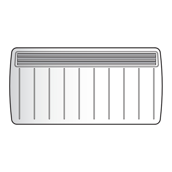
EPX Electronic Panel Convector Heaters
Dimensions
(millimetres)
Model(s)
Watt
EPX 500
0.5kW
EPX 625
0.625kW
EPX 750
0.75kW
EPX 1000
1.0kW
EPX 1250
1.25kW
EPX 1500
1.5kW
EPX 2000
2.0kW
IMPORTANT: THESE INSTRUCTIONS SHOULD BE READ CAREFULLY AND RETAINED FOR FUTURE REFERENCE
Important Safety Advice
When using electrical appliances, basic precautions
should always be followed to reduce the risk of fire,
electrical shock, and injury to persons, including the
following:
IIMPORTANT – The wall brackets supplied with the
appliance must be used.
IMPORTANT – If the heater is installed in a room
containing a bath or shower, it must be so installed that
switches and other controls cannot be touched by a
person using a bath or shower.
Do not use outdoors.
Do not locate the heater immediately below a fixed socket
outlet or connection box.
Do not cover the heater. Do not place material or
garments on the heater, or obstruct the air circulation
around the heater, for instance by curtains or furniture,
as this could cause overheating and a fire risk.
NEVER cover or obstruct in any way the heat outlet slots
at the top of the heater or the air inlet slots in the base of
the heater.
The heater carries the Warning symbol indicating
that it must not be covered.
WARNING – THE SURFACES OF THIS HEATER CAN BE HOT.
Momentary contact with any part of the heater should
not cause injury. However, aged or infirm persons or
young children should not be left unsupervised in the
vicinity of the heater unless a suitable guard is fitted.
This appliance is not intended for use by children or
other persons without assistance or supervision if their
physical, sensory or mental capabilities prevent them
from using it safely. Children should be supervised to
ensure that they do not play with the appliance.
Note that due care and consideration must be taken
when using this heater in series with a thermal control,
a program controller, a timer or any other device that
switches on the heat automatically, since a fire risk
exists when the heater is accidentally covered or
displaced.
If the supply cord is damaged it must be replaced by the
manufacturer or service agent or a similarly qualified
person in order to avoid a hazard.
A
B
450
108
688
108
620
108
620
108
688
108
688
108
860
108
Installation and Operating Instructions
A
150
MIN
Electrical
WARNING – THIS APPLIANCE MUST BE EARTHED
The electrical installation must be carried out by a competent
electrician, and be in strict accordance with the current I.E.E.
regulations for Electrical Equipment in Buildings.
The wires in this mains lead are coloured in accordance
with the following code :
GREEN AND YELLOW :
BLUE :
BROWN :
BLACK :
- see also 'Pilot Wire Connection'.
The heater is fitted with a length of flexible cable type H05VV-
F size 4 x 1.0mm
2
for connection to the fixed wiring of the
premises through a suitable connection box positioned
adjacent to the heater.
The supply circuit to the heater must incorporate a double
pole isolating switch having a contact separation of at least
3mm.
Pilot Wire Connection
The BLACK control wire is designed to carry a signal from
slot in or wall mounted Dimplex programmers. If, however a
programmer is not being used, the pilot wire should be
isolated in accordance with the current IEE Wiring
Regulations.
IMPORTANT - DO NOT connect the BLACK pilot wire to earth.
Care should be taken with the installation of the pilot wire(s)
as when switching to background (set back) they become
energised at 240V although only at a current of less than
100mA. In every case a suitable means of isolation must be
provided for the pilot wire and marked to indicate that two
sources of supply may be present at the heater.
Where pilot wires are installed separately from the heater
final sub-circuit they should be protected, double insulated
and carry their own integral earth continuity conductor.
Supplementary Earth Bonding
Should Equipotential Earth Bonding be required the earthing
conductor in the supply cord is deemed to provide the
supplementary bonding connection (see Regulation 547-
03-05, 16
th
Edition I.E.E. Wiring Regulations).
INDPUKELRG
Issue 0
'x'
150
MIN
430
150
MIN
Fig. 1
EARTH
NEUTRAL
LIVE
PILOT WIRE
B
Advertisement

Related Manuals for Dimplex EPX Series


Summary of Contents for Dimplex EPX Series
- Page 1 The BLACK control wire is designed to carry a signal from that it must not be covered. slot in or wall mounted Dimplex programmers. If, however a programmer is not being used, the pilot wire should be WARNING – THE SURFACES OF THIS HEATER CAN BE HOT.
- Page 2 General Turn on the heater using the ‘ ’ button and move the thermostat slider to the desired position. When the room The EPX Convector is designed for wall mounting on the temperature has reached the desired level, the power to the wall brackets supplied.
- Page 3 Accessory Modules Insert the accessory module into the slot ensuring it is positively located in position - see Fig. 7. Optional accessory modules are available for use with EPX Switch the heater on at the mains supply. range of panel heaters - see separate User Instructions for details on the operation of each accessory module.
- Page 4 Hampshire. SO30 2DF Republic of Ireland Tel. 01 8424833 [c] Glen Dimplex UK Limited All rights reserved. Material contained in this publication may not be reproduced in whole or in part, without prior permission in writing of Glen Dimplex UK Limited.