
Related Manuals for LG LV-B1860RL


Summary of Contents for LG LV-B1860RL
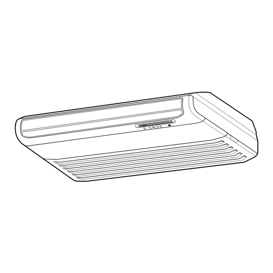
- Page 1 Библиотека СОК Room Air Conditioner (Convertible Type) SERVICE MANUAL MODEL: LV-B1860RL LV-B2460RL (Applied to new Refrigerant R-410A)
-
Page 2: Table Of Contents
Contents Functions ..........................3 Product Specifications (Cooling & Heating).................5 Dimensions ..........................6 Refrigeration Cycle Diagram ....................8 Wiring Diagram........................9 Operation Details ........................10 Display Function ........................18 Self-diagnosis Function......................18 Installation ..........................19 Operation ..........................37 Disassembly of the parts (Indoor Unit) ................39 2-way, 3-way Valve.........................43 Cycle Troubleshooting Guide....................48 Electronic Parts Troubleshooting Guide................49 Electronic control device......................53 Schematic Diagram .......................54... -
Page 3: Functions
Functions Indoor Unit Operation ON/OFF by Remote controller Sensing the Room Temperature •Room temperature sensor. (Thermistor) Room temperature control •Maintains the room temperature in accordance with the Setting Temp. Starting Current Control •Indoor fan is delayed for 5 seconds at the starting. Time Delay Safety Control •Restarting is inhibited for approx. - Page 4 Remote Controller Operation ON/OFF Operation Mode Selection Cooling Operation Mode.( Auto Operation Mode.( (Cooling (Heating Soft Dry Operation Mode.( Heating Operation Mode.( model only) model only) Fan Speed Selection (Low) (Med) (High) (CHAOS) Room Temperature Display : High:39°C ↔ LOW:11°C Temperature Setting HIGH Down to 18°C...
-
Page 5: Product Specifications (Cooling & Heating)
Product Specifications (Cooling & Heating) Model Name LV-B1860RL LV-B2460RL Item Unit Cooling Capacity Btu/h(kcal/h) 20,000(5,040) 24,000(6,048) Heating Capacity Btu/h(kcal/h) 20,000(5,040) 24,000(6,048) ℓ/h Moisture Removal Power Source ø, V, Hz 1ø, 220-240V~, 50Hz Indoor 14.5 Air Circulation /min Outdoor Input Cooling... -
Page 6: Dimensions
Dimensions (1) Indoor Unit 1 2 0 0 m m 205mm 63mm 38mm 175mm (Installation Plate) 250mm (Rear Side) –6–... - Page 7 (2) Outdoor Unit Gas side 3-way valve Liquid side 3-way valve MODEL LV-B1860RL LV-B2460RL 74.5 –7–...
-
Page 8: Refrigeration Cycle Diagram
Refrigeration Cycle Diagram • LV-B1860RL • LV-B2460RL INDOOR UNIT OUTDOOR UNIT LIQUID SIDE CAPILLARY TUBE CHECK VALVE CAPILLARY TUBE HEAT HEAT EXCHANGER EXCHANGER GAS SIDE REVERSING VALVE COOLING COMPRESSOR HEATING Pipe size(Diameter: ) Piping length(m) Elevation(m) MODEL Liquid Rated Rated LV-B1860RL 1/2"... -
Page 9: Wiring Diagram
TERMINAL 1 ( L ) 2 ( N ) DISPLAY PCB BLOCK ASSY. TO OUTDOOR UNIT POWER INPUT CONVERTIBLE(HEAT PUMP) (INDOOR) (2) Outdoor Unit 2. LV-B2460RL 1. LV-B1860RL COMP COMP MOTOR MOTOR T/B3 T/B2 T/B2 THERMISTOR THERMISTOR T/B1 BK T/B1... -
Page 10: Operation Details
Operation Details (1) The function of main control 1. Time Delay Safety Control • 3min … The compressor is ceased for 3minutes to balance the pressure in the refrigeration cycle. (Protection of compressor) • 5sec … Vertical air flow direction control louvers open in 5 seconds to prevent noise between louvers and wind. •... - Page 11 3. Cooling Mode Operation • When selecting the Cooling( ) Mode Operation, the unit will operate according to the setting by the remote controller and the operation diagram is as following Intake Air temp. COMP. ON (SET TEMP.+0.5°C) COMP. OFF (SET TEMP.
- Page 12 5. Auto Operation • The operation procedure is as following. (Cooling & Heating Model) Press Start/Stop Button Select Auto Operation Mode Check the Room temperature Operation mode Indoor fan speed are automatically decided by Fuzzy rule. Setting temperature Intake-air below Over below 21°C Over 24°C...
- Page 13 • Auto Operation for Soft Dry The Setting temperature will be same as that of the current intake-air temperature. - Compressor ON temperature; Setting temperature +1°C - Compressor OFF temperature; Setting temperature -0.5°C • Auto Operation for Heating. Intake Air temp. below 20°C over 20℃~below 21°C Setting temp.
- Page 14 6. Natural wind by CHAOS logic For more fresh feeling than other fan speed mode, press the indoor fan Speed Selector and set to CHAOS mode. In this mode, the wind blows like natural breeze by auto- matically changing fan speed according to the CHAOS logic.
- Page 15 7. Heating Mode Operation The unit will operate according to the setting by the remote controller and the operation diagram is shown as following. • For Heating Model Indoor piping temp. 28°C 26°C Intake Air temp. Setting temp. +3.0˚C (Compressor OFF) Setting temp.
- Page 16 9. Deice Control • Deicing operation is controlled by timer and sensing the outdoor piping temperature. • The first deicing starts only when the outdoor pipe temperature falls below -6°C after 30 minutes passed from starting of heating operation. • Deicing ends after 5 minutes passed from starting of deice operation or when the outdoor pipe temperature rises over 12°C even if before 6 minutes.
- Page 17 11. Forced operation • If you lose wireless remote controller, you can operate the unit with forced operation switch. • The standard conditions are as following. Heat pump Model Room Temp≥ 24°C 21°C〈Room Temp≤24°C Room Temp 〈21°C Operation Mode Cooling Soft Dry Heating FAN Speed...
-
Page 18: Display Function
Display Function 1. Heating Model Operation Indicator • Coolling, Soft Dry, Fan, Heating Timer Indicator • Timer Mode Sleep Timer Indicator • Sleep Mode Deice Indicator • Hot-start, Deice Note) For normal operation after checking by test mode, you should press SW1 nine times for resetting or reconnect the power cord. -
Page 19: Installation
Installation 1. Installation of Indoor, Outdoor Unit 1. Selection of the best location More than 20cm 1) Indoor unit More than 20cm • There should not be any heat source or steam near the unit. • There should not be any obstacles to prevent the air More than eye-level circulation. - Page 20 2. Indoor unit installation Before Installing, prepare Installation Plates • 'Installation Plates' are attached at the bottom of Side Plate indoor unit. Detach them by removing each 3 screws at both sides. • Detach 'Side Plate (R,L)' by removing each 2 screws on both sides.
- Page 21 • Insert the nuts and washer onto the suspension bolts Anchor nut for locking the suspension bolts on the ceiling. Ceiling • Mount the suspension bolts to the anchor-nuts firmly. • Secure the Installation plates onto the Suspension Washer bolts (adjust level roughly.) using nuts, washers and Suspension bolts spring washers.
- Page 22 CAUTION 1. Install declination of the indoor unit is very important for the drain of the convertible type air conditioner. 2. Minimum thickness of the insulation for the connecting pipe shall be 7mm. 3. If the Installation Plates are fixed to horizontal line, the indoor unit after installing will be declined to the bottomside.
- Page 23 • Secure the unit to the Installation Plates with four M8 bolts and washers. • Before working, refer to "Connecting pipe and cable to Indoor Unit" on page 32. • Hook up the Inlet Grille Hook to the cabinet. Inlet hanger •...
- Page 24 2) Installation on the Wall • Select and mark the position for fixing bolts and piping hole. Decide the position for fixing bolts slightly tilted to the drain direction after considering the direction of drain hose. • Drill the hole for anchor nut on the wall. •...
- Page 25 Install the Indoor unit onto Installation Plate. • Insert 2 hooks on the both left and right side of the unit Inner slot to the inner slot (wall side) of the Installation Plate. • Secure the unit to the Installation Plate with four M8 bolts and washers.
- Page 26 3) Installation on the floor From the left wall Installation of Mount Bracket. more than 760mm • Select and mark the position for Mount Brackets and the piping hole. From the • Drill the hole for the anchor nut on the wall. right wall •...
- Page 27 2. Piping and Drainage of Indoor Unit 2-1. Preparation of Piping Pipe cutter 1. Cut the pipes and the cable. • Use the accessory piping kit or the pipes pur- chased locally. Slanted Rough • Measure the distance between the indoor and the outdoor unit.
- Page 28 2-2. Installation on the ceiling 1) Connecting the pipes to the indoor unit The pipe can be connected to right side, bottom or back of the unit. 1. For the Right Side Piping • After bending an end of the connecting tube, align the center of the pipings and sufficiently tighten the flare Hose nut with fingers.
- Page 29 2-3. Installation on the wall or floor 1) Connecting the pipes to the indoor unit 1. For the Right Rear Piping Piping • Remove the knock-out at the back side of the cabinet. • After bending an end of the connecting tube, align the Taping center of the pipings and sufficiently tighten the flare nut with fingers.
- Page 30 3. Connecting Pipes to the Outdoor Unit 1) Connecting the pipes to the Outdoor unit 1. Align the center of the pipings and sufficiently tighten the flare nut with fingers. 2. Finally, tighten the flare nut with torque wrench until the wrench clicks. •...
- Page 31 5. Connecting Cables between Indoor Unit and Outdoor Unit 1) Connecting cables to the Indoor Unit 1) Remove the Air guide - L by loosening 2 screws after removing the Inlet grille from the Indoor unit. 2) Connect the wires to the terminals on the con- trol board individually according to the outdoor AIR GUIDE-L unit connection.
- Page 32 3) Connecting the cable to Outdoor Unit Outdoor unit 1. Remove the Cover control from the unit by loosening Terminal block a screw. Connect the wires to the terminals on the control Over 5mm board individually as following. Holder for 2.
- Page 33 4) Form the pipings Seal a small opening 1. Wrap the connecting portion of indoor unit with around the pipings the Insulation material and secure it with two with gum type sealer. Plastic Bands. (for the right pipings) • If you want to connect an additional drain hose, the end of the drain-outlet should keep distance from the Taping ground.
- Page 34 6. Air Purging of the Piping and Indoor Unit 1) Air purging • Apply a soap water or a liquid neutral detergent Air and moisture remaining in the refrigerant system on the indoor unit connection or outdoor unit con- have undesirable effects as indicated below. nections by a soft brush to check for leakage of 1.
- Page 35 3. Evacuation Gas side • Connect the charge hose end described in the pre- ceding steps to the vacuum pump to evacuate the tubing and indoor unit. Confirm the "Lo" knob of the manifold valve is open. Then, run the vacuum pump. Liquid side The operation time for evacuation varies with tub- 3-way valve...
- Page 36 7. Test running 1) Connection of power supply 1. Connect the power supply cord to the inde- pendent power supply. • Circuit breaker is required. 2. Prepare the remote control. • Insert two batteries provided. Remove the battery cover from the remote con- troller.
-
Page 37: Operation
Operation (1) Name and Function-Remote controller 1) Cooling Model OPERATION DISPLAY Remote Controller Displays the operation conditions. START/STOP BUTTON Signal transmitter. Operation starts when this button is pressed and stops when the button is pressed again. Transmits the signals to the room air conditioner. OPERATION MODE SELECTION BUTTON Used to select the operation mode. - Page 38 2) Heat Pump Model Remote Controller OPERATION DISPLAY Displays the operation conditions. Signal transmitter. START/STOP BUTTON Transmits the signals Operation starts when this button is pressed and stops to the room air conditioner. when the button is pressed again. OPERATION MODE SELECTION BUTTON Used to select the operation mode.
-
Page 39: Disassembly Of The Parts (Indoor Unit)
Disassembly of the parts (Indoor unit) Warning : Disconnect the unit from power supply before making any checks. Be sure the power switch is set to “OFF”. 1. Remove the air filter. • Pull the inlet grille slightly toward you. •... - Page 40 4. Remove air guide upper, crossflow fan and motor. • Remove the screws of both sides and center securing the upper air-guide. • Remove 2 screws fastening the bracket of door switch. Door Switch • Remove a bearing assembly by removing a screw and the bearing cover.
- Page 41 6. Remove the front panel. Diffuser frame • Remove the screws of both sides fixing the front Diffuser panel. frame • Push the upper side of front panel strongly to pull Hook out the front panel from the inner hook of diffuser frame.
- Page 42 9. Remove the vane-upper, vane-lower and step motor. Step Motor • Remove 2 screws securing the step motor Vane Supporter assembly and pull it out from the vanes carefully. • Unhook the vanes from the vane supporter and remove the upper vane and lower vane by pulling the center of vanes with care.
-
Page 43: 2-Way, 3-Way Valve
2-way, 3-way Valve 2-way Valve (Liguid Side) 3-way Valve (Gas Side or Liquid Side) Valve cap Hexagonal wrench (4mm) Open position Flare nut Flare nut Closed position Open position Closed position piping piping Service Service connection connection port cap port To outdoor unit To outdoor unit Works... - Page 44 1. Pumping down Liquid side Indoor unit Outdoor unit Open 2-Way valve Gas side Closed 3-Way valve CLOSE CLOSE Purge the air • Procedure (6) Immediately set the 3-way valve to the closed (1) Confirm that both liquid side and gas side position when the gauge indicates 1Kg/cm valves are set to the open position.
- Page 45 2. Evacuation Liquid side Indoor unit Outdoor unit 2-Way valve Open Gas side 3-Way valve Open Vacuum pump OPEN CLOSE • Procedure (1) Connect the vacuum pump to the charge set’s CAUTION center hose Use vacuum pump equipped with check value applied to be prevented from flowing backward.
- Page 46 3. Gas Charging (After Evacuation) Liquid side Indoor unit Outdoor unit Open 2-Way valve Gas side Open 3-Way valve Check valve Charging cylinder R-410A OPEN CLOSE • Procedure (1) Connect the charge hose to the charging This is different from previous procedures. cylinder.
- Page 47 4. Additional gas charging (Gas leakage) • When refrigerant is insufficient by leakage, recharge the unit with the refrigerant up to normal operating suction pressure. • Use the graph or the equation below to get operating suction pressure according to indoor and outdoor temperature.
-
Page 48: Cycle Troubleshooting Guide
Cycle Troubleshooting Guide Trouble analysis 1. Check temperature difference between intake and discharge air and operating current. Temp. difference : approx. 0°C All amount of refrigerant leaked out Current : less than 80% of Check refrigeration cycle rated current Temp. Difference Refrigerant leakege Temp. -
Page 49: Electronic Parts Troubleshooting Guide
Electronic Parts Troubleshooting Guide Possible Trouble 1 : The unit does not operate. Is the input voltage Check the FUSE of transformer AC220V? and the wiring diagram Check the RY-COMP PIN 3 and CN-4WAY PIN 1 Is the output voltage Is shorted the Check the main P.C.B of transformer about AC14V? - Page 50 Possible Trouble 2 : The indoor fan does not operate. Does the temperature Adjust set temperature Is it DRY mode? set all right? Is it the HOT Does the temperature Adjust set temperature mode? set all right? Is IC02M operated Exchange IC02M normally? Is the each S.S.R...
- Page 51 Possible Trouble 3 : Up/Down Air direction louver does not operate. Is IC01M operated Exchange IC01M normally? Is the PIN 1 of Check the main P.C.B CN-UP/DOWN DC12V? DC12V pattern Check the step motor and connector (CN-UP/DOWN 1,2) Possible Trouble 4 : Remote controller does not operate.
- Page 52 Possible Trouble 5 : Ineffective Heating Check RY-4WAY Is 4way-valve operated? Is IC02M operated Exchange IC02M normally? Check the RY-4WAY and 4way-valve Possible Trouble 6 : The unit does not operate by forced operation switch. Is the F/OP key Exchange F/OP key any problem? Check P.C.B pattern check –52–...
-
Page 53: Electronic Control Device
Electronic control device (1) MAIN P.C.B ASM (Heat pump P/No.: 6871A20042H) (2) DISPLAY P.C.B ASM (P/No.: 6871AQ3263A) –53–... -
Page 54: Schematic Diagram
Schematic Diagram –54–... -
Page 55: Exploded View And Replacement Parts List
Exploded View and Replacement Parts List 1. Indoor Unit –55–... - Page 56 Parts List (Heat Pump Models) Q'TY PARTS NAME PART No. REMARK LV-B1860RL LV-B2460RL CABINET ASSY 3091AP2789P MOUNT EVA-L 4960AP2775A MOUNT EVA-R 4960AP1290A EVAPORATOR ASSY 5421AP2812A TUBE - IN ASSY 5211AP2810J TUBE - OUT ASSY 5211AP2813B BARRIER ASSY 4790AP2763Y BARRIER ASSY...
- Page 57 Q'TY PARTS NAME PART No. REMARK LV-B1860RL LV-B2460RL DIFFUSER ASSY 3023A10002K LG Brand DIFFUSER FRAME 3022AP1283A PACKING, DIFFUSER UPPER 3920AP7114A PACKING, DIFFUSER LOWER 3920AP7105A PACKING, DISPLAY 3920AP7166A WINDOW DISPLAY ASSY 3545AP7224A WINDOW, DISPLAY 3790AP7080A DISPLAY PWB ASSY 6871AQ3263A COVER, DISPLAY...
- Page 58 2. Outdoor Unit –58–...
- Page 59 Parts List Q'TY PARTS NAME PART No. REMARK LV-B1860RL LV-B2460RL BASE WELD ASSY 3041A30003 CONDENSER ASSY 5403A20022F COMP. ASSY 5416A20018 MUFFLER, ASSY 5257A30001M VALVE, SERVICE 2H02479B Ø 6.35 VALVE, SERVICE 5220A20006A Ø 12.7 SUPPORT, VALVE 4980A20001B REVERSING COIL 3A02028N TUBE ASSY, REVERSING...
- Page 60 May, 2000 P/No.: 3828A20023C Printed in Korea...