Table of Contents
Advertisement
Quick Links
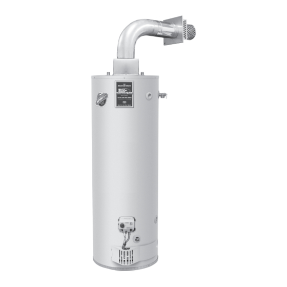
Flammable Vapor Ignition Resistant
Ultra Low NOx Direct Vent Water Heaters
Manual 238-51635-00B REV 10/18
Water Heaters
SERVICE
MANUAL
and Instructions for Service
Troubleshooting Guide
(To be performed ONLY by
qualified service providers)
Models Covered
by This Manual:
URG2DV40S*N
URG2DV50S*N
URG2DV50H*N
ULG2DV50H50*N
(*) Denotes Warranty Years
Save this manual for future reference
Advertisement
Table of Contents

Related Manuals for Bradford White ECO-DEFENDER EURG2DV40S N Series


Summary of Contents for Bradford White ECO-DEFENDER EURG2DV40S N Series
- Page 1 Flammable Vapor Ignition Resistant Water Heaters Ultra Low NOx Direct Vent Water Heaters SERVICE MANUAL Troubleshooting Guide and Instructions for Service (To be performed ONLY by qualified service providers) Models Covered by This Manual: URG2DV40S*N URG2DV50S*N URG2DV50H*N ULG2DV50H50*N (*) Denotes Warranty Years Manual 238-51635-00B REV 10/18 Save this manual for future reference...
-
Page 2: Table Of Contents
UDV Series Ultra Low NO Direct Vent Water Heaters Table of Contents Page UDV SVC Procedure Introduction ..........................4 How to Use This Manual......................4 Tools Required for Service .......................5 Troubleshooting.........................6 Burner Inspection, Cleaning & Replacement .................9 Pilot Testing, Cleaning & Replacement ..................11 Gas Control Testing &... - Page 3 UDV Series WARNING: If the information in these instructions is not followed exactly, a fire or explosion may result causing property damage, DANGER personal injury, or death. Do not store or use gasoline or other flammable, combustible, or corrosive vapors and liquids in FOR YOUR SAFETY the vicinity of this or any other appliance.
-
Page 4: Introduction
UDV Series Introduction The new Bradford White UDV water heaters are designed to provide reliable performance with enhanced standard features. Design features include reliable standing pilot ignition system, enhanced diagnostics, simplified servicing, certified FVIR technology, and Ultra Low NO emissions. -
Page 5: Tools Required For Service
In some difficult to diagnose conditions, it may be necessary to isolate the heater from the vent system to determine the problem. Contact the Bradford White technical support group immediately if diagnosis cannot be made using the methods described in this service manual. - Page 6 DV Series Troubleshooting V1 Observe green LED indicator on electronic gas control. Status flash codes are displayed with a three second pause before repeating. Check and repair the system as noted in the troubleshooting table below. LED Status Control Status Probable Cause Service Procedure If the pilot will not stay lit...
- Page 7 UDV Series Troubleshooting V1 Observe green LED indicator on electronic gas control. Status flash codes are displayed with a three second pause before repeating. Check and repair the system as noted in the troubleshooting table below. LED Status Control Status Probable Cause Service Procedure Four flashes...
- Page 8 UDV Series Troubleshooting V2 Observe colored LED indicator on electronic gas control. Status flash codes are displayed with a three second pause before repeating. Check and repair the system as noted in the troubleshooting table below. LED Status Control Status Probable Cause Service Procedure If the pilot will not stay lit...
-
Page 9: Burner Inspection, Cleaning & Replacement
UDV SERVICE PROCEDURE I UDV Series Burner Operation Inspection, Cleaning and Replacement Burner Inspection At periodic intervals (every 6 months) a visual inspection should be made of the pilot and main burner for proper operation and to assure no debris is accumulating. Pilot flame should be stable, some causes for an unstable pilot flame are: a) Water heater vent is less than the allowable vent length. - Page 10 UDV SERVICE PROCEDURE I UDV Series Burner Operation Inspection, Cleaning and Replacement Burner Cleaning (cont.) Step 9. Thoroughly inspect the burner surface area and the burner port area and remove any loose debris. Step 10. Unscrew the burner feedline from the main burner inner door.
-
Page 11: Pilot Testing, Cleaning & Replacement
UDV Series UDV SERVICE PROCEDURE II Pilot Testing, Cleaning & Replacement Remove Burner to Gain Access to the Pilot Step 1. Position the gas control knob in the “OFF” position. Step 2. Turn off the gas supply to the water heater. Step 3. - Page 12 UDV Series UDV SERVICE PROCEDURE II Pilot Testing, Cleaning & Replacement Pilot Inspection, Testing and Replacement Step 1. Remove the pilot assembly from the burner (1/4” nut driver). Step 2. Visually inspect the igniter wire for damage. Replace pilot if damaged. Electrode should not be in contact with the pilot hood.
-
Page 13: Gas Control Testing & Replacement
UDV Series UDV SERVICE PROCEDURE III Gas Control Testing and Replacement Line Pressure The gas control is designed for a maximum line pressure of 14.0” W.C. and a minimum line pressure of 1.0” W.C. over the water heater’s rated manifold pressure (check rating plate). - Page 14 UDV Series UDV SERVICE PROCEDURE III Gas Control Testing and Replacement ECO (Energy Cut Out) The Honeywell gas control is designed with an ECO device that will reset. To reset the gas control after a status code (4), turn the gas control knob to the “OFF” position and wait a minimum of (5) minutes before relighting following the instructions located on the lighting instruction label or the lighting instructions located in the installation and operation manual.
- Page 15 UDV Series UDV SERVICE PROCEDURE III Gas Control Testing and Replacement Gas Control Removal from Water Heater Step 1. Position the gas control knob in the “OFF” position. Step 2. Drain the heater to a point below the gas control level. Step 3.
-
Page 16: Thermopile Testing
UDV SERVICE PROCEDURE IV UDV Series Thermopile Testing and Replacement Closed Circuit Thermopile Testing Closed circuit thermopile testing is the preferred method for testing the thermopile. Step 1. Following the lighting instruction label on the heater, proceed to light the pilot and allow to operate for three minutes. -
Page 17: Igniter, Electrode Testing And Replacement
UDV Series UDV SERVICE PROCEDURE V Igniter, Electrode Testing and Replacement Igniter, Electrode Testing and Replacement Step 1. Remove the outer jacket door. Step 2. Repeatedly depress the igniter button while viewing the pilot through the flame viewing window. If a spark is present, the circuit is OK. -
Page 18: Inner Door Removal And Replacement
UDV Series UDV SERVICE PROCEDURE VI Inner Door Removal and Replacement Inner Door Removal Procedure Step 1. Position the gas control knob in the “OFF” position. Step 2. Remove the outer jacket burner access door. Step 3. Remove the wire clip from the feedline if present. Step 4. - Page 19 UDV Series UDV SERVICE PROCEDURE VI Inner Door Removal and Replacement Inner Door Gasket Replacement Procedure (cont.) Step 10. Use RTV sealant (recommended bead size 1/8”) to secure the inner door gasket to the inner door sections (right & left). Refer to the illustrations on the next page for proper application.
- Page 20 UDV Series UDV SERVICE PROCEDURE VI Inner Door Removal and Replacement Installation of Inner Door with Gasket (cont.) Step 15. Align right side inner door to combustion chamber and verify the fastener holes of the combustion chamber are aligned with right side inner door slotted opening.
-
Page 21: Diptube Inspection & Replacement
UDV Series UDV SERVICE PROCEDURE VII Diptube Inspection and Replacement Diptube Inspection & Replacement WARNING Water Heater components and stored water may be HOT when performing the following steps in this procedure. Take necessary precaution to prevent personal injury. Step 1. Position the gas control knob in the “OFF” position. Step 2. -
Page 22: Anode Inspection & Replacement
UDV Series UDV SERVICE PROCEDURE VII Anode Inspection and Replacement Anode Inspection & Replacement WARNING Water Heater components and stored water may be HOT when performing the following steps in this procedure. Take necessary precaution to prevent personal injury. Step 1. Position the gas control knob in the “OFF”... -
Page 23: Glossary Of Terms
UDV Series UDV Series Glossary of Terms Glossary of Terms Glossary of Terms British Thermal Units British Thermal Units Gallons per Minute Gallons per Minute Hertz Hertz kWhr Kilowatt Hour Kilowatt Hour Light Emitting Diode Light Emitting Diode National Pipe Thread National Pipe Thread Ohms Ohms of resistance... -
Page 24: Parts List
UDV Series Parts List 1. Venting Package 10. Heat Trap Inlet 20. Main Burner Orifice Complete 11. Inlet Diptube 21. Feedline Clip 2. Venting Protection 12. T&P Valve 22. Right Side Inner Door Screen 13. ¾ NPT Plug (“H” Models 23.