Table of Contents
Advertisement
Quick Links
Service and Troubleshooting
Standard and Remote Applications with LED Controlboard
This manual is to be used by qualified, professionally
trained HVAC technicians only. Goodman does not assume
any responsibility for property damage or personal injury
due to improper service procedures or services performed
by an unqualified person.
required in the repair and who is equipped with the proper
ONLY PERSONNEL THAT HAVE BEEN TRAINED TO INSTALL,
ADJUST, SERVICE, MAINTENANCE OR REPAIR (HEREIN-
AFTER, "SERVICE") THE EQUIPMENT SPECIFIED IN THIS
MANUAL SHOULD SERVICE THE EQUIPMENT. THE MANU-
FACTURER WILL NOT BE RESPONSIBLE FOR ANY INJURY
OR PROPERTY DAMAGE ARISING FROM IMPROPER SER-
VICE OR SERVICE PROCEDURES. IF YOU SERVICE THIS
UNIT, YOU ASSUME RESPONSIBILITY FOR ANY INJURY OR
PROPERTY DAMAGE WHICH MAY RESULT. IN ADDITION, IN
JURISDICTIONS THAT REQUIRE ONE OR MORE LICENSES
TO SERVICE THE EQUIPMENT SPECIFIED IN THIS
MANUAL, ONLY LICENSED PERSONNEL SHOULD SERVICE
THE EQUIPMENT.
IMPROPER INSTALLATION, ADJUSTMENT, SERVICING,
MAINTENANCE OR REPAIR OF THE EQUIPMENT SPECIFIED
IN THIS MANUAL, OR ATTEMPTING TO INSTALL, ADJUST,
SERVICE OR REPAIR THE EQUIPMENT SPECIFIED IN THIS
MANUAL WITHOUT PROPER TRAINING MAY RESULT IN
PRODUCT DAMAGE, PROPERTY DAMAGE, PERSONAL
INJURY OR DEATH.
® is a registered trademark of Maytag Corporation or its related companies and is used under license to
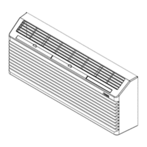
Package Terminal Air Conditioner / Heat Pump
© 2023 Daikin Comfort Technologies Manufacturing, L.P.
Goodman Company, L.P. Houston TX, USA. All rights reserved.
R32 and R-410A
IMPORTANT INFORMATION ..........................................2
PRODUCT IDENTIFICATION ..........................................3
SYSTEM OPERATION ...................................................12
SCHEDULED MAINTENANCE ......................................30
SERVICING .....................................................................33
CHECKING VOLTAGE ................................................43
CHECKING THERMOSTAT AND WIRING ................43
HEATER ASSEMBLY ..................................................44
(HEAT PUMP MODELS ONLY) ..................................45
CAPACITOR CHECK ..................................................45
BLOWER WINDINGS..................................................46
COMPRESSOR WINDINGS .......................................47
OVERLOAD .................................................................48
CHECKING COMPRESSOR EFFICIENCY ..............48
FILTER DRIER REPLACEMENT ...............................48
REVERSING VALVE ...................................................49
ACCESSORIES ..............................................................55
WIRING DIAGRAMS ......................................................56
DO NOT BYPASS SAFETY DEVICES.
TABLE OF CONTENTS
WARNING
RS4200007
January 2023
Advertisement
Table of Contents

Related Manuals for Maytag Amana PTH153K50 Series


Summary of Contents for Maytag Amana PTH153K50 Series
-
Page 1: Table Of Contents
INJURY OR DEATH. RS4200007 January 2023 © 2023 Daikin Comfort Technologies Manufacturing, L.P. ® is a registered trademark of Maytag Corporation or its related companies and is used under license to Goodman Company, L.P. Houston TX, USA. All rights reserved. -
Page 2: Pride And Workmanship Go Into Every Product To Provide
IMPORTANT INFORMATION IMPORTANT NOTICES RECOGNIZE SAFETY SYMBOLS, WORDS AND This device, which was assembled by Daikin Comfort Technologies Manufacturing, L.P., contains a component that is classified as an LABELS intentional radiator. This intentional radiator has been certified by the FCC: FCC ID TF7M90-1000. And this international radiator has an Pride and workmanship go into every product to provide Industry Canada ID: IC 27830-M901C1000. -
Page 3: Product Identification
PRODUCT IDENTIFICATION NOMENCLATURE 07 3 K 35 A X X X BASIC MODEL TYPE MAJOR/MINOR DESIGN REV. PTC = Standard Cooler PTAC PTH = Standard Heat Pump PTHP DRY = Dehumid Cooler PTAC PMC = Cooler w/ Makeup Air Kit PMH = Heat Pump w/ Makeup Air Kit HEH = High Efficiency Heat Pump HEC = High Efficiency Cooler... - Page 4 SPECIFICATIONS PMC/PMH SERIES 1,6,8,9 Model PMC073J00AXXX PMC093J00AXXX PMC123J00AXXX PMC153J00AXXX Voltage 230/208 230/208 230/208 230/208 Capacity (BTU/h) 6,800/6,700 9,000/8,700 11,800/11,700 14,500/14,400 Amps 3.2/3.2 4.3/4.3 6.0/6.0 7.1/7.1 Watts 565/550 775/760 1,070/1,060 1,460/1,450 12.0/12.1 11.6/11.4 11.0/11.0 9.9/9.9 Kit Fresh Air, CFM 25-35 25-35 25-35 25-35 Kit Dehumidifier (Oz/Hr)
- Page 5 SPECIFICATIONS PTC J/K SERIES 1,7,9,10 Model PTC073J00AXXX PTC074J00AXXX PTC093J00AXXX PTC094J00AXXX PTC123J00AXXX PTC124J00AXXX PTC153J00AXXX PTC154J00AXXX Voltage 230/208 230/208 230/208 230/208 Capacity (BTU/h) 7,000/7,000 7,000 9,200/9,000 9,200 11,900/11,600 11,800 14,800/14,500 14,800 Amps 3.1/3.1 4.1/4.1 6.1/6.1 7.0/7.0 Watts 580/560 790/765 1,080/1,060 1,170 1,480/1,450 1,480 12.8/12.8 12.2/12.1...
- Page 6 SPECIFICATIONS HEC J/K SERIES 1,7,9,10 Model HEC073J00AXXX HEC074J00AXXX HEC093J00AXXX HEC094J00AXXX HEC123J00AXXX HEC124J00AXXX HEC153J00AXXX HEC154J00AXXX Voltage 230/208 230/208 230/208 230/208 Capacity (BTU/h) 7,000/7,000 7,000 9,200/9,000 9,200 11,700/11,400 11,800 14,800/14,500 14,800 Amps 3.1/3.1 4.1/4.1 6.1/6.1 7.0/7.0 Watts 510/505 715/700 980/955 1,015 1380/1340 1,320 13.8/13.6 12.7...
- Page 7 SPECIFICATIONS PTH J/K SERIES COOLING 1,7,9,10 Model PTH073J00AXXX PTH074J00AXXX PTH093J00AXXX PTH094J00AXXX PTH123J00AXXX PTH124J00AXXX PTH153J00AXXX PTH154J00AXXX Voltage 230/208 230/208 230/208 230/208 Capacity (BTU/h) 7,100/7,000 7,300 9,000/9,000 9,000 12,000/11,600 12,000 14,600/14,400 14,600 Amps Watts 570/545 725/720 1,040/1,005 1,060 1,400/1,355 1,405 12.4/12.8 12.5 12.4/12.5 12.4 11.5/11.5...
- Page 8 SPECIFICATIONS HEH J/K SERIES 1,7,9,10 Model HEH073J00AXXX HEH074J00AXXX HEH093J00AXXX HEH094J00AXXX HEH123J00AXXX HEH124J00AXXX HEH153J00AXXX COOLING Voltage 230/208 230/208 230/208 230/208 Capacity (BTU/h) 7,100/7,100 7,300 9,000/9,000 9,100 12,000/11,600 12,100 14,500/14,400 Amps 3.35 Watts 530/515 690/680 1,015/965 1,045 1,355/1,305 13.3/13.7 13.3 13/13.2 11.8/12 11.6 10.7/11 HEATING...
- Page 9 SPECIFICATIONS PMH J/K SERIES COOLING 1,6,8,9 Model PMH073J00AXXX PMH074J00AXXX PMH093J00AXXX PMH094J00AXXX PMH123J00AXXX PMH153J00AXXX Voltage 230/208 230/208 230/208 230/208 Capacity (BTU/h) 6,900/6,700 7,700 8,700/8,700 9,000 11,400/11,200 14,400/14,200 Amps Watts 580/555 740/735 1,055/1,015 1,455/1,430 11.9/12 11.7 11.7/11.8 11.6 10.8/11 9.9/9.9 HEATING Capacity (BTU/h) 6,200/6,100 6,500 7,800/7,600...
- Page 10 SPECIFICATIONS PTH J/K SERIES HEH J/K SERIES PMH & PMC SERIES Nominal Heating (Btu/h) Electric Heater No. of Total Min. Circuit Power Voltage Total Watts Size (Kw) Stage Amps Ampacity (amps) Cord @230V @208V @265V 230/208V 8,500 7,000 2,500/2,040 10.9/9.83 14.1 6 -15 P 230/208V...
- Page 11 VOLTAGE REQUIREMENTS HEATING MODE If the model is a PTC** the unit is an electric heat only unit OPERATING VOLTAGES which means the fan and electric heating element will be the only things that will operate in the heating mode. Use a voltmeter, check the voltage at the outlet.
-
Page 12: System Operation
SYSTEM OPERATION NOTE: • Indoor Ambient Thermistor - The Indoor Ambient The heat pump and electric heat DO NOT operate together, Thermistor senses actual room temperature. it is either in electric heat or heat pump mode. • Indoor/Outdoor Coil Thermistors - In the cooling mode, if the compressor is engaged continuously for CONTROL BOARD CHARACTERISTICS 20 minutes and the Indoor Coil Thermistor is below 30... - Page 13 SYSTEM OPERATION USING THE AMANA APP TO SET UP YOUR PTAC CONNECT APP USER CONTROLS OVERVIEW Where to get the app? PTAC Connect is the mobile app that empowers you to program, via Bluetooth, our new J/K series PTACs. The You can find our app in the Google Play Store and in the app is part of the Goodman Amana PTAC suite of apps.
- Page 14 SYSTEM OPERATION MAKING THE CONNECTION Touching this button will signal the app to scan for all Bluetooth-connectable PTACs. When found the PTAC will Programming your PTAC starts with connecting the app be listed showing the serial number as the main identifier to confirm it is the correct unit you wish to pair with.
- Page 15 SYSTEM OPERATION Once the app is connected to a PTAC, the app’s menu accessor ( , upper right corner) will be visible. Touching the menu accessor will show the app’s list of all available programming options: • Dashboard • Statistics •...
- Page 16 SYSTEM OPERATION Touching the Room setting value brings up the THE APP’S PROGRAMMING SCREENS (OR OPTIONS) configuration screen with the room number settings pre- populated for quick editing. From here you can set the DASHBOARD room number your PTAC is in. The Dashboard contains, among other things, the PTAC’s For most applications you will only need to worry about at-a-glance info (Board Info) and the most frequently used...
- Page 17 SYSTEM OPERATION STATISTICS Touching the Configuration icon brings up the Configuration screen with all PTAC settings. This screen can also be alternatively accessed via the menu (Menu | Configuration This screen displays many useful read-only runtime info Settings). from the PTAC board such as Current Mode, Current Temperature, Setback settings, etc.
- Page 18 SYSTEM OPERATION CONFIGURATION SETTINGS Nearly all the PTAC board’s programmable settings can be configured on this screen (except for the PTAC’s Model and Serial Number, which are configured on another screen, i.e., the Service Board screen). If you would like to find a setting quickly the search bar will help you filter through the many settings available to you.
- Page 19 SYSTEM OPERATION If you have the need to replace a control board, the board’s Model and Serial Number are available here to be configured. Before this setting is available, the C3 (Heat Pump Operation) in the Configuration Settings screen must be to Eo (Service Mode, No Operation).
- Page 20 SYSTEM OPERATION DIAGNOSTICS NOTIFICATIONS The Diagnostics screen allows you to see how the PTAC’s The Notifications screen reports all errors and warnings thermistors are performing. This diagnostic tool is available present on the PTAC board. On this screen, there are two both graphically (in a chart) and numerically (in a table).
- Page 21 SYSTEM OPERATION DIAGNOSTIC LIGHT *NOTE: For high speed fan operation, connect “G” to “GH”. The red and green diagnostic light is located next to the ** NOTE FOR THE B TERMINAL: If unit is a heat pump terminal strip for the wired thermostat connections. If the connect B from stat to B on the board.
- Page 22 SYSTEM OPERATION WIRELESS COMMUNICATIONS PTAC models PT***J/K*** have the option to use a wireless thermostat. Refer to Using the Amana App section for setting up the wireless thermostat. WIRELESS THERMOSTAT Skip these steps if not installing. 1. Select thermostat mounting location about five feet above the floor, on an inside wall, out of direct sunlight, away from sources of radiant heat (lamps, fireplaces, heating and air conditioning equipment,...
- Page 23 SYSTEM OPERATION CONFIGURATION SETTINGS Reference M70/M90 Option Configuration Code Description Option Code Description Conf. Code Code Reverts to L5 (Legacy Chassis Membrane) L5 * Wired Thermostat User Interface Selection Wireless Stat (Self configures at binding) Institutional Lock Wireless Thermostat Follows (Cr) selection if any Follows (Cr) selection if any;...
- Page 24 SYSTEM OPERATION CONFIGURATION SETTINGS Reference M70/M90 Option Option Code Description Configuration Code Description Conf. Code Code 73 - 95, Unrented Cool Setpoint 73 - 95 DEGF 79** 45 - 67, Unrented Heat Setpoint 45 - 67 DEGF 63** 0 ** Not Twinned ** Wireless twinning enabled Twinned...
- Page 25 SYSTEM OPERATION CONFIGURATION SETTINGS Reference M70/M90 Option Option Code Description Configuration Code Description Conf. Code Code Heating Smart Fan ("Auto" Not Available adjusting speed availability in 1 ** Available ** Heating) Health Warning Activation Enable (warnings/lockouts enable) 0 ** Disabled* Sensorless Unoccupied Time (hrs.
- Page 26 SYSTEM OPERATION CONFIGURATION SETTINGS Reference M70/M90 Option Option Code Description Configuration Code Description Conf. Code Code Time un-rented state will revert to 01 - 99, 30* 01 - 99, 30* Minutes rented if network lost Freeze Protection Temp 25 -55, 40* 25 -55, 40* DEGF IAT Weight (Percentage weighting of 0 - 99, 20*...
- Page 27 SYSTEM OPERATION CONFIGURATION SETTINGS Reference M70/M90 Option Option Code Description Configuration Code Description Conf. Code Code 1 ** On only when ID fan running ** On only when ID fan running and room is occupied. Selects Smart Vent op. (w/fan, w/occ., On all the time 100%, etc.) On when room is occupied...
- Page 28 SYSTEM OPERATION CONFIGURATION SETTINGS Reference M70/M90 Option Configuration Code Description Option Code Description Conf. Code Code (Pin 2 on J506, Pin 2 on J507, & Pin 1 on Makeup Air Ventilation J200) Ventilation/Econ/Econ+, per (P0) * Lighting Control Kit Transfer Fan Kit Hydronic Valve / Exterior Heater Acc 2 Relay usage No Function*...
- Page 29 SYSTEM OPERATION CONFIGURATION SETTINGS Reference M70/M90 Option Option Code Description Configuration Code Description Conf. Code Code Hydronic Coil Switch Door Switch Motion Sensor 2 ** Front Desk ** Wired Un-rented Set Back Emergency Hydronic Input Pins IN2 (FD, LS, EHH, door, etc.) Load Shedding Alarm Sensor (normally open option)
-
Page 30: Scheduled Maintenance
SCHEDULED MAINTENANCE NOTE: The compressor does not require maintenance. It is 4. Clean and replace the vent screen, slide the chassis hermetically sealed, permanently lubricated. back into the wall sleeve, secure it in place with six screws and reinstall the front cabinet. MONTHLY MAINTENANCE AND CLEANING INTAKE AIR FILTER To properly maintain the operational performance of your... - Page 31 SCHEDULED MAINTENANCE WALL SLEEVE WATER DRIPPING Clean the wall sleeve while cleaning the unit. The caulking Water will collect in the base pan during high humidity days. around the sleeve should be checked to make sure that This can cause overflow and drip from the outside of the unit. any potential air and water openings around the sleeve AIR SOUNDS are properly sealed.
- Page 32 REFRIGERANT SYSTEM Capillary Tube Check Valve (Open) Process Strainer Capillary Tube Discharge Line Suction Line Condenser Evaporator Suction Line Reversing Valve Compressor...
-
Page 33: Servicing
SERVICING REFRIGERATION SYSTEM SERVICE LEAK TESTING IMPORTANT NOTE: Some models contain R32 refrigerant Refrigerant leaks are best detected with a halide or and can be identified in a couple ways. The model serial electronic leak detector. plate will indicate R32, there is a red label added to the NOTE: Leak detectors must be compatible with R-410A process tube and A2L labels have been added to the unit. - Page 34 SERVICING CHARGING Air in the system causes high condensing temperature and pressure, resulting in increased power input and reduced Charge the system with the exact amount of refrigerant. performance. Refer to the unit nameplate for the correct refrigerant charge. An inaccurately charged system will cause future problems. Moisture chemically reacts with the refrigerant and oil to 1.
- Page 35 SERVICING COOLING PERFORMANCE TEST THERMOMETERS B. Dry bulb temperature of air leaving conditioner. The following precautions are necessary in observing the Thermometer has to be located as illustrated. thermometer readings in the cooling performance test. C. The dry bulb thermometer temperature on the sling 1.
- Page 36 SERVICING EXAMPLE: Assume that a PTH15 is again under 3. Locate the readings listed on the following pages. You test. Proceed as follows and observe test readings as will note that these readings fall within the voltage, simultaneously as possible. watts and amp draw minimum and maximum ranges listed and therefore the unit heating performance 1.
- Page 37 SERVICING COOLING CHANGE OF TEMPERATURE - AIR CONDITIONERS PMC073 PMC074 PMC093 PMC094 PMC123 PMC124 PMC153 PMC154 Model PTC073 PTC074 PTC093 PTC094 PTC123 PTC124 PTC153 PTC154 Temperature Temperature Temperature Temperature Temperature Temperature Temperature Temperature Temperature Across Across Across Across Across Across Across Across Room...
- Page 38 SERVICING DIGITAL BOARD DIAGNOSTICS DIAGNOSTIC STATUS REPORT MODE If a failure is detected on the digital board, there will be a green light constantly lit up. This light is located under the Refer to the diagnostic flash codes on the following page. OFF touch pad button.
- Page 39 SERVICING Status Wireless LED Code Status / Issue (BLUE) (Red/Grn) Flashing Alarm (NO) on IN1 or IN2 Green-L Terminal Flashing Alarm (NC) on IN1 or IN2 Terminal Green-L Flashing Brown out Red-LS Flashing Hyd coil freeze protection Red-LS Flashing Green- Indoor recirculation Flashing Frozen ID coil...
- Page 40 SERVICING Status Wireless Code Status / Issue (Red/Grn) (BLUE) Flashing ICT Sensor bad Red-LS Flashing Wireless device signal loss Red-LS Flashing IDT Sensor bad Red-LS Flashing OCT Sensor bad Red-LS Flashing OAT Sensor bad Red-LS Flashing CDT Sensor bad (old IHD) Red-LS Flashing CST Sensor Bad...
- Page 41 SERVICING Status Wireless Code Status / Issue (Red/Grn) (BLUE) Flashing DigiAir discharge hot Green-L Flashing Green- Room Heat Protection Flashing Frosting indoor coil Red-LS Flashing Too hot indoor coil in heat Red-LS Flashing Green- Load Shedding Flashing Electric discharge too hot Red-LS Flashing DigiAir refrigeration issue...
- Page 42 SERVICING System Unsatisfactory Com plaint No Heat Operating Cooling Pressures Test Method POSSIBLE CAUSE Remedy DOTS IN ANALYSIS GUIDE INDICATE "POSSIBLE CAUSE" • Pow er Failure Test Voltage • • • Blow n Fuse Im pact Fuse Size & Type •...
-
Page 43: Checking Voltage
SERVICING CHECKING VOLTAGE 1. Using a voltmeter, measure the voltage across terminals L1 and L2 of the outlet. 2. No reading - indicates open wiring, open fuse(s), no power or etc. from the unit to fused disconnect service. Repair as needed. CHECKING THERMOSTAT, WIRING AND ANTICIPATOR 1. -
Page 44: Heater Assembly
SERVICING Thermistor Resistance-Temperature Characteristic 180000 160000 140000 120000 100000 80000 60000 40000 20000 100 110 120 130 140 150 160 170 Temperature (deg F) Chart applies to black, red, blue, yellow and green wires; it does not apply to orange wires. CHECKING OCT THERMISTOR 1. -
Page 45: Drain Pan Valve (Heat Pump Models Only)
SERVICING CHECKING HEATER ASSEMBLY 1. With power off to the unit and heater, remove the heaters in question and visually inspect the element for broken condition. Vent 2. Remove the wires from the element and check for Control Lever continuity through the heater. If there is no continuity the heater needs to be replaced. -
Page 46: Checking Fan And Motor Blower Windings
SERVICING Capacitor Capacitor Capacitor CAPACITANCE (MFD) = 2650 X AMPERAGE VOLTAGE If the value obtained is not within 10% of the rating printed on the capacitor, replace. 35.0 CHECKING FAN AND MOTOR BLOWER WINDINGS Blower Wheel, Blower Motor, Fan Blade 1. -
Page 47: Compressor Windings
SERVICING 8. Remove the two screws on the left side panel The auto reset fan motor overload is designed to protect securing the motor panel assembly, Figure E. the motor against high temperature and high amperage conditions by breaking the common circuit within the motor, similar to the compressor internal overload. -
Page 48: Overload
SERVICING COMPRESSOR GROUND TEST CHECKING COMPRESSOR EFFICIENCY If the voltage, capacitor, overload and motor windings test The reason for compressor inefficiency is broken or fail to show the cause for failure. damaged suction and/or discharge valves, or scroll flanks on Scroll compressors, reducing the ability of the With no power, wire a test cord to line voltage (L1 &... -
Page 49: Reversing Valve
SERVICING If no voltage is registered to the coil, check the operation of the reversing relay and the continuity of the connecting wires. If voltage is registered at the coil, tap the valve body lightly while switching the system from HEATING to COOLING etc. - Page 50 SERVICING OUTDOOR COIL 1. Remove the chassis from the wall sleeve. 2. After capturing the refrigerant from the system, debraze the inlet and discharge tubing from the outdoor coil. 3. Remove all screws from the sides of the outdoor coil securing the shroud to the coil.
- Page 51 SERVICING The DigiAIR™ compressor/dehumidification process is the condenser coil for re-evaporation to the outside air. controlled both by a humidity sensor and temperature Excess condensate is drained into the PTAC’s wall case sensor that monitor the outdoor environment. The from which it can drain either to the outside through the DigiAIR™...
- Page 52 SERVICING 3. Outside Makeup air volumes of up to 75 CFM. 4. Drier room conditions (lower RH %) usually means that room occupants will feel comfortable at higher sensible temperatures saving PTAC operational costs. 5. Optional 250 watt electric heater to warm colder outside air when needed.
- Page 53 SERVICING If local codes allow for the property (or individual room) ventilation exhaust system to be powered off in extreme WARNING weather conditions (very cold weather, dust storms etc.) or when the room becomes unoccupied, the DigiAIR™ HIGH VOLTAGE module can be powered off and the fan will cease Disconnect all power before servicing.
- Page 54 SERVICING 5. Also inspect and clean the vent door as needed to 5. On 115 volt or 230/208 volt units disconnect the white remove material that can restrict air flow into the lead from the LINE 1 terminal on the control board DigiAIR module.
-
Page 55: Accessories
ACCESSORIES Accessory Part Numbers Description Antenna DT01G Antenna Generic Radio GT01G Circuit Breaker Kit(208/230Vonly) CBK15C, CBK20C and CBK30C Condensate Drain Kit DK900D Condenser Baffle Kit DGK1B Door Sensor DD01G Duct Extention EDK02B Hard Wire kit Quick Disconnect 208/230v PTQC3A Hard Wire Kit PTPWHWK4 Hard Wire Kit Quick Disconnect 265v PTQC4A... -
Page 56: Wiring Diagrams
WIRING DIAGRAMS IT IS ESSENTIAL THAT INDOOR AND OUTDOOR UNITS BE PROPERLY MATCHED. FAILURE TO FOLLOW THESE INSTRUCTIONS OR TO PROPERLY MATCH EVAPORATORS AND CONDENSERS CAN RESULT IN UNIT DAMAGE, PROPERTY DAMAGE AND/OR PERSONAL INJURY. NO WARRANTY CLAIM WILL BE HONORED FOR MIX-MATCHED SYSTEMS THAT FAIL TO ADHERE TO THE SPECIFIED PISTON SIZE. - Page 57 WIRING DIAGRAMS IT IS ESSENTIAL THAT INDOOR AND OUTDOOR UNITS BE PROPERLY MATCHED. FAILURE TO FOLLOW THESE INSTRUCTIONS OR TO PROPERLY MATCH EVAPORATORS AND CONDENSERS CAN RESULT IN UNIT DAMAGE, PROPERTY DAMAGE AND/OR PERSONAL INJURY. NO WARRANTY CLAIM WILL BE HONORED FOR MIX-MATCHED SYSTEMS THAT FAIL TO ADHERE TO THE SPECIFIED PISTON SIZE.