Table of Contents

Related Manuals for Nectre Fireplaces 2000


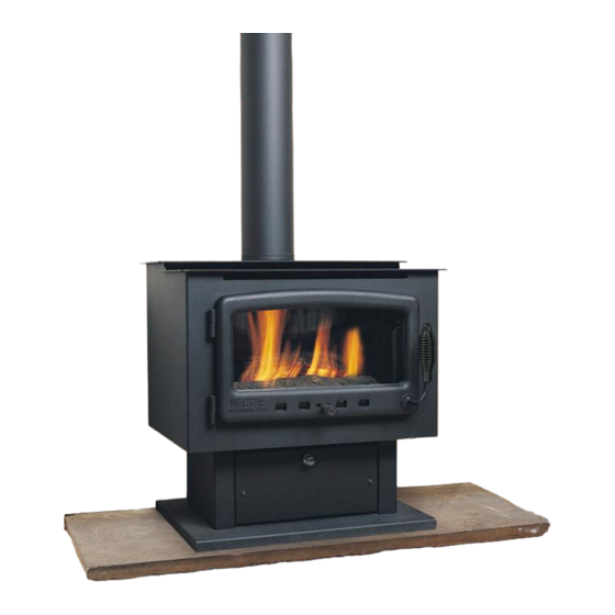
Summary of Contents for Nectre Fireplaces 2000
- Page 1 NECTRE 2000 FREESTANDING SPACE HEATER SERVICE INSTRUCTIONS Do not modify this appliance. Freestanding gas appliance Natural gas only. Approval no.AGA 5954G Warning – Servicing shall be carried out only by authorized personnel.
- Page 2 WARNING The Nectre 2000 space heater has a primary safety glass fitted in front of the glass door. This safety glass is fitted to this appliance to reduce the risk of injury from burns and at no time should this glass be permanently removed.
-
Page 3: Table Of Contents
CONTENTS DATA PLATE............................4 DIMENSIONS ............................4 INSTALLATION CODES ........................5 FLUE SIZES AND COWLS ......................5 FLUE TERMINATION LOCATION ....................5 SEQUENCE OF OPERATION ......................6 FAULT GUIDE ............................7 MEDIA INSTALLATION ........................9 COMMISSIONING PROCEDURE ....................10 BURNER PRESSURE ADJUSTMENT ..................11 IGNITION ADJUSTMENTS (SPARK GAPS) ................ -
Page 4: Data Plate
DATA PLATE Natural Gas Jet 2.95mm High TPP .52Kpa Consumption 28Mj/h TPP .30Kpa Consumption 20Mj/h Working pressure required to operate appliance Natural Gas 1.13Kpa- 5.00Kpa Installation must meet Australian gas codes AS/NZS 5601.1-2013. DIMENSIONS INSTALLATION CLEARANCES- GAS CONNECTION – 15mm (1/2”) Compression union. clearances from combustible materials Rear 75mm... -
Page 5: Installation Codes
INSTALLATION CODES • Note appliance gas type – Natural gas only available. • Installers – Please ensure the installation and instruction manuals supplied with this appliance are supplied to the customer and the customer is trained on how to operate the appliance correctly. -
Page 6: Sequence Of Operation
SEQUENCE OF OPERATION Turning the heater ON 1. Check that the gas and electricity is turned on. 2. Open the fold down control panel in the front of the pedestal. (The glass door is fixed and does not open). There are three switches to operate the fire: ������... -
Page 7: Fault Guide
FAULT GUIDE FAULT CAUSE REMEDY Igniter Sparks but No Gas Check supply no Ignition Purge lines. Electricity not ON Igniter does not Check electricity supply. spark and fan does Fuse blown not run Replace fuse (check why fuse blew). Fault in wiring Check wiring. - Page 8 fire after waiting 30 seconds. Incorrect pressure Flame abnormality Check gas pressure high and low. Dirt in jet or burner. Clean jet and burner. Log arrangement incorrect. Check log and ember effect against instructions.
-
Page 9: Media Installation
MEDIA INSTALLATION • Media must be setup as per instructions. • The media is designed and shaped to correctly locate and remain in the correct position. • Do not add extra media, or combine media types. • Only the approved supplied media is to be used. •... -
Page 10: Commissioning Procedure
• Place the right hand lower log (5) on to its two location studs and the Y shaped left lower log (4) on to its locating studs. • Place pieces of ember wool in the two cut outs of the base board and on top of visible parts of the base bard. -
Page 11: Burner Pressure Adjustment
BURNER PRESSURE ADJUSTMENT Burner test point pressures must be set whilst appliance is running. Min pressure adjustment screw Inlet gas pressure Burner pressure test point test point Max pressure adjustment nut 1. Turn appliance off at remote control. 2. Loosen burner pressure test point screw and fit manometer to barb. 3. -
Page 12: Ignition Adjustments (Spark Gaps)
IGNITION ADJUSTMENTS (SPARK GAPS) 1. The ignition gap is factory set and fixed on all burners and should not be adjusted. 2. In the event of a gas type conversion the correct pilot and pilot orifice must be used. Spark rod – eight approx.. 3- Flame sensing rod- runs across 4mm above front burner rail, burner, height approx. -
Page 13: Door Glass & Glass Seal Replacement
DOOR GLASS & GLASS SEAL REPLACEMENT Glass and seal replacement - Refer directly to Glen Dimplex Australia Pty Ltd. Refer to door fitment for checking of seals and glass DOOR REMOVAL & REPLACEMENT 1. Turn off mains power to appliance. 2. -
Page 14: Burner
BURNER • To access the burner remove the log/coals. Examine it for any damage and check the venturi at the rear for lint and dust. Carefully clean as required. • Ensure that the main injector is located centrally with respect to the venturi. •... -
Page 15: Wiring Diagram
WIRING DIAGRAM CONVERSION DETAILS Appliance available as Natural gas only. -
Page 16: Parts List
PARTS LIST Valve (SIT 843 SIGMA) Injector Burner Ignition pack/ gas control (SIT 579.402) - Page 17 GLEN DIMPLEX AUSTRALIA PTY LTD ABN 69 118 275 460 Head Office/Factory/Showroom 1340 Ferntree Gully Rd. Scoresby Vic 3179 Ph: (03) 8706 2000 Fax: (03) 8706 2001 E-mail: info@realflame.com.au Richmond - VIC Showroom 300 Swan St. Richmond Vic 3121 Ph: (03) 9428 4443 Fax: (03) 9428 4445...