Advertisement
Quick Links
EPC4 Quick Reference Guide
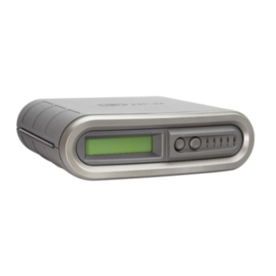
Graphical Overview
Front View
Accessories Included
1 - 6ft (2m) Power Cable 90°
(U.S. Models Only)
Recovery Utility
Pressing the Recovery Button on the rear of the unit will cause the EPC4
to boot to its Recovery Mode. This operation will automatically run a
check disk process to attempt to resolve any problems with the disk or
file system and then reboot into Normal Mode. A log of any changes will
be created by the check disk process.
Open Enclosure To Access Internal IO Ports
• To open enclosure, pull / push enclosure open latch toward the front IO.
• While the open enclosure latch is in the forward position, separate bottom and top housing.
Rear View
1 - 15ft (5m) Network Cable
Front Panel Buttons and LED's
1 – LCD Display
2 – LCD Display Control: NEXT
1
3 – LCD Display Control: SELECT
Back Panel Buttons and Ports
6
7
5
4
* Note: The DVI port should only be used for setup, maintenance and troubleshooting. It is not intended for use
during normal operation.
Internal Ports and Slots
2
1
3
6
Lock / Secure Enclosure
• With EPC4 enclosure closed, pull out lock latch until "Locked" is
displayed
• Use one of the following to secure the device
• Standard Pad lock with a bolt diameter no less than .200" and no
greater than .280"
• Tamper Evident Zip Tie
• Kensington Lock
• Ensure Kensington lock is inserted through the rear IO and into the
Lock Latch
2
3
4
5
6
7
3
2
1
1 – Power Socket 110-220V 50-60Hz
2 – Power On/Off Button
3 – Recovery Utility Button
4 – DVI Port *
5 – PCI-e Slot (Modem Optional)
6 – Lock Latch
7 – Cable Retention (Cables must route behind
door to be retained)
4
5
1 – 2x Network LAN 10/100/1000
Port, not powered
2 – 4 x Serial Port RS232
3 – 2x Powered Serial Ports RS232
+12V/500mA each on RTS
4 – 4 x USB Ports +5V/500mA each
5 – PCI-e Expansion Slot
6 – SSD, MO-297 SATA 3.0Gb/s
NCR P/N 497-0476345
Rev C
4 – Power LED
Solid Red = AC plugged in but
not powered on
8
Solid Blue = Booting
Solid Green = After boot up
5 – Status LED
Solid Red = Initial
Solid Green = After boot up
6 – HDD LED
Blinking Blue = Activity
7 – Network 1 LED
Blinking Orange = Activity
8 – Network 2 LED
Blinking Orange = Activity
Advertisement

Related Manuals for NCR EPC4


Summary of Contents for NCR EPC4
- Page 1 Recovery Utility * Note: The DVI port should only be used for setup, maintenance and troubleshooting. It is not intended for use Pressing the Recovery Button on the rear of the unit will cause the EPC4 during normal operation. to boot to its Recovery Mode. This operation will automatically run a check disk process to attempt to resolve any problems with the disk or file system and then reboot into Normal Mode.
- Page 2 Problem Suggestions The unit will not • Check to make sure the power cord is firmly plugged in to both the EPC4 and AC power on power outlet. • Press and release the power button to turn the EPC4 on. Do not hold the power EPC4 Product Highlights button down longer than one second.
- Page 3 (UL, CSA, TUV, VDE) oder jenen die von der NCR empfohlen werden, angeschlossen werden. • To avoid a possibility of electrical shock, be sure to connect the power cord to the EPC4 before connecting it to the A/C power outlet.
- Page 4 Operation of this equipment in a residential area is likely to cause interference in which case the user will be required to correct the interference at his own expense. NCR is not responsible for any radio or television interference caused by unauthorized modification of this equipment or the substitution or attachment of connecting cables and equipment other than those specified by NCR.