Table of Contents
Advertisement
Quick Links
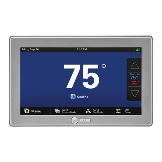
ComfortLink™ II XL1050
Communicating Connected Control
TZON1050 Installation Guide
ALL phases of this installation must comply with NATIONAL, STATE AND LOCAL CODES
IMPORTANT — This Document is customer property and is to remain with this unit.
These instructions do not cover all variations in systems or provide for every possible contingency to be met in connection with
the installation. Should further information be desired or should particular problems arise which are not covered sufficiently
for the purchaser's purposes, the matter should be referred to your installing dealer or local distributor.
18-HD80D1-6E-EN
Advertisement
Table of Contents

Related Manuals for Trane TZON1050


Summary of Contents for Trane TZON1050
- Page 1 ComfortLink™ II XL1050 Communicating Connected Control TZON1050 Installation Guide ALL phases of this installation must comply with NATIONAL, STATE AND LOCAL CODES IMPORTANT — This Document is customer property and is to remain with this unit. These instructions do not cover all variations in systems or provide for every possible contingency to be met in connection with the installation.
-
Page 2: Table Of Contents
Installation Guide Contents Advanced Operation ............. 20 Safety ................2 Product Specifications ........... 3 Control Response Rate ........20 General Information ............3 Dehumidification ..........20 Overview ............... 3 Dehumidifier Operation ........20 Contents ..............3 Dual Fuel Operation ..........20 Accessories ............ -
Page 3: Product Specifications
XL 1050 Product Specifications SPECIFICATION DESCRIPTION Product Model TZON1050AC52ZC Product Wi-Fi, ComfortLink™ II Control Size Product: 7.2” x 4.5” x 1.2”; Display 6.1” x 3.3” (WxHxD) Configurations Heat Pump, Heat/Cool, Dual Fuel, Heat Only, Cooling Only Maximum Number of Stages 5 Stages Heat, 2 Stages Cooling Storage/Operating Temperature -40°F to 175°F, 5% to 95% RH non-condensing... -
Page 4: Installation
Installation Guide Installation Network Connections To take advantage of the full range of features on the 1050 Location Control, it should be connected to the Internet. This is The 1050 Control is designed for installation in climate possible using either a wireless or a wired connection. controlled living spaces. -
Page 5: Wiring
XL 1050 Mounting FIGure 3. MOuNT THe SuB-BASe TO THe WALL Follow these steps to mount the 1050 Control to the wall. 1. Turn OFF all power to heating and cooling equipment. 2. If an existing thermostat is being replaced: a. -
Page 6: Field Wiring Connection Diagrams
Installation Guide Field Wiring Connection Diagrams Communicating Indoor and Outdoor 24V System w/Relay Panel Communicating Controls Wiring Diagram Communicating Controls w/Relay Panel Wiring Diagram 1050 1050 COMFORT COMFORT CONTROL CONTROL INDOOR UNIT COMMUNICATING COMMUNICATING INDOOR UNIT OUTDOOR UNIT RELAY PANEL See Indoor and Outdoor unit Installer’s Guides... - Page 7 XL 1050 S9V2 Furnace w/Communicating Outdoor Communicating Controls w/S9V2 Furnace and Comm Outdoor 1050 COMFORT CONTROL S9V2 FURNACE RELAY PANEL See Furnace Installer’s Guide for specific wiring instructions. OUTDOOR UNIT Optional Outdoor Sensor* Optional Remote Sensor* *Caution: Do not run Outdoor/Remote sensor wires in the same bundle with HVAC wires.
-
Page 8: System Setup
1050 Control initiates a 90-120 second power-up guided through the Display, Schedules, Guided Schedule, ® sequence. During the power-up sequence, the Screen Network, Trane Home and Weather configuration screens. Calibration option is available for five seconds (Screen Each of these menus may also be accessed individually. -
Page 9: Group 2 - Zoning Settings
XL 1050 5.3.2 Group 2 - Zoning Settings Zoning settings are only available when a Zone Panel is connected and discovered. Required Steps before enabling zoning: Zone Panel must be powered (24VAC transformer) Zone Panel must be connected to communicating bus (D, B) All non-communicating zone temperature sensors must be connected to corresponding zone slots All communicating zone temperature sensors must be addressed to corresponding zone number All dampers should be installed and connected to corresponding zone slot... - Page 10 Installation Guide MANUAL ZONE SIZING Auto Zone Sizing is the optimal way to determine the amount of air flow into each zone, but this process is not mandatory. Zone sizes can be set manually using the following guidelines. EXAMPLE (highlighted below): A 2-zone, 3-ton AC system is configured to move 1200 CFM. Zone 1 has a 12” zone damper and Zone 2 has a 16”...
-
Page 11: Group 2* - Equipment Settings
XL 1050 5.3.3 Group 2* - equipment Settings * If Zoning is enabled, this group will be called Group 3. OPTIONS MENU ITEM DESCRIPTION [DEFAULT] Compressor Cooling Cycles Per Hour 2 - 6 Cph [3] Select # of cycles per hour during cooling operation 1st Stage Compressor Cooling Cycles Per Hour 2 - 6 Cph [3] Select # of cycles per hour during 1st stage cooling operation... -
Page 12: Group 4* - Accessories Settings
Installation Guide 5.3.5 Group 4* - Accessories Settings * If Zoning is enabled, this group will be called Group 5. MENU ITEM OPTIONS [DEFAULT] DESCRIPTION [No Comm Air Cleaner Discovered], Comm Air Filtration Type Installed Select the filter type installed Cleaner Discovered Air Cleaner, [Media Filter] Number Of Air Cleaners installed... -
Page 13: Group 5* - Comfort Settings
XL 1050 5.3.6 Group 5* - Comfort Settings * If Zoning is enabled, this group will be called Group 6. MENU ITEM OPTIONS [DEFAULT] DESCRIPTION Enable Dehumidification [Enable], Disable Select if enhanced dehumidification features are enabled. Select the maximum amount of overcooling allowed when the Dehumidification Overcooling Limit - Degrees ①... -
Page 14: Group 6* - Airflow Settings
Installation Guide 5.3.7 Group 6* - Airflow Settings * If Zoning is enabled, this group will be called Group 7. All air flow settings are disabled when a communicating variable speed system is applied. Set fan delays on the outdoor unit CDA (communicating display assembly). -
Page 15: Group 7* - Lockout Settings
XL 1050 5.3.8 Group 7* - Lockout Settings * If Zoning is enabled, this group will be called Group 8. An Outdoor Temperature Sensor must be enabled for Lockout settings to be selectable. OPTIONS MENU ITEM DESCRIPTION [DEFAULT] Enables the installer to limit system operation (heating and cooling mode) Quiet Mode [Disable], Enable to meet local daytime and nighttime sound requirements, if necessary. -
Page 16: Indoor Sensor Setup
Dealer Code The Indoor Temperature Setup screen allows the technician When a 1050 Control is connected to Trane Home, a Dealer to view, edit and assign the correct temperature sensor for Code can be entered to auto-populate the dealer’s contact each zone. -
Page 17: Basic Operation - Non-Zoned
XL 1050 Basic Operation – Non-Zoned LOAD VALUE RANGE - COOLING 0-100 Single Stage Compressor PI Control 0-200 Two Stage/VSPD Compressor The 1050 Control uses proprietary control schemes to A Load Value of 50 represents a request of 50% demand provide comfort and energy efficiency. -
Page 18: Stage Thresholds
Installation Guide Stage Thresholds Stage Inhibits The threshold to allow operation is a Load Value greater When the stage threshold is exceeded, a stage inhibit is than 5 and operation is always terminated with a Load applied. The stage inhibit calculates the rate of recovery Value less than 1. -
Page 19: System Mode
XL 1050 System Mode Mode performance, the installing dealer must make the changes to the setup found in the Quiet Mode Set-up The 1050 Control has (5) System Modes which can be document available online. selected: Heating, Cooling, Off, Emergency Heat and Auto. •... -
Page 20: Advanced Operation
Installation Guide Advanced Operation Dehumidifier Operation The 1050 Control has the ability to control a Whole-House Control response rate Dehumidifier through the normally open dry AUX Contacts Allows the user to select a set of higher proportional-integral on the optional Relay Panel. Control options are: control constants to increase the responsiveness of the •... -
Page 21: Lockouts
XL 1050 Lockouts Restrict Compressor The 1050 Control has the following lockouts. AN OUTDOOR Heat Only TEMPERATURE SENSOR MUST BE ENABLED FOR LOCKOUT SETTINGS TO BE AVAILABLE. Lockouts can 70º be enabled in Installer Setup>Lockout Settings. Control Determines 65º • Auxiliary Heat Lockout –... -
Page 22: Humidifier Operation
Installation Guide Humidifier Operation for units with a variable speed indoor blower. When zoning is applied, all dampers open fully on a call for ventilation The 1050 Control has the ability to control a humidifier. only. The ventilation run time per hour can be adjusted to Humidification is only enabled while in heating mode of meet ASHRAE 62.2 standards. -
Page 23: Zoning
The 1050 Control is zoning capable with the ability to control • Trane or American Standard manufactured indoor unit single stage, multi stage and variable speed equipment. with a variable speed blower (branded Geothermal package units and oil furnaces are not supported) The 1050 integrates modulating damper control within system operation without jeopardizing system reliability. -
Page 24: Capacity Request (System Lv)
Installation Guide 8.3.3 Damper position Example for determining System Mode: The position of the modulating dampers is determined by ZONE 1 ZONE 2 ZONE 3 ZONE 4 the amount of capacity each zone is requesting. Zone LV 60 (clg) 50 (clg) 60 (htg) 50 (htg) The damper position for each same mode calling zone... -
Page 25: Indoor Sensor Setup
XL 1050 • Air Flow Modulation Relief Strategy • The indoor blower speed is controlled based on The relief strategy employed by the 1050 successfully the type of equipment installed and the air flow manages excess air without affecting the efficiency or capabilities of the calling zones…insert chart reliability of the applied heating/cooling system. -
Page 26: Diagnostic Tools
Installation Guide Diagnostic Tools Test Modes Access Test Modes by navigating to Service Menu>Test Modes. All test modes will terminate automatically after 60 minutes or can be terminated manually at any time. 9.1.1 Non-Variable Speed MODE SETTINGS DESCRIPTION Test Blower 50%, 100% Energize indoor blower at the selected speed Stage 1... -
Page 27: Damper Test Mode
XL 1050 9.1.3 Damper Test Mode 9.3.2 Summary Table Damper Test Mode gives the user the ability to open The 1050 Control has a Summary Table which lists all specific dampers to verify the dampers are performing the communicating devices that have been discovered. properly. -
Page 28: System Report
Installation Guide System report restore Factory Defaults The System Report Screen provides technicians with This feature will delete all saved settings, both user and important system operational data in one, concise screen. installer, and restore the 1050 Control to its factory default The data is provided in real-time and updates as the data settings. -
Page 29: Troubleshooting
XL 1050 10. Troubleshooting SYMPTOM POSSIBLE CAUSES ACTION 1050 Control displays an alert on A critical or major alert is present. Navigate to the Diagnostic screen on the 1050 Control the screen. for a Problem Description and Possible Cause. Display will not come on Loss of 24VAC between R &... - Page 30 Alerts screen. zoned system Time set on 1050 Control 1050 Control is connected to Trane Home and Correct the time zone set on Trane Home account. changes every 24 hours. the time zone set on Trane Home account is incorrect.
-
Page 31: Notices
XL 1050 11. Notices 11.1 FCC Notice FCC ID: XVRZON1054 INFORMATION TO USER This device complies with Part 15 of the FCC Rules. Operation is subject to the following two conditions: (1) This device may not cause harmful interference and (2) This device must accept any interference received, including interference that may cause undesired operation. - Page 32 For more information, please visit trane.com or tranetechnologies.com. Trane has a policy of continuous data improvement and it reserves the right to change design and specifications without notice. We are committed to using environmentally conscious print practices.