
Related Manuals for MQ Power ULTRA-SILENT DCA-25USI Series


Summary of Contents for MQ Power ULTRA-SILENT DCA-25USI Series
- Page 1 OPERATION & PARTS MANUAL DCA-25USI ULTRA-SILENT SERIES GENERATOR PARTS LIST NO. M1871400104 Revision #0 (05/06/04) THIS MANUAL MUST ACCOMPANY THE EQUIPMENT AT ALL TIMES.
- Page 2 Discount-Equipment.com is your online resource for quality parts & equipment. Florida: 561-964-4949 Outside Florida TOLL FREE: 877-690-3101 Need parts? Click on this link: http://www.discount-equipment.com/category/5443-parts/ choose one of the options to help get the right parts and equipment you are looking for.
- Page 3 PAGE 2 — DCA-25USI — OPERATION AND PARTS MANUAL (STD) — REV. #0 (05/10/04)
-
Page 4: Table Of Contents
TABLE OF CONTENTS MQ POWER DCA-25USI MQ POWER DCA-25USI MQ POWER DCA-25USI MQ POWER DCA-25USI MQ POWER DCA-25USI COMPONENT DRA COMPONENT DRA COMPONENT DRAWINGS WINGS WINGS WINGS COMPONENT DRA COMPONENT DRA WINGS AC GENERA AC GENERA AC GENERA AC GENERATOR AC GENERA Generator Assembly .......... -
Page 5: Dca-25Usi Specifications
DCA-25USI — SPECIFICATIONS t a r i f i o i t i v l e i f , d l l e s a l i t r o t i t c r a t h t i l a r a t l a t l... -
Page 6: Dimensions
DCA-25USI — DIMENSIONS (SIDE AND FRONT) Figure 1. Dimensions DCA-25USI — OPERATION AND PARTS MANUAL (STD) — REV. #0 (05/10/04) — PAGE 7... -
Page 7: Safety Message Alert Symbols
NOTE instructions for the safe and efficient operation of the MQ Power Model DCA-25USI ULTRA-SILENT™ GENERATOR. Explosive Fuel Before using this GENERATOR, ensure that the operating... - Page 8 DCA-25USI — SAFETY MESSAGE ALERT SYMBOLS Accidental Starting Respiratory Hazard ALWAYS place the engine ON/OFF switch in the OFF position, when the trowel is not ALWAYS wear approved respiratory protection. in use. Over Speed Conditions Sight and Hearing hazard NEVER tamper with the factory settings of the engine governor or settings.
-
Page 9: Rules For Safe Operation
■ NEVER use accessories or attachments, which are not ■ NEVER stand in water while AC power from the generator recommended by MQ Power for this equipment. Damage to is being transfer to a load. the equipment and/or injury to user may result. - Page 10 DCA-25USI — RULES FOR SAFE OPERATION ■ ALWAYS make sure that electrical circuits are properly DANGER DANGER DANGER: DANGER DANGER grounded per the National Electrical Code (NEC) and local codes before operating generator. Severe injury or death! by electrocution can result from operating an ungrounded generator.
- Page 11 DCA-25USI — RULES FOR SAFE OPERATION Battery ■ NEVER run engine without air filter. Severe engine damage may occur. The battery contains acids that can cause injury to the eyes ■ ALWAYS service air cleaner frequently to prevent engine and skin. To avoid eye irritation, always wear safety glasses. Use well insulated gloves when picking up the battery.
-
Page 12: Towing Safety Precautions
DCA-25USI — RULES FOR SAFE OPERATION ■ Avoid sharp turns. Towing Safety Precautions ■ Trailer should be adjusted to a level position at all times CAUTION: CAUTION: CAUTION: CAUTION: CAUTION: when towing. ■ Raise and lock trailer wheel stand in up position when Conform to Department of Transportation transporting. - Page 13 DCA-25USI — INSTALLATION Figure 2. Typical Generator Grounding Application PAGE 14 — DCA-25USI — OPERATION AND PARTS MANUAL (STD) — REV. #0 (05/10/04)
- Page 14 DCA-25USI — INSTALLATION Generator Grounding Outdoor Installation To guard against electrical shock and possible damage to Install the generator in a clear area. Make sure the generator the equipment, it is important to provide a good EARTH is on secure level ground so that it cannot slide or shift ground.
- Page 15 DCA-25USI — TOWING SAFETY PRECAUTIONS ■ ALWAYS attach trailer’s safety chain to bumper of towing Towing Safety Precautions vehicle. CAUTION CAUTION CAUTION: CAUTION CAUTION ■ ALWAYS make sure the vehicle and trailer directional, Check with your local county or state safety backup, brake, and trailer lights are connected and working properly.
-
Page 16: Trailer Specifications
DCA-25USI — TRAILER SPECIFICATIONS CAUTION CAUTION CAUTION: 5. Frame Width - Measurement is from fender to fender CAUTION CAUTION 6. Jack Stand - Trailer support device with maximum pound ALWAYS make sure the trailer is in good requirement from the tongue of the trailer. operating condition. -
Page 17: Generator Decals
DCA-25USI — GENERATOR DECALS The DCA-25USI generator is equipped with a number of safety decals. These decals are provided for operator safety and maintenance information. The illustration below and on the preceding page show the decals as they appear on the machine. - Page 18 DCA-25USI — GENERATOR DECALS DCA-25USI — OPERATION AND PARTS MANUAL (STD) — REV. #0 (05/10/04) — PAGE 19...
-
Page 19: General Information
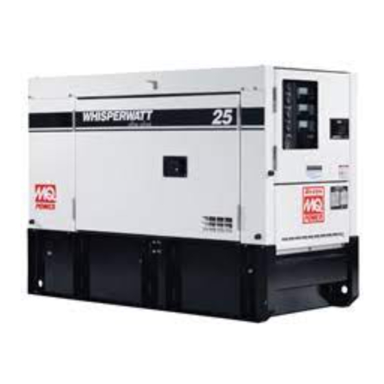
Generator " Open-Delta " excitation system. The open delta system consist of The MQ Power Model DCA-25USI (Figure 4) is a 20 kW an electrically independent winding wound among stationary generator that is designed as a high quality portable (requires windings of the AC output section. - Page 20 DCA-25USI — MAJOR COMPONENTS f f u r e l r o t e t t r o t l o r Figure 4. Major Components i t a DCA-25USI — OPERATION AND PARTS MANUAL (STD) — REV. #0 (05/10/04) — PAGE 21...
- Page 21 DCA-25USI — GENERATOR CONTROL PANEL Figure 5. Generator Control Panel Located behind the generator control panel is the Generator The definitions below describe the controls and functions of Control Box . This box contains some of the necessary the DCA-25USI " Generator Control Panel " (Figure 5). electronic components required to make the generator Main Circuit Breaker –...
- Page 22 DCA-25USI — ENGINE OPERATING PANEL The definitions below describe the controls and functions of the DCA-25USI " Engine Operating Panel " (Figure 6). Panel Light - Normally used in dark places or at night. When activated, panel will luminate. When the generator is not in use, turn the panel light switch to the OFF position.
-
Page 23: Output Terminal Panel Familiarization
DCA-25USI — OUTPUT TERMINAL PANEL FAMILIARIZATION Output Terminal Panel Output Terminal Panel Familiarization The Output Terminal Panel (Figure 7) shown below is located The Output Terminal Panel (Figure 7) is provided with the on the right side of control panel. Lift up on the cover to gain following: access to receptacles and terminal lugs. - Page 24 DCA-25USI — OUTPUT TERMINAL PANEL FAMILIARIZATION 120 VAC GFCI Receptacles Each auxilliary receptacle is protected by a 50 amp circuit breaker. These breakers are located directly above the GFCI There are two 120 VAC, 20 amp GFCI (Duplex Nema 5-20R) receptacles.
- Page 25 DCA-25USI — OUTPUT TERMINAL PANEL FAMILIARIZATION Blower Fan Connecting Loads This unit has an intake fan located at the rear of the machine Loads can be connected to the generator by using the Output to draw outside air into the cabinet to cool the engine. The Terminal Lugs or the convienience receptacles.
-
Page 26: Load Application
DCA-25USI — LOAD APPLICATION Single Phase Load Three Phase Load When calculating the power requirements for 3-phase power Always be sure to check the nameplate on the generator and equipment to insure the wattage, amperage, frequency, use the following equation: and voltage requirements are satisfactorily supplied by the generator for operating the equipment. - Page 27 DCA-25USI — GENERATOR OUTPUTS Voltage Selector Switch Generator Amperage The voltage selector switch (Figure 15) is located above Table 7 describes the generator’s current output capability for both 1Ø-phase and 3Ø phase applications. the Output Terminal Panel Hard Wire Hook-up Panel. It has been provided for ease of voltage selection.
-
Page 28: Gauge Reading
DCA-25USI — GAUGE READING How to Read the Output Terminal Gauges. Reading Amperage The gauges and selector switches on the control panel To determine the amperage at a terminal lug, set the DO NOT effect the generator output. They are provided to AC Ammeter Change-Over Switch to the appropriate setting (Figure 19) to activate the AC Ammeter Gauge help observe how much power is being supplied at the UVWO... - Page 29 DCA-25USI — OUTPUT TERMINAL PANEL CONNECTIONS 3Ø 208V/1Ø 120V Output Terminal Lug Voltages Output Terminal Lug Voltages Various output voltages can be obtained using the Output 1. Place the voltage selector switch in the 3Ø 240/139 Terminal Lugs . The voltages at the terminals are depen- position as shown in Figure 22.
- Page 30 DCA-25USI — OUTPUT TERMINAL PANEL CONNECTIONS 3Ø 480/277V Output Terminal Lug Voltages 1Ø 240/120V Output Terminal Lug Voltages 1. Place the voltage selector switch in the 3Ø 480/277V 1. Place the voltage selector switch in the 1Ø 240/120V position as shown in Figure 24. position as shown in Figure 26.
- Page 31 DCA-25USI — PRE-SETUP Fuel Check Circuit Breakers DANGER: DANGER: DANGER: DANGER: DANGER: To protect the generator from an overload, a 3-pole, 60 amp, main circuit breaker is provided to protect the U,V, and W Fuel spillage on a hot! engine can cause a Output Terminal Lugs from overload.
- Page 32 DCA-25USI — PRE-SETUP Refueling Procedure: Open cabinet doors on the generator. Locate and remove the fuel tank cap and fill tank (Figure 31). DANGER: DANGER: DANGER: DANGER: DANGER: Diesel fuel and its vapors are dangerous to your health and the surrounding environment. Avoid skin contact and/or inhaling fumes.
- Page 33 DCA-25USI — PRE-SETUP Coolant (Ethylane Glycol [Green] / Water — 50/50 mix) Use only drinkable tap water. If hard water or water with When the antifreeze is mixed with NOTE many impurities is used, the inside of the engine and radiator water, the antifreeze mixing ratio may become coated with deposits and cooling efficiency must be less than 50%.
- Page 34 DCA-25USI — PRE-SETUP Battery When connecting battery do the following: This unit is of negative ground DO NOT connect in reverse. 1. NEVER connect the battery cables to the battery Always maintain battery fluid level between the specified terminals when the ignition switch is in either the marks.
-
Page 35: Generator Start-Up Procedure
DCA-25USI — GENERATOR START-UP PROCEDURE 3. Close all engine enclosure doors (Figure 38). WARNING: WARNING: WARNING: WARNING: WARNING: The engine's exhaust contains harmful emissions. ALWAYS have adequate ventilation when operating . Direct exhaust away from nearby personnel. Before Starting CAUTION: Figure 38. - Page 36 DCA-25USI — GENERATOR START-UP PROCEDURE 6. Turn the ignition key to the START position (Figure 46). 9. The generator's voltage meter (Figure 44) displays the Once the engine starts, release the ignition key and output voltage in VOLTS. allow it to return to the PRE-HEAT/RUN position (Figure 42).
- Page 37 DCA-25USI — GENERATOR START-UP PROCEDURE 15. Turn the main , GFCI , and aux . circuit breakers to the 12. The engine oil pressure gauge (Figure 47) will indicate ON position (Figure 50). the oil pressure of the engine. Under normal operating conditions the oil pressure is approximately Figure 47.
-
Page 38: Generator Shut-Down Procedure
DCA-25USI — GENERATOR SHUT-DOWN PROCEDURE Emergency Shut-down Procedure Normal Shut-down Procedure 1. To shut-down the engine in the event of an emergency, To shutdown the generator, use the following procedure: switch the MAIN , GFCI and LOAD (Figure 5552circuit 1. Switch the MAIN, AUX and GFCI circuit breakers breakers to OFF position. - Page 39 DCA-25USI — MAINTENANCE s l e r i A e t t d i c l e v t l e i t i d s l e r o f s t r e t l i o t t l i F r e t r e t...
- Page 40 DCA-25USI — MAINTENANCE WARNING: WARNING: Air Removal WARNING: WARNING: WARNING: If air enters the fuel injection system of a diesel engine, Allow engine to cool when flushing out starting becomes impossible. After running out of fuel, or radiator. Flushing the radiator while hot could after disassembling the fuel system, bleed the system cause serious burns according to the following procedure.
- Page 41 Discount-Equipment.com is your online resource for quality parts & equipment. Florida: 561-964-4949 Outside Florida TOLL FREE: 877-690-3101 Need parts? Click on this link: http://www.discount-equipment.com/category/5443-parts/ choose one of the options to help get the right parts and equipment you are looking for.
-
Page 42: Trailer Brakes Maintenance
DCA-25USI — TRAILER BRAKES MAINTENANCE Brakes Hydraulic Surge Brakes Trailer brakes should be inspected the first 200 miles of Hydraulic surge brakes (Figure 54) should not require any operation. This will allow the brake shoes and drums to seat special attention with the exception of routine maintenance properly. - Page 43 DCA-25USI — TRAILER MAINTENANCE Suspension Tires/Wheels/Lug Nuts The leaf suspension springs and associated components Tires and wheels are a very important and critical (Figure 55) should be visually inspected every 6,000 miles components of the trailer. When specifying or replacing the for signs of excessive wear, elongation of bolt holes, and trailer wheels it is important the wheels, tires, and axle are loosening of fasteners.
- Page 44 DCA-25USI — TRAILER MAINTENANCE Lug Nut Torque Requirements It is extremely important to apply and maintain proper wheel mounting torque on the trailer. Be sure to use only the fasteners matched to the cone angle of the wheel. Proper procedure for attachment of the wheels is as follows: 1.
-
Page 45: Trailer Wiring Diagram
DCA-25USI — TRAILER WIRING DIAGRAM Figure 57. Trailer/Towing Vehicle Wiring Diagram DCA-25USI — OPERATION AND PARTS MANUAL (STD) — REV. #0 (05/10/04) — PAGE 45... -
Page 46: Engine Wiring Diagram
DCA-25USI — ENGINE WIRING DIAGRAM Figure 57. Engine Wiring Diagram PAGE 46 — DCA-25USI — OPERATION AND PARTS MANUAL (STD) — REV. #0 (05/10/04) - Page 47 DCA-25USI — ENGINE WIRING DIAGRAM Figure 57. Engine Wiring Diagram(Continued) DCA-25USI — OPERATION AND PARTS MANUAL (STD) — REV. #0 (05/10/04) — PAGE 47...
-
Page 48: Generator Wiring Diagram
DCA-25USI — GENERATOR WIRING DIAGRAM Figure 58. Generator Wiring Diagram PAGE 48 — DCA-25USI — OPERATION AND PARTS MANUAL (STD) — REV. #0 (05/10/04) - Page 49 DCA-25USI — TROUBLESHOOTING (GENERATOR) Practically all breakdowns can be prevented by proper handling and maintenance inspections, but in the event of a breakdown, use the table (Table 19) shown below for basic Generator Troubleshooting. If the problem cannot be remedied, consult our company's business office or service plant.
-
Page 50: Explanation Of Codes In Remarks Column
EXPLANATION OF CODE IN REMARKS COLUMN How to read the marks and remarks used in this parts book. Items Found In the “Remarks” Column Serial Numbers-Where indicated, this indicates a serial number range (inclusive) where a particular part is used. Model Number-Where indicated, this shows that the corresponding part is utilized only with this specific model number or model number variant. -
Page 51: Suggested Spare Parts
DCA-25USI — SUGGESTED SPARE PARTS MQ POWER DCA-25USI 1 TO 3 UNITS W/ ISUZU DIESELENGINE Qty. Description 3 ..2944566410 ....OIL CARTRIDGE 3 ..8943692993 ....FUEL FILTER 3 ..0602046611 ....AIR ELEMENT 1 ..0602122272 ....UNIT, OIL PRESSURE 1 .. - Page 52 DCA-25USI — GENERATOR ASSY. GENERATOR ASSY. PAGE 52 — DCA-25USI — OPERATION AND PARTS MANUAL (STD) — REV. #0 (05/10/04)
- Page 53 DCA-25USI — GENERATOR ASSY. GENERATOR ASSY. PART NO. PART NAME QTY. REMARKS B1110200602 ROTOR ASSY............1 ..... INCLUDES ITEMS W/ FIELD ASSY. 7961025004 RECTIFIER 0601822630 SURGE ABSORBER .......... 1 ....TNR23G471K 8001070003 8351611004 COUPLING DISK 8351612004 WASHER, COUPLING HUB B1112300003 BALANCING PLATE ..........1 .....
- Page 54 DCA-25USI — CONTROL BOX ASSY. CONTROL BOX ASSY. PAGE 54 — DCA-25USI — OPERATION AND PARTS MANUAL (STD) — REV. #0 (05/10/04)
- Page 55 DCA-25USI — CONTROL BOX ASSY. CONTROL BOX ASSY. PART NO. PART NAME QTY. REMARKS M1215000612 CONTROL BOX 0601808820 CIRCUIT BREAKER ..........1 ..... FAF340601039 3P 60A 0021005080 MACHINE SCREW 0601823240 RECTIFIER ............2 ....DE45 0021004040 MACHINE SCREW 0040004000 SPRING WASHER 0041204000 PLAIN WASHER 0601842384...
- Page 56 DCA-25USI — CONTROL BOX ASSY. CONTROL BOX ASSY. PAGE 56 — DCA-25USI — OPERATION AND PARTS MANUAL (STD) — REV. #0 (05/10/04)
- Page 57 DCA-25USI — CONTROL BOX ASSY. CONTROL BOX ASSY. PART NO. PART NAME QTY. REMARKS 0601808985 AC AMMETER ..........1 ... ACF-6 0~50A/100A:5A 0601801040 CHANGE-OVER SWITCH, AMMETER ..1 ... SL-2 AS 0601806859 AC VOLTMETER ..........1 ... SCF-6 0~600V 0601801041 CHANGE-OVER SWITCH, AMMETER ..
- Page 58 DCA-25USI — ENGINE & RADIATOR ASSY. ENGINE & RADIATOR ASSY. PAGE 58 — DCA-25USI — OPERATION AND PARTS MANUAL (STD) — REV. #0 (05/10/04)
- Page 59 DCA-25USI — ENGINE & RADIATOR ASSY. ENGINE & RADIATOR ASSY. PART NO. PART NAME QTY. REMARKS B1925200254 ENGINE ............1 ... ISUZU AA-4LE2 0602011431 BELT, FAN ............1 ... ISUZU 897230-9390 8943142633 CARTRIDGE, OIL FILTER ......1 ... REPLACES 0602041210 M1305200304 ENGINE FOOT M1305200204...
- Page 60 DCA-25USI — ENGINE & RADIATOR ASSY. ENGINE & RADIATOR ASSY. PAGE 60 — DCA-25USI — OPERATION AND PARTS MANUAL (STD) — REV. #0 (05/10/04)
- Page 61 DCA-25USI — ENGINE & RADIATOR ASSY. ENGINE & RADIATOR ASSY. PART NO. PART NAME QTY. REMARKS M9602000003 DRAIN JOINT M9200200004 PLUG 0150000018 O RING M1312600204 BRACKET 0016906020 HEX, HEAD BOLT 0016906020 HEX, HEAD BOLT 0199901600 DRAIN HOSE 0199900800 DRAIN HOSE 0605515106 HOSE BAND M9300000003...
- Page 62 DCA-25USI — OUTPUT TERMINAL ASSY. OUTPUT TERMINAL ASSY. PAGE 62 — DCA-25USI — OPERATION AND PARTS MANUAL (STD) — REV. #0 (05/10/04)
- Page 63 DCA-25USI — OUTPUT TERMINAL ASSY. OUTPUT TERMINAL ASSY. PART NO. PART NAME QTY. REMARKS M1230700003 TERMINAL PANEL M9220000004 OUTPUT TERMINAL BOLT M9220000104 TIE SCREW 0039308000 HEX, NUT 0040008000 SPRING WASHER 0041408000 PLAIN WASHER 0016906025 HEX, HEAD BOLT M1238100603 TERMINAL COVER M1238100704 OUTPUT WINDOW 0605010040...
- Page 64 DCA-25USI — BATTERY ASSY. BATTERY ASSY. PAGE 64 — DCA-25USI — OPERATION AND PARTS MANUAL (STD) — REV. #0 (05/10/04)
- Page 65 DCA-25USI — BATTERY ASSY. BATTERY ASSY. PART NO. PART NAME QTY. REMARKS 0602220185 BATTERY ............1 ... 427MFD M9310500014 BATTERY SHEET M9103000304 BATTERY BAND 0602220920 BATTERY BOLT SET 0040006000 SPRING WASHER M1348400204 BATTERY CABLE M1348400314 BATTERY CABLE 0016910020 HEX, HEAD BOLT 0040510000 TOOTHED WASHER GROUNDING CABLE ........
- Page 66 DCA-25USI — MUFFLER ASSY. MUFFLER ASSY. PAGE 66 — DCA-25USI — OPERATION AND PARTS MANUAL (STD) — REV. #0 (05/10/04)
- Page 67 DCA-25USI — MUFFLER ASSY. MUFFLER ASSY. PART NO. PART NAME QTY. REMARKS M1332000002 MUFFLER 0016908020 HEX, HEAD BOLT M1335000103 EXHAUST PIPE 0602320100 GASKET ............1 ... 897042-0280 M0335200004 GASKET 0207008000 HEX, NUT 0016908030 HEX, HEAD BOLT DCA-25USI — OPERATION AND PARTS MANUAL (STD) — REV. #0 (05/10/04) — PAGE 67...
- Page 68 DCA-25USI — FUEL TANK ASSY. FUEL TANK ASSY. PAGE 68 — DCA-25USI — OPERATION AND PARTS MANUAL (STD) — REV. #0 (05/10/04)
- Page 69 DCA-25USI — FUEL TANK ASSY. FUEL TANK ASSY. PART NO. PART NAME QTY. REMARKS M1365000302 FUEL TANK 0605505070 FUEL TANK CAP 0605501071 FUEL SENDER UNIT 0605516090 GASKET M1365200204 TANK BAND M9310500104 SUPPORTER SHEET 0016908020 HEX, HEAD BOLT 0016908040 HEX, HEAD BOLT 0207008000 HEX, NUT 0191201200...
- Page 70 DCA-25USI — ENCLOSURE ASSY. ENCLOSURE ASSY. PAGE 70 — DCA-25USI — OPERATION AND PARTS MANUAL (STD) — REV. #0 (05/10/04)
- Page 71 DCA-25USI — ENCLOSURE ASSY. ENCLOSURE ASSY. PART NO. PART NAME QTY. REMARKS M1415000502 BASE ............. 1 ... S/N 8100001 TO 8100230 M1414000402 BASE ............. 1 ... S/N 8100231~ M1495000104 ACOUSTIC SHEET M1415100202 ENVIRONMENTAL TANK 0603306797 PLUG, 1-1/2” 0016910030 HEX, HEAD BOLT M1425000402 FRONT FRAME ..........
- Page 72 DCA-25USI — ENCLOSURE ASSY. ENCLOSURE ASSY. PAGE 72 — DCA-25USI — OPERATION AND PARTS MANUAL (STD) — REV. #0 (05/10/04)
- Page 73 DCA-25USI — ENCLOSURE ASSY. ENCLOSURE ASSY. PART NO. PART NAME QTY. REMARKS 0041212000 PLAIN WASHER M1445000802 REAR FRAME M1495300304 ACOUSTIC SHEET 0016908020 HEX, HEAD BOLT M1445300103 REAR COVER M1495300504 ACOUSTIC SHEET M1495300604 ACOUSTIC SHEET M1445400103 DUCT M1495300604 ACOUSTIC SHEET 0207006000 HEX, NUT 0016908020 HEX, HEAD BOLT ..........
- Page 74 DCA-25USI — ENCLOSURE ASSY. ENCLOSURE ASSY. PAGE 74 — DCA-25USI — OPERATION AND PARTS MANUAL (STD) — REV. #0 (05/10/04)
- Page 75 DCA-25USI — ENCLOSURE ASSY. ENCLOSURE ASSY. PART NO. PART NAME QTY. REMARKS M1455000803 SIDE DOOR M1495501204 ACOUSTIC SHEET M1495501304 ACOUSTIC SHEET M1495401304 ACOUSTIC SHEET M1455000703 SIDE DOOR M1495501104 ACOUSTIC SHEET M1455300403 DUCT M1495401204 ACOUSTIC SHEET M1495401304 ACOUSTIC SHEET M1495401404 ACOUSTIC SHEET 0207006000 HEX, NUT M9113000002...
- Page 76 DCA-25USI — RUBBER SEALS ASSY. RUBBER SEALS ASSY. PAGE 76 — DCA-25USI — OPERATION AND PARTS MANUAL (STD) — REV. #0 (05/10/04)
- Page 77 DCA-25USI — RUBBER SEALS ASSY. RUBBER SEALS ASSY. PART NO. PART NAME QTY. REMARKS 0229200790 SEAL RUBBER 0314500560 SEAL RUBBER 0229200630 SEAL RUBBER 0228901220 SEAL RUBBER 0228900690 SEAL RUBBER 0228800690 SEAL RUBBER 0228900655 SEAL RUBBER 0228900325 SEAL RUBBER 0229200325 SEAL RUBBER 0228800595 SEAL RUBBER 0228800375...
- Page 78 DCA-25USI — NAME PLATE ASSY. NAME PLATE ASSY. PAGE 78 — DCA-25USI — OPERATION AND PARTS MANUAL (STD) — REV. #0 (05/10/04)
- Page 79 DECAL, CONNECTION OF OUTPUT CABLE ..1 ....M92020000 M9520200104 DECAL, OVER CURRENT RELAY ......1 ....M92020010 M1561000004 DECAL, MQ POWER ..........3 ....S/N 8011111 ...................... TO 8100219 M1561000004 DECAL, MQ POWER ..........2 ....S/N 8100220~ M1562100004...
- Page 80 Discount-Equipment.com is your online resource for quality parts & equipment. Florida: 561-964-4949 Outside Florida TOLL FREE: 877-690-3101 Need parts? Click on this link: http://www.discount-equipment.com/category/5443-parts/ choose one of the options to help get the right parts and equipment you are looking for.