Table of Contents
Advertisement
Quick Links
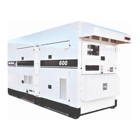
OPERATION MANUAL
WHISPERWATT™ SERIES
MODEL DCA600SSV4F3
60HZ GENERATOR
(VOLVO PENTA TWD1672GE DIESEL ENGINE)
INSTRUCTION MANUAL NO. C4844304614
Revision #2 (11/15/22)
To find the latest revision of this publication or
associated parts manual, visit our website at:
www.mqpower.com
THIS MANUAL MUST ACCOMPANY THE EQUIPMENT AT ALL TIMES.
Advertisement
Table of Contents
Troubleshooting

Related Manuals for MQ Power WHISPERWATT DCA600SSV4F3


Summary of Contents for MQ Power WHISPERWATT DCA600SSV4F3
- Page 1 OPERATION MANUAL WHISPERWATT™ SERIES MODEL DCA600SSV4F3 60HZ GENERATOR (VOLVO PENTA TWD1672GE DIESEL ENGINE) INSTRUCTION MANUAL NO. C4844304614 Revision #2 (11/15/22) To find the latest revision of this publication or associated parts manual, visit our website at: www.mqpower.com THIS MANUAL MUST ACCOMPANY THE EQUIPMENT AT ALL TIMES.
-
Page 2: Proposition 65 Warning
PROPOSITION 65 WARNING PAGE 2 — DCA600SSV4F3 60 HZ GENERATOR • OPERATION MANUAL — REV. #2 (11/15/22) -
Page 3: Table Of Contents
TABLE OF CONTENTS DCA600SSV4F3 NOTICE 60 Hz Generator Specifications are subject to change without notice. Proposition 65 Warning ........... 2 Table of Contents ............. 3 Safety Decals ............4 Safety Information ..........5–10 Specifications ............11 Dimensions ............12 Installation ............13–14 General Information .......... -
Page 4: Safety Decals
SAFETY DECALS SAFETY DECALS NOTICE Safety decals are attached to the generator as shown in For safety decal part numbers, refer to the associated Figure 1. Keep these safety decals clean at all times. When parts manual. the safety decals become worn or damaged, contact your nearest dealer or the Multiquip Parts Department. -
Page 5: Safety Information
SAFETY INFORMATION Do not operate or service the generator before reading the Potential hazards associated with the operation of this entire manual. Safety precautions should be followed at all generator will be referenced with hazard symbols which times when operating this generator. Failure to read and may appear throughout this manual in conjunction with understand the safety messages and operating instructions safety messages. - Page 6 „ NEVER use accessories or attachments that are not being used. The generator should be stored in a clean, dry location out of the reach of children and unauthorized recommended by MQ Power for this generator. Damage to the generator and/or injury to the user may result. personnel.
- Page 7 SAFETY INFORMATION ENGINE SAFETY „ Operation of the generator may create sparks that can start fi res around dry vegetation. A spark arrestor DANGER may be required. The operator should contact local fi re agencies for laws or regulations relating to fi re prevention „...
- Page 8 „ The trailer should be adjusted to a level position at all times when towing. „ Refer to the MQ Power trailer manual for additional safety information. „ Raise and lock the trailer wheel stand in the upright position when towing.
- Page 9 SAFETY INFORMATION ELECTRICAL SAFETY „ Make sure power cables are securely connected to the generator’s output receptacles. Incorrect connections DANGER may cause electrical shock and damage to the generator. „ NEVER touch the output terminals NOTICE during operation. Contact with the „...
- Page 10 SAFETY INFORMATION EMISSIONS INFORMATION „ If the battery liquid (dilute sulfuric acid) comes into contact with eyes, rinse eyes immediately with plenty NOTICE of water and contact the nearest doctor or hospital to seek medical attention. The diesel engine used in this equipment has been designed to reduce harmful levels of carbon monoxide CAUTION (CO), hydrocarbons (HC), and nitrogen oxides (NOx)
-
Page 11: Specifications
SPECIFICATIONS Table 1. Generator Specifications Model DCA600SSV4F3 Type Revolving field, self-ventilated, open protected type synchronous generator Armature Connection Star with neutral Phase Standby Output 528 kW (660 kVA) Prime Output 480 kW (600 kVA) 208, 220, 240, 416, 440, 480 3Ø... -
Page 12: Dimensions
DIMENSIONS TOP VIEW SIDE VIEW Table 3. Dimensions REAR VIEW (CONTROL PANEL VIEW) Reference Dimension in. (mm) Reference Letter Dimension in. (mm) Letter 26.97 in. (685 mm) 39.57 in. (1,005 mm) 27.36 in. (695 mm) 20.87 in. (530 mm) 40.94 in. (1,040 mm) 40.94 in. -
Page 13: Installation
GENERATOR GROUND LUG GROUND ROD GROUND CABLE REFERENCE NEC 250 Figure 3. Typical Generator Grounding Application NOTICE Trailer-mounted generators are the sole responsibility of MQ Power. DCA600SSV4F3 60 HZ GENERATOR • OPERATION MANUAL — REV. #2 (11/15/22) — PAGE 13... - Page 14 INSTALLATION OUTDOOR INSTALLATION MOUNTING Install the generator in an area that is free of debris, The generator must be mounted on a solid foundation bystanders, and overhead obstructions. Make sure the (such as concrete) and set firmly on the foundation to generator is on secure, level ground so that it cannot slide isolate vibration of the generator when it is running.
-
Page 15: General Information
„ Panel Light / Panel Light Switch for the generator. Refer to Table 2 for engine specifications. „ Hour Check Button In keeping with MQ Power’s policy of constantly improving „ 3-Pole, 1600-Amp Main Circuit Breaker its products, the specifications quoted herein are subject „... -
Page 16: General Paralleling Information (Option)
GENERAL PARALLELING INFORMATION (OPTION) The kVAR load sharing is achieved by increasing or NOTICE decreasing the field excitation to the system’s alternators. When the paralleling option is employed, the Basler As the field excitation of one generator set in a group is DGC-2020HD controller must be installed. - Page 17 GENERAL PARALLELING INFORMATION (OPTION) SEQUENCING ALARM SILENCE NOTICE Pre-Alarm Silence allows the user to suppress the toggling of the alarm screen when a new pre-alarm becomes active. Ethernet communication is required when the While a pre-alarm is active, press the Alarm Silence generators are configured for the Sequencing mode button to suppress the fault display.
- Page 18 GENERAL PARALLELING INFORMATION (OPTION) Preparation Ethernet Cable Connection 1. Make sure the generator is turned OFF and the engine 1. Connect a shielded CAT5E ethernet cable between is cool. port 1 on both generators as shown in Figure 4. 2. Disconnect any loads connected to the generator. 3.
-
Page 19: Major Components
MAJOR COMPONENTS Table 5. Major Components ITEM NO. DESCRIPTION Muffler Assembly Generator Assembly Battery Assembly Engine and Radiator Assembly Aftertreatment Control Module Assembly DEF Tank Assembly Control and Operation Panel Assembly Voltage Change-Over Board Assembly Main Circuit Breaker Assembly Emergency Stop Switch Assembly Fuel Tank Assembly Output Terminal Panel Assembly Figure 5. -
Page 20: Engine Control Unit (Ecu-845)
ENGINE CONTROL UNIT (ECU-845) Series 800 Controller Engine Started Shutdown Pre-Alarm Alarm Screen Program Option Acknowledge Change Exit Figure 6. Engine Control Unit (ECU-845) The definitions below describe the controls and functions When multiple engine faults occur, the lamp will of the engine control unit (ECU). -
Page 21: Gauge Unit Assembly
GAUGE UNIT ASSEMBLY RPMX10 °F OIL PRESS SPEED WATER TEMP ECU VOLTS Integrated Gauge Panel ½ ½ EATS System Malfunction °F °F Emission Related Malfunction Refill DEF FUEL EATS Error Fuel Figure 8. Gauge Unit Assembly The definitions below describe the readouts and functions of the gauge unit assembly (Figure 8). -
Page 22: Control And Operation Panel
CONTROL AND OPERATION PANEL °F RPMX10 OIL PRESS WATER TEMP SPEED ECU VOLTS Integrated Gauge Panel ½ ½ EATS System Malfunction °F °F Emission Related Malfunction Refill DEF EATS Error FUEL Fuel Series 800 Controller Engine Started Shutdown Pre-Alarm Alarm Screen Program Option... - Page 23 CONTROL AND OPERATION PANEL 12. Voltmeter Change-Over Switch — Allows the AC voltmeter to indicate phase-to-phase voltage between any two phases of the output terminals, or to be switched off. 13. Ammeter Change-Over Switch — Allows the AC ammeter to indicate the current flowing to the load connected to any phase of the output terminals, or to be switched off.
-
Page 24: Basler Digital Genset Controller (Option)
BASLER DIGITAL GENSET CONTROLLER (OPTION) Figure 10. Basler DGC-2020HD Controller NOTICE The Basler DGC-2020HD controller is an option. It replaces the standard ECU-845 controller when paralleling is to be employed. PAGE 24 — DCA600SSV4F3 60 HZ GENERATOR • OPERATION MANUAL — REV. #2 (11/15/22) - Page 25 BASLER DIGITAL GENSET CONTROLLER (OPTION) The definitions below describe the controls and functions 9. Off Pushbutton and Mode Indicator — Press this button to place the DGC-2020HD in Off mode.The of the digital genset controller (Figure 10). red Off Mode LED lights whenever the DGC-2020HD 1.
-
Page 26: Paralleling Panel (Option)
PARALLELING PANEL (OPTION) Figure 11. Paralleling Panel Components PAGE 26 — DCA600SSV4F3 60 HZ GENERATOR • OPERATION MANUAL — REV. #2 (11/15/22) - Page 27 PARALLELING PANEL (OPTION) The definitions below describe the controls and functions For units with manually operated breakers, the breaker of the paralleling panel (Figure 11). will need to be reset by toggling the handle down, then turning back to the ON position. On models with 1.
-
Page 28: Output Terminal Panel Familiarization
OUTPUT TERMINAL PANEL FAMILIARIZATION OUTPUT TERMINAL PANEL OUTPUT TERMINAL FAMILIARIZATION The output terminal panel (Figure 12) shown below is The output terminal panel (Figure 12) is provided with the provided for the connection of electrical loads. Lift up on following: the covers to gain access to receptacles and terminal lugs. - Page 29 OUTPUT TERMINAL PANEL FAMILIARIZATION 120-Volt AC GFCI Receptacles GFCI RECEPTACLES NOTICE It is recommended that the GFCI receptacles be tested LOAD when the generator is initially uncrated. The receptacles should then be tested daily at startup. There are two 120-volt, 20-amp GFCI (duplex NEMA 5-20R) receptacles provided on the output terminal panel.
-
Page 30: Load Application
LOAD APPLICATION SINGLE-PHASE LOAD THREE-PHASE LOAD Always be sure to check the nameplate on the generator When calculating the power requirements for 3-phase and equipment to ensure that the wattage, amperage, power, use the following equation: frequency, and voltage requirements are satisfactorily VOLTAGE ×... -
Page 31: Powerbalance
POWERBALANCE™ PowerBalance™ (Figure 16) is an optional load „ PowerBalance™ continuously monitors engine load by management solution that helps protect the engine generator sensing the engine exhaust temperature. from problems resulting from sustained low-load operations (defined as less than 30% of the generator full-load rating). POWERBALANCE™... -
Page 32: Generator Outputs
GENERATOR OUTPUTS GENERATOR OUTPUT VOLTAGES VOLTAGE REGULATOR A wide range of voltages (Table 8) is available for many To obtain some of the voltages listed in Table 8 will require different applications. a fine voltage adjustment using the voltage regulator (Figure 18) located on the control panel. -
Page 33: Gauge Reading
GAUGE READING HOW TO READ THE AC AMMETER AC Ammeter Gauge Reading AND AC VOLTMETER GAUGES Place the AC ammeter change-over switch (Figure 22) in the U position and observe the current reading (load drain) The AC ammeter and AC voltmeter gauges are controlled on the U terminal as indicated on the AC ammeter gauge by the AC ammeter and AC voltmeter change-over switches. -
Page 34: Output Terminal Panel Connections
OUTPUT TERMINAL PANEL CONNECTIONS UVWO TERMINAL OUTPUT VOLTAGES DECREASE INCREASE Various output voltages can be obtained using the UVWO output terminal lugs. The voltages at the terminals are dependent on the placement of the jumper plates (6) on the voltage change-over board (Figure 24) and the Figure 26. - Page 35 OUTPUT TERMINAL PANEL CONNECTIONS 3-Phase 480-Volt UVWO Terminal Output Voltages Single-Phase 480-Volt UVWO Terminal Output Voltages 1. Jumper the voltage change-over board for 480-volt operation as shown in Figure 29. This configuration 1. Make sure the voltage change-over board is jumpered uses 6 jumper plates in 3 different positions.
-
Page 36: Inspection/Setup
INSPECTION/SETUP ENGINE OIL CHECK 6. Fill with recommended type oil as listed in Table 10. Maximum oil capacity is 12.7 gallons (48 liters). 1. To check the engine oil level, place the generator on secure, level ground with the engine stopped. 2. - Page 37 INSPECTION/SETUP FUEL CHECK Refueling Procedure DANGER NOTICE ALWAYS fill the fuel tank with clean, fresh #2 diesel fuel. Fuel spillage on a hot engine can cause a fire or explosion. If fuel spillage occurs, NEVER fill the fuel tanks beyond their capacities. wipe up the spilled fuel completely to WARNING prevent fire hazards.
- Page 38 INSPECTION/SETUP 2. Fill the trailer fuel tank first. The trailer fuel tank is 4. Once the trailer tank is full, the secondary, internal the primary fuel tank and has a larger fuel capacity. The tank can be filled (Figure 40). Notice how the level fuel in the trailer will be filtered and sent to the engine.
- Page 39 INSPECTION/SETUP DEF REFUELING COOLANT Volvo recommends pre-diluted Volvo Penta Coolant VCS NOTICE (yellow). See the Volvo engine owner’s manual for further ONLY fill the DEF tank with diesel exhaust fluid. Any details. other type of fluid may cause severe engine damage. WARNING Diesel exhaust fluid (DEF) is an aqueous solution When adding coolant/antifreeze mix to the...
- Page 40 INSPECTION/SETUP Operation In Freezing Weather AIR CLEANER When operating in freezing weather, be certain the proper Periodic cleaning/replacement of the air cleaner is amount of antifreeze (Table 12) has been added. necessary. Inspect the air cleaner in accordance with the maintenance section of this manual.
- Page 41 INSPECTION/SETUP BATTERY POSITIVE This unit is of negative ground. DO NOT connect in reverse. ALWAYS maintain battery fluid level between the specified marks. Battery life will be shortened if the fluid level is not properly maintained. Add only distilled water when replenishment is necessary.
- Page 42 INSPECTION/SETUP Battery Switch WIRING Located in the engine compartment, the Battery switch Inspect the entire generator for bad or worn electrical wiring (Figure 48) connects and disconnects the battery. Place or connections. If any wiring or connections are exposed the switch in the ON position prior to starting the generator. (insulation missing) replace the wiring immediately.
-
Page 43: Generator Startup Procedure (Manual)
GENERATOR STARTUP PROCEDURE (MANUAL) BEFORE STARTING CAUTION The engine’s exhaust contains harmful emissions. ALWAYS have adequate ventilation when operating. Direct exhaust away from nearby personnel. WARNING NEVER manually start the engine with the main or auxiliary circuit breakers in the ON (closed) position. Figure 51. - Page 44 GENERATOR STARTUP PROCEDURE (MANUAL) 7. Close all engine enclosure doors (Figure 53). 5. The frequency meter (Figure 58) displays the 60-cycle output frequency in hertz. 60 Hz CORRECT INCORRECT Figure 53. Engine Enclosure Doors Figure 58. Frequency Meter STARTING (MANUAL) 6.
- Page 45 GENERATOR STARTUP PROCEDURE (MANUAL) 9. The engine oil pressure gauge (Figure 62) indicates 13. Verify that the Main Circuit Breaker ON lamp (Figure 66) is lit (ON). the oil pressure of the engine. Under normal operating conditions this gauge should indicate approximately 44–94 psi.
-
Page 46: Generator Startup Procedure (Auto Mode)
GENERATOR STARTUP PROCEDURE (AUTO MODE) STARTING (AUTO MODE) When starting the generator in AUTO mode, use the manual startup procedure except where noted below. NOTICE 1. Perform steps 1–4 of the Before Starting section of Before connecting this generator to any building’s the Generator Startup Procedure (Manual). -
Page 47: Generator Shutdown Procedures
GENERATOR SHUTDOWN PROCEDURES NORMAL SHUTDOWN PROCEDURE 6. Place the Auto Start/Stop switch (Figure 76) in the OFF/RESET position. WARNING NEVER stop the engine suddenly except in an emergency. MANUAL AUTO OFF/RESET 1. Place the GFCI circuit breakers in the OFF position Figure 76. - Page 48 GENERATOR SHUTDOWN PROCEDURES EMERGENCY SHUTDOWN PROCEDURE NOTICE The Emergency Stop switch should only be used to stop the engine in case of an emergency or to lock out operation during service. The Emergency Stop switch should NEVER be used for routine stopping of the engine.
-
Page 49: Maintenance
MAINTENANCE Every 500 Every 1,000 Every 2,000 Table 13. Inspection/Maintenance Daily Hours Hours Hours Check Engine Oil and Coolant Levels Check Fuel Filter / Water Bowl Check Battery Fluid Level Check Air Cleaner Check for Leaks Visual Walk-Around Inspection Check Coolant Antifreeze Mixture Clean Air Cleaner Element Drain Bottom of Fuel Tank Drain Bottom of Fuel Pre-Filter... - Page 50 MAINTENANCE GENERAL INSPECTION Primary And Secondary Air Cleaner Elements Prior to each use, the generator should be cleaned and Every 250 hours: Remove the air cleaner elements and inspected for deficiencies. Check for loose, missing, or clean them with a light spray of compressed air. damaged nuts, bolts, or other fasteners.
- Page 51 MAINTENANCE Air Cleaner Restriction Indicator Draining Fuel Filter Condensate The air cleaner is equipped with a restriction indicator 1. Place an appropriate container underneath the fuel (Figure 80). As the air cleaner element becomes clogged, filter to collect the condensate (water) and fuel as it air intake restriction increases and the indicator signal drains.
- Page 52 MAINTENANCE 3. Clean the filter mating surface on the filter bracket 6. Lubricate the seal with diesel fuel. Screw the filter (Figure 82). onto the filter bracket by hand until the rubber seal just touches the mating surface. Then tighten another 4.
- Page 53 MAINTENANCE CLEANING INSIDE THE FUEL TANK DRAINING THE ENGINE OIL If necessary, drain the fuel inside the fuel tank completely. 1. Run the engine until the engine coolant reaches a Using a spray washer (Figure 85), wash out any deposits temperature of 140°F (60°C).
- Page 54 MAINTENANCE ENGINE OIL FILTER REPLACEMENT 6. Fill the engine crankcase with high-quality detergent oil classified “For Service CI-4.” Fill to the upper limit 1. Clean the area around the oil filter bracket (Figure 87). of the dipstick. DO NOT overfill. Refer to Table 2 for engine oil capacity.
- Page 55 MAINTENANCE FLUSHING OUT THE RADIATOR 2. Open the cabinet door and remove the coolant drain bolt and O-ring (Figure 89), then allow the coolant to AND REPLACING COOLANT drain into a suitable container. WARNING Allow the engine to cool before flushing out the radiator.
- Page 56 MAINTENANCE Cleaning The Radiator The radiator should be cleaned with water and a mild detergent when excessive amounts of dirt and debris have accumulated on the cooling fins or tubes. Use a soft brush. Be careful to not damage the radiator fins. NOTICE DO NOT use a high-pressure power washer (Figure 90) to clean the radiator.
- Page 57 MAINTENANCE 3. Verify that the status LED on the corresponding GFCI 7. Repeat the above procedure for all other GFCI receptacle (Figure 93) is ON (GREEN). receptacles. GENERATOR STORAGE For long-term storage of the generator the following is GREEN recommended: STATUS LED (ON) „...
- Page 58 MAINTENANCE OPTIONAL ENGINE BLOCK HEATER AND When using the generator in hot climates there is no reason to apply power to the engine block heater. However, if the INTERNAL BATTERY CHARGER generator will be used in cold climates it is always a good 120 VAC INPUT RECEPTACLES idea to apply power to the heater at all times.
- Page 59 MAINTENANCE EMISSION CONTROL PREVENTIVE MAINTENANCE PROGRAMS The emission control system employed with this diesel Most challenging to a rental organization is the fact that a engine consists of a diesel oxidation catalyst (DOC) customer’s power assumptions may not meet the minimum and a selective catalytic reduction (SCR) catalyst load requirements of the power equipment selected.
- Page 60 MAINTENANCE SELECTIVE CATALYTIC REDUCTION (SCR) Diesel engines can be run with a lean burn air-to-fuel ratio, Series 800 Controller Engine Started to ensure the full combustion of soot and to prevent the DEF STAT exhaust of unburnt fuel. The excess of air necessarily leads Shutdown to generation of nitrogen oxides (NO ), which are harmful...
- Page 61 MAINTENANCE INDUCEMENT When the system senses improper usage, such as no supply of DEF, use of poor quality DEF, problems with DEF dosing, or disconnection of sensors, a warning will be issued before the situation becomes critical. If the warnings are ignored and the unit enters intermittent operation, the emergency shutdown will activate.
- Page 62 MAINTENANCE PROTECTION DEVICES Place the Auto Start/Stop switch in the OFF/RESET position. In addition, place all circuit breakers in the OFF Automatic Shutdown System position. Before troubleshooting, allow sufficient time for adequate cooling. Before attempting to restart the This unit is equipped with engine protection devices that generator, perform an overall inspection of the generator automatically shut down the engine if any of the faults and correct the problem that caused the shutdown.
-
Page 63: Troubleshooting (Diagnostics)
TROUBLESHOOTING (DIAGNOSTICS) FAULT DIAGNOSTICS 5. Push the Program/Exit button on the ECU controller and select Fault Diagnostics mode. This mode The engine controller of this generator diagnoses problems enables fault diagnostics as follows: (faults/errors) that arise from the engine control system and „... -
Page 64: Troubleshooting (Generator)
TROUBLESHOOTING (GENERATOR) Practically all breakdowns can be prevented by proper handling and maintenance inspections, but in the event of a breakdown, use Table 17 below for diagnosis of the generator. If the problem cannot be remedied, consult our company’s business office or service plant. Table 17. -
Page 65: Troubleshooting (Engine)
TROUBLESHOOTING (ENGINE) Troubleshooting (Diesel Engine) Symptom Possible Problem Solution No fuel? Replenish fuel. Air in the fuel system? Bleed system. Water in the fuel system? Remove water from fuel tank. Fuel pipe clogged? Clean fuel pipe. Fuel fi lter clogged? Clean or change fuel fi lter. - Page 66 TROUBLESHOOTING (ENGINE) Troubleshooting (Diesel Engine) continued Symptom Possible Problem Solution Fuel fi lter clogged or dirty? Clean or change. Air cleaner clogged? Clean or change. Fuel leak due to loose injection pipe retaining Tighten nut. nut? Injection pump malfunctioning? Repair or replace. Engine revolution is not smooth.
-
Page 67: Generator Wiring Diagram (C4814005103A)
GENERATOR WIRING DIAGRAM (C4814005103A) DCA600SSV4F3 60 HZ GENERATOR • OPERATION MANUAL — REV. #2 (11/15/22) — PAGE 67... -
Page 68: Engine Wiring Diagram (C4814106813)
ENGINE WIRING DIAGRAM (C4814106813) PAGE 68 — DCA600SSV4F3 60 HZ GENERATOR • OPERATION MANUAL — REV. #2 (11/15/22) -
Page 69: Mcb Sequence Diagram (C4814209104)
MCB SEQUENCE DIAGRAM (C4814209104) MCB SEQUENCE DIAGRAM NO. C4814209104 DCA600SSV4F3 60 HZ GENERATOR • OPERATION MANUAL — REV. #2 (11/15/22) — PAGE 69... -
Page 70: Engine Block Heater Wiring Diagram (Option)
ENGINE BLOCK HEATER WIRING DIAGRAM (OPTION) BLACK 14 AWG. LINE (L)120VAC INPUT WHITE 14 AWG. NEUTRAL (N) GREEN 14 AWG. GROUND (G) ENGINE BLOCK HEATER TEMP. BLACK 14 AWG. SWITCH LINE (L)120VAC INPUT HEATING 120 VAC WHITE 14 AWG. ELEMENT NEUTRAL (N) GREEN 14 AWG. -
Page 71: Battery Charger Wiring Diagram (Option)
BATTERY CHARGER WIRING DIAGRAM (OPTION) BLACK 14 AWG. LINE (L)120VAC INPUT WHITE 14 AWG. NEUTRAL (N) GREEN 14 AWG. GROUND (G) TO CHASSIS GROUND GREEN 16 AWG. TO STARTER “B” TERMINAL RED 16 AWG. 120 VAC INPUT, INSERT EXTERNAL POWER CORD HERE. NOTES: NEMA 5-15, 15A, 120 VAC, P/N EE6176 (HBL5278C/HUBBLE RECEPTACLE). - Page 72 © COPYRIGHT 2022, MULTIQUIP INC. Multiquip Inc , the MQ logo and the MQ Power logo are registered trademarks of Multiquip Inc. and may not be used, reproduced, or altered without written permission. All other trademarks are the property of their respective owners and used with permission.