Table of Contents
Advertisement
Quick Links
ProPane TenT evenT
Forced air HeaTer
TENT
Event
125
oWner'S ManUaL
by
ModeLS TB116, TB117 and TB118
125,000 BTU/Hr
IMPORTANT: Read and understand this manual before
assembling, starting or servicing heater. Improper use
of heater can cause serious injury. Keep this manual for
future reference.
GENERAL HAZARD WARNING:
Failure to comply with the precautions and instructions
provided with this heater, can result in death, serious
bodily injury and property loss or damage from hazards
of fire, explosion, burn, asphyxiation, carbon monoxide
poisoning and/or electrical shock.
Only persons who can understand and follow the instruc-
tions should use or service this heater.
If you need assistance or heater information such as an in-
structions manual, labels, etc. contact the manufacturer.
Save this manual for future reference.
For more information, visit www.desatech.com
Advertisement
Table of Contents

Related Manuals for Master TentEvent 125


Summary of Contents for Master TentEvent 125
- Page 1 ProPane TenT evenT Forced air HeaTer TENT Event oWner’S ManUaL ModeLS TB116, TB117 and TB118 125,000 BTU/Hr IMPORTANT: Read and understand this manual before assembling, starting or servicing heater. Improper use of heater can cause serious injury. Keep this manual for future reference.
-
Page 2: Table Of Contents
WARNING: If the information in this manual is not followed exactly, a fire or explosion may result causing property damage, personal injury or loss of life. — Do not store or use gasoline or other flammable va- pors and liquids in the vicinity of this or any other appliance. -
Page 3: Safety
SaFeTy General WARNING: This product ANSI/NFPA 102 contains and/or generates Standard for Grandstands, Folding and chemicals known to the State telescopic Seating, Tents and Mem- of California to cause cancer or brane Structures ANSI/NFPA 58 birth defects or other reproduc- Standard for Storage and Handling of tive harm. - Page 4 SaFeTy Continued Note: Fan will continue running if fuel supply CAUTION: Any safety screen is exhausted or thermal switch opens. or guard removed for servicing DANGER: Carbon monoxide an appliance must be replaced poisoning may lead to death! prior to operating the heater. Carbon Monoxide Poisoning: Early signs 1.
-
Page 5: Ventilation
SaFeTy Continued 11. Minimum heater clearances from com- 29. The heater must be installed so that the bust ble materials: Outlet: 8 ft. (2.40 m), location of the heater does not obstruct or Sides: 1 ft. (30 cm), Top: 3 ft. (0.91 m), interfere with normal or emergency exits Rear: 1 ft. -
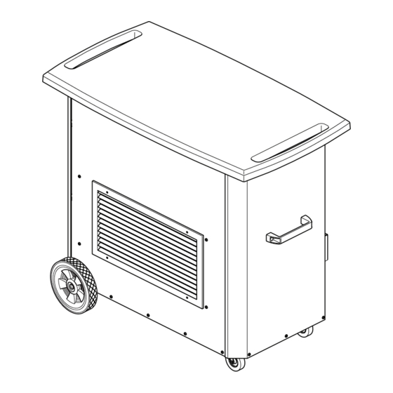
Page 6: Product Identification
ProdUcT idenTiFicaTion Hand Holds for Pushing Thermostat Knob ON/OFF Switches Lifting Handle Hose and Regulator Assembly Receptacle Power Cord Gas Inlet Figure 1 - Tent Heater ProPane SUPPLy Propane/LP gas and propane tank(s) are to 1. The amount of propane gas in tank(s) be furnished by the user. -
Page 7: Electrical Supply
eLecTricaL SUPPLy This heater requires an electrical supply to OPERATION WITH PORTAbLE be furnished by the user. The electrical outlet GENERATOR should have the following ratings: 120 volts (+/- 10%), 60 Hertz, 15 Amps WARNING: before operating Ground Fault Interrupter (GFI) heater or any appliance from a The heater uses the ground circuit to prove the portable generator, verify that... -
Page 8: Theory Of Operation
THeory oF oPeraTion The Fuel System: The hose/regulator assembly attaches to the propane gas supply. The propane gas moves through the automatic control valve and out the injector. The Air System: The motor turns the fan. The fan pulls air into and around the combustion chamber. -
Page 9: Assembly
aSSeMBLy ASSEMbLY ITEMS Before assembling heater, make sure you have the items listed below. • Phillips head screwdriver • Wrench • Hardware packet Handles (2), 3/4" Screws (4), 1/4-20 Nuts (4), 1/4 Flat washers (4), 1/4 Lock washers (4) Casters (2), 3/8" Nut (2), 3/8 Lock washers (2), 3/8 Flat Washers (4) Wheels (2), Push Caps (2) Brackets (4), 1/2"... - Page 10 aSSeMBLy Continued Wheels and Axle 1. Locate wheels, spacers and axle in Heater packaging. Remove 2 push caps from Front hardware packet. 2. Stand axle upright placing one end on the floor. Gently tap one push cap onto end Spacer of axle.
-
Page 11: Installation
inSTaLLaTion 2. Connect fuel gas connector fitting on WARNING: Review and un- hose/regulator assembly to propane derstand the warnings in the tank(s) (see Figure 7). Turn counterclock- wise into threads on tank valve. Tighten Safety section, page 2. They are firmly using wrench. -
Page 12: Operation
oPeraTion CONTINUOUS FAN WITH HEAT WARNING: Review and un- 1. Press Switch 1 to ON. derstand the warnings in the 2. Press Switch 2 to ON. Safety section, page 2. They are 3. Adjust thermostat knob to desired needed to safely operate this comfort level. -
Page 13: Storage
STorage 2. Place plastic cover caps over brass fittings CAUTION: Disconnect heater on inlet connector and hose/regulator as- sembly. from propane supply tank(s). 3. Store in dry, clean, and safe place. 1. Store propane tank(s) in safe manner. See 4. When taking heater out of storage, always Chapter 5 of Standard for Storage and check inside of heater. - Page 14 Service Continued TOP AND SIDE PANEL REMOVAL 2. Remove 2 screws securing side panel at top edge. Remove 3 screws at lower 1. Remove 8 screws securing top brackets outside edge (see Figure 10). Push down to body panels. Remove top and set aside and lift out side panel.
- Page 15 Service Continued Baffle Top Blower Mounting Panel Terminal Blocks Blower/Motor Outlet Louver Figure 11 - Removing Blower/Motor Assembly while inserting burner locator pin into hole bURNER, IGNITOR AND GAS in chamber end panel. Replace screen ORIFICE and back panel. Back Panel WARNING: Make sure heater is disconnected from propane and electrical supply.
- Page 16 Service Continued Replacing Ignitor REPLACING GAS VALVE 1. To loosen back panel and gain access 1. Remove top and side panel (see Top and to ignitor, follow step 1 under Replacing Side Panel Removal, page 14). Burner, page 15. Due to lack of working 2.
-
Page 17: Specifications
Service Continued Switches Thermostat Terminal Boards Thermal Limit Switch Receptacle Pressure Switch Pressure Solenoid Valve Vacuum Pressure Injector Gas Line Burner Figure 15 - Tent Heater Parts SPeciFicaTionS • Output Rating - 125,000 Btu/Hr (131,882 kJ/Hr) • Fuel Consumption - 1.4 Gal/Hr (5.2 Liters/Hr), 5.8 lb/Hr (2.6 kg/Hr) •... -
Page 18: Troubleshooting
TroUBLeSHooTing WARNING: Never service heater while it is plugged in, connected to propane supply, operating, or hot. Severe burns and electrical shock can occur. ObSERVED FAULT POSSIbLE CAUSE REMEDY Fan does not turn when 1. No electrical power to heater 1. -
Page 19: Technical Service
TroUBLeSHooTing Continued ObSERVED FAULT POSSIbLE CAUSE REMEDY Heater shuts down while 1. Propane supply may be 1. A) Refill tank running inadequate B) Provide additional and/or larger tanks. See Propane Supply, page 6 2. High surrounding air tem- 2. This can happen when running perature causing thermal heater in temperatures above limit device to shut down... -
Page 20: Wiring Diagram
Wiring diagraM Switch 2 Switch 1 Continuous Cycle Orange Rojo Rojo Naranja Rouge Rouge (encendedor Black de chispa Negro directa) White Noir Blanco/Blanc Motor White Moteur Blanco/Blanc Green White Verde Switch Vert Blanco Blanc Black Negro Noir Black Negro Noir Thermostat Black Green... - Page 21 Wiring diagraM Continued Ignitor Encendedor S1 = Switch 1 Allumeur Orange S2 = Switch 2 Solenoid Valve VAC = VAC Switch Naranja T/S = Thermal Switch Blue/Azul/Bleu T = Thermostat Blue Azul Bleu Blue/Azul/Bleu Black Negro/Noir White Black Blanco Negro Noir Blanc (1) Interruptor 1 ciclo automático/...
-
Page 22: Parts
ParTS CAbINET MODELS Tb116, Tb117 AND Tb118 www.desatech.com 120193-01C... - Page 23 ParTS CAbINET This list contains replaceable parts used in your heater. When ordering parts, follow the instructions listed under Replacement Parts on page 26 of this manual. NO. PART NO. DESCRIPTION 119551-01 Cabinet Top, White • 119551-02 Cabinet Top, Black •...
- Page 24 ParTS MODELS Tb116, Tb117 AND Tb118 www.desatech.com 120193-01C...
- Page 25 ParTS MODELS Tb116, Tb117 AND Tb118 This list contains replaceable parts used in your heater. When ordering parts, follow the instructions listed under Replacement Parts on page 26 of this manual. NO. PART NO. DESCRIPTION M51605-05 D.S.I. Control • • •...
-
Page 26: Replacement Parts
rePLaceMenT ParTS acceSSory Purchase accessories and parts from your WARNING: Use only original nearest dealer or service center. If your dealer replacement parts. This heater or service center can not supply an accessory or part, call DESA Heating Products’ Parts must use design-specific parts. - Page 27 noTeS _____________________________________________________ ______________________________________________________ ______________________________________________________ ______________________________________________________ ______________________________________________________ ______________________________________________________ ______________________________________________________ ______________________________________________________ ______________________________________________________ ______________________________________________________ ______________________________________________________ ______________________________________________________ ______________________________________________________ _____________________________________________________ ______________________________________________________ ______________________________________________________ ______________________________________________________ ______________________________________________________ ______________________________________________________ ______________________________________________________ ______________________________________________________ ______________________________________________________ ______________________________________________________ ______________________________________________________ ______________________________________________________ ______________________________________________________ _____________________________________________________ ______________________________________________________ ______________________________________________________ ______________________________________________________ ______________________________________________________ ______________________________________________________ ______________________________________________________ ______________________________________________________ ______________________________________________________ 120193-01C www.desatech.com...
-
Page 28: Warranty
WarranTy keeP THiS WarranTy Model.._____________________________________ Serial.No...__________________________________ Date.of.Purchase..____________________________ LiMiTed WarranTieS For neW and FacTory recondiTioned ProdUcTS New Products:.DESA.Heating,.LLC.warrants.this.heater.and.any.parts.thereof,.to.be.free.of.defects. in materials and workmanship for one (1) year from the date of first purchase, when operated and maintained.in.accordance.with.the.manufacturer's.instructions..These.warranties.are.extended.only.to. the.original.retail.purchaser,.when.proof.of.purchase.is.provided. Factory Reconditioned Heaters:.DESA.Heating,.LLC.warrants.this.factory.reconditioned.heater.and. any.parts.thereof,.to.be.free.of.defects.in.materials.and.workmanship.for.thirty.(30).days.from.the.date.of. first purchase, when operated and maintained in accordance with the manufacturer's instructions.