Table of Contents
Advertisement
Quick Links
A l l t e s t I n s t r u me n t s , I n c .
5 0 0 C e n t r a l A v e .
F a r mi n g d a l e , N J 0 7 7 2 7
P : ( 7 3 2 ) 9 1 9 - 3 3 3 9
F : ( 7 3 2 ) 9 1 9 - 3 3 3 2
a l l t e s t . n e t
s s a l e s @ a l l t e s t . n e t
T h e t e s t & me a s u r e me n t
e q u i p me n t y o u n e e d a t
t h e p r i c e y o u w a n t .
A l l t e s t c a r r i e s t h e w o r l d ' s l a r g e s t s e l e c t i o n o f
u s e d / r e f u r b i s h e d b e n c h t o p t e s t & me a s u r e me n t
e q u i p me n t a t 5 0 % t h e p r i c e o f n e w .
O O u r e q u i p me n t i s g u a r a n t e e d w o r k i n g , w a r r a n t i e d , a n d
a v a i l a b l e w i t h c e r t i f i e d c a l i b r a t i o n f r o m o u r i n - h o u s e s t a f f
o f t e c h n i c i a n s a n d e n g i n e e r s .
• 1 0 + f u l l t i me t e c h n i c i a n s w i t h o v e r 1 5 0 y e a r s o f
s p e c i a l i z a t i o n
• 9 0 d a y w a r r a n t y & 5 d a y r i g h t o f r e t u r n o n a l l
e q u i p me n t
• • 1 - 3 y e a r w a r r a n t i e s f o r n e w a n d
p r e mi u m- r e f u r b i s h e d e q u i p me n t
• E v e r y u n i t t e s t e d t o O E M s p e c i f i c a t i o n s
• S a t i s f a c t i o n g u a r a n t e e d
Y o u h a v e p l a n s , w e w i l l h e l p y o u a c h i e v e t h e m.
A n y p r o j e c t . A n y b u d g e t .
t
G e t a q u o t e t o d a y !
C C a l l ( 7 3 2 ) 9 1 9 - 3 3 3 9 o r e ma i l s a l e s @a l l t e s t . n e t .
Advertisement
Table of Contents

Related Manuals for Agilent Technologies 1155A


Summary of Contents for Agilent Technologies 1155A
- Page 1 T h e t e s t & me a s u r e me n t e q u i p me n t y o u n e e d a t t h e p r i c e y o u w a n t . A l l t e s t I n s t r u me n t s , I n c .
- Page 2 User’s Guide Publication number 01155-92003 July 2003 For Safety and Regulatory information, and publishing information, see the pages at the back of this book. © Copyright Agilent Technologies 1998-2003 All Rights Reserved. 1155A 2-Channel, Low-Mass Active Oscilloscope Probe...
-
Page 3: Table Of Contents
Operating the probe 8 How to replace the probe cable and tip 10 Cleaning the probe 11 Returning the probe to Agilent Technologies for service 11 Adjusting the 1155A 12 Setting up test system 13 Determine probe pass/fail criteria 15... -
Page 4: Inspect The Probe
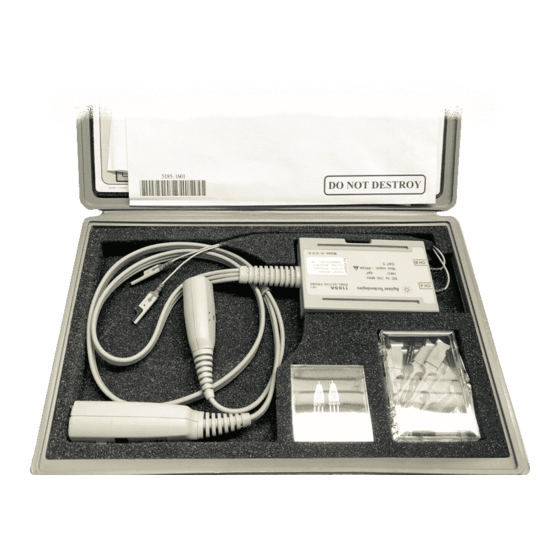
Office. • If the shipping container is damaged, or the cushioning materials show signs of stress, notify the carrier as well as your Agilent Technologies Sales Office. Keep the shipping materials for the carrier’s inspection. The Agilent Technologies office will arrange for repair or replacement at Agilent... - Page 5 Inspect the probe 1155A 2-Channel, Low-Mass Active Oscilloscope Probe The 1155A 2-Channel, Low-Mass Active Oscilloscope Probe is a 10:1 probe with a 750 MHz bandwidth. The FET amplifier allows a high-input resistance (1 MΩ, <2 pF) and low input capacitance which minimizes the loading of the circuit under test.
- Page 6 1155A 2-Channel, Low-Mass Active Oscilloscope Probe Inspect the probe Item Description Wedge Probe Adapter (2613A) You can order additional quantities of these parts. See the ordering information in this manual. Replacement parts Item Quantity Part number Probe tip and cable...
-
Page 7: Probe Specifications
1155A 2-Channel, Low-Mass Active Oscilloscope Probe Probe specifications Probe specifications ≤470 ps Rise time: Attenuation: 10:1 ±3% Input Resistance: 1 MΩ ±2% Above 35 °C, bandwidth and rise time degrade approximately 1/2% / °C. Bandwidth figure calculated from BW = 0.35 / t (rise time). -
Page 8: General Characteristics
1155A 2-Channel, Low-Mass Active Oscilloscope Probe General characteristics General characteristics General Characteristics of the 1155A Probe Environmental Operating Non-operating Conditions Temperature 0 °C to +55 °C -40 °C to +70 °C Humidity Up to 95% relative humidity Up to 90% relative humidity at +65 °C. -
Page 9: Operating The Probe
1155A 2-Channel, Low-Mass Active Oscilloscope Probe Operating the probe Operating the probe The following information will help you get the most out of your measurement when operating the probe. Operating Voltage Derating Typical Input Impedance vs. Frequency... - Page 10 1155A 2-Channel, Low-Mass Active Oscilloscope Probe Operating the probe Typical Rise Time vs. Input Voltage System bandwidths The approximate system bandwidths are shown here when using the 1155A Active Probe with these Infiniium Oscilloscopes: When Using this Scope: System Bandwidth is: 500 MHz Infiniium Oscilloscope Approximately 500 MHz 1.5 GHz Infiniium Oscilloscope...
-
Page 11: How To Replace The Probe Cable And Tip
1155A 2-Channel, Low-Mass Active Oscilloscope Probe How to replace the probe cable and tip How to replace the probe cable and tip To replace the main cable Due to the difficulty in soldering the main cable to the printed circuit assembly,... -
Page 12: Cleaning The Probe
Do not use petroleum based solvents to clean the probe. Returning the probe to Agilent Technologies for service Before shipping the instrument to Agilent Technologies, contact your nearest Agilent Technologies Sales Office for additional details. Write the following information on a tag and attach it to the instrument. -
Page 13: Adjusting The 1155A
Adjusting the 1155A Adjusting the 1155A There is no defined adjustment interval for the 1155A active probe. The adjustments are done at Agilent Technologies and do not require periodic maintenance. You should only make adjustments when replacing the probe tip. -
Page 14: Setting Up Test System
1155A 2-Channel, Low-Mass Active Oscilloscope Probe Setting up test system Setting up test system To determine test system rise time, connect the equipment as shown below. Then go to the next step to make the control settings on the oscilloscope. - Page 15 Mean rise time of channel 1: __________ Mean rise time of channel 2: __________ This information will be required for calculating the 1155A rise time. You should expect to see that the rise times for channel 1 and channel 2 are...
-
Page 16: Determine Probe Pass/Fail Criteria
Determine probe pass/fail criteria Determine probe pass/fail criteria The 1155A Probe is specified to have a rise time of ≤ 470 ps. The combined rise time of the total system (8131A, 1155A, and 54845A) is approximately 539 ps worst case. -
Page 17: Set Up For Probe Adjustment
Set up for probe adjustment Attach the probe to the setup you made earlier setting up test system as indicated below. Equipment Setup with 1155A Active Probe Attached Remove the 50 Ω cables from channel 1 and channel 2 of the oscilloscope. -
Page 18: Adjusting The Probe
1155A 2-Channel, Low-Mass Active Oscilloscope Probe Adjusting the probe Connect BNC to probe tip adapter to the terminations and connect the 1155A probes. Remove the 4 screws of the probe housing using the T10 torx driver. Adjusting the probe Change the oscilloscope settings as follows: •... - Page 19 1155A 2-Channel, Low-Mass Active Oscilloscope Probe Adjusting the probe Change the scope to 1 ns/div. Adjust the oscilloscope’s position to place the leading edge two major divisions from the left-hand side of the oscilloscope. Drag and drop the rise time icon to the channel 1 display. Then pull the rise time icon to the channel 2 display.
- Page 20 1155A 2-Channel, Low-Mass Active Oscilloscope Probe Adjusting the probe Adjust DAMP for about 6% overshoot. RA, RB, and DAMP are mutually dependent. DAMP 01145w05 Repeat steps 10 through 12 to achieve the best pulse. Temporarily place the cover on top of the probe body, then measure the pulse rise time.
-
Page 21: Calibration Testing Procedures
When you return the 1155A probe to Agilent for calibration, a new certificate is provided which verifies that the probe performed within specified limits and against equipment which is traceable to the National Institute of Standards and Technology. -
Page 22: Verifying Probe Input Resistance
1155A 2-Channel, Low-Mass Active Oscilloscope Probe Verifying probe input resistance Verifying probe input resistance Specification: 1.0 MΩ ±2% Equipment Required Equipment Critical Specification Recommended Model/Part Digital Multimeter Resistance ±1% 34401A (DMM) Connect the DMM probes between the probe tip (ChA) and the ground at the tip of the probe. - Page 23 1155A 2-Channel, Low-Mass Active Oscilloscope Probe Verifying probe rise time To determine test system rise time, connect the equipment as shown below. Then go to the next step to make the control settings on the oscilloscope. Setting Up Test Equipment...
- Page 24 Mean rise time of channel 1: __________ Mean rise time of channel 2: __________ This information will be required for calculating the 1155A rise time. You should expect to see that the rise times for channel 1 and channel 2 are...
-
Page 25: Set Up For Probe Rise Time Verification
Set up for probe rise time verification Attach the probe to the setup you made earlier as indicated below. Equipment Setup with 1155A Active Probe Attached Adjust the oscilloscope position for leading edge of the waveform to be 2 major divisions from the left-hand side of the screen. - Page 26 1155A 2-Channel, Low-Mass Active Oscilloscope Probe Set up for probe rise time verification Record the total system rise time for channels 1 and 2. Mean rise time of channel A : __________ total Mean rise time of channel B : __________...
- Page 27 1155A 2-Channel, Low-Mass Active Oscilloscope Probe Set up for probe rise time verification Calibration Test Record 1155A Active Probe Agilent Technologies Serial Tested No._________________________________ by__________________________________ Recommended Test Interval - 1 Year/2000 hours Work Order Recommended next testing_______________ No._________________________________ Date________________________________ Temperature__________________________...
- Page 28 This product was tested in a typical configuration with Agilent Technologies test systems. Colorado Springs, 11/13/98 Ken Wyatt / Product Regulations Manager European Contact: Your local Agilent Technologies Sales and Service Office or Agilent Technologies GmbH, Department ZQ / Standards Europe, Herrenberger Strasse 130, D-71034 Boeblingen, Germany (FAX +49-7031-14-3143)
- Page 29 Product Regulations Safety IEC 1010-1: 1990+A1 / EN 61010-1: 1993 UL 3111 CSA-C22.2 No.1010.1:1993 This Product meets the requirements of the European Communities (EC) EMC Directive 89/336/EEC. Emissions EN55011/CISPR 11 (ISM, Group 1, Class A equipment), IEC 555-2 and IEC 555-3 Code Immunity EN50082-1...
- Page 30 • Whenever it is likely that the ground protection is impaired, you must make the instrument inoperative and secure it against any unintended opera- tion. Agilent Technologies P.O. Box 2197 1900 Garden of the Gods Road Colorado Springs, CO 80901...
- Page 31 A WARNING notice contained herein, includ- denotes a hazard. It calls ing but not limited to the © Agilent Technologies, Inc. attention to an operating implied warranties of 1998 - 2003 procedure, practice, or merchantability and fit-...
- Page 33 Agilent Technologies Printed in the Malaysia Manual Part Number 01155-92003 *01155-92003*...